Frama Matrix F Series Instruction sheet

IP Configuration Manual

Safety precautions and warnings
Thank you for deciding to use a Frama Franking System.
The information in this guide is intended to support you during the configuration of the franking system to connect
via TCP / IP to FramaOnline2.
Your franking system meets currently valid safety regulations. Inappropriate use, however, can lead to personal injury
or damage to property. With this in mind, please read this guide first before you put the unit into service. By doing so,
you will protect yourself and avoid damaging the unit. Store this guide carefully and pass it along to any subsequent
owner.
Symbols used
This configuration guide uses the following symbols:
Danger!
This symbol points to dangers and safety risks when handling, operating or servicing your franking
system which could result in personal injury.
Note!
This symbol points to valuable guidelines and instructions for handling your franking system which
can eliminate the risk of damage to the franking system, the mail items or the
immediate environment.
Tip!
Interesting notes and tips for efficient handling.

Table of Contents
1INTRODUCTION ...............................................................................................................................4
2OVERVIEW TCP/IP CONNECTION FRAMA MATRIX F SERIES ........................................................4
2.1 System requirements..................................................................................................................4
2.2 TCP/IP Specification of Frama Matrix F series TCP/IP port............................................................4
2.3 FramaOnline2 Connection Procedure.........................................................................................5
3SYSTEM REQUIREMENTS................................................................................................................5
4QUICK-START INSTALLATION AND CONFIGURATION..................................................................6
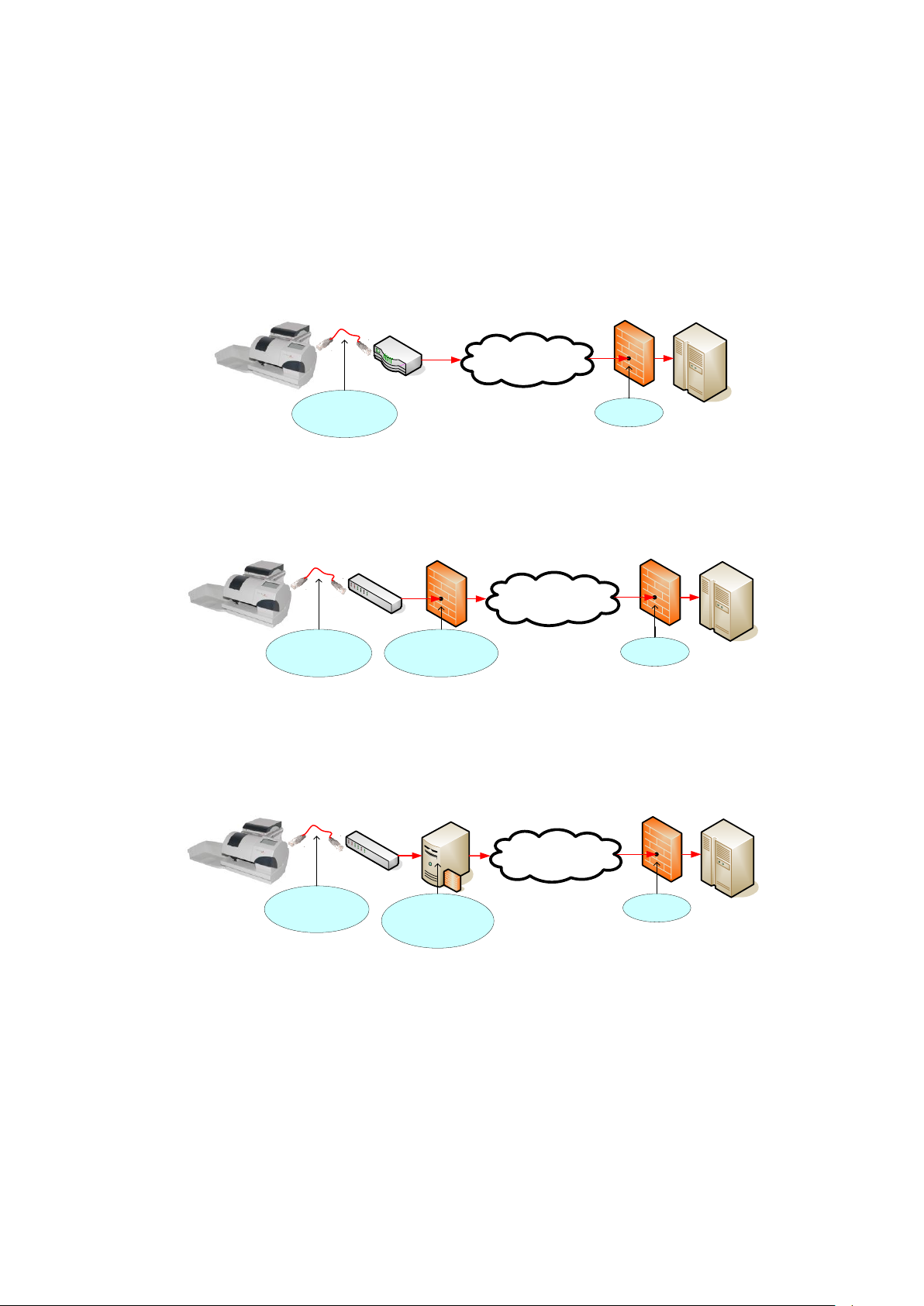
5SUPPORTED NETWORK INFRASTRUCTURE ...................................................................................7
6INFORMATION REQUIRED FOR MANUAL CONFIGURATION / PROXY CONFIGURATION ..........8
7INSTALLATION.................................................................................................................................8
8IP CONFIGURATION.........................................................................................................................9
8.1 Admin Login and Connection Settings .................................................................................... 10
8.2 Display Current Network Configuration .................................................................................. 12
8.3 DHCP...................................................................................................................................... 14
8.4 Static IP Address ..................................................................................................................... 15
8.5 No Proxy Server....................................................................................................................... 18
8.6 Proxy Server without Authentication ....................................................................................... 19
8.7 Proxy Server with Basic Authentication.................................................................................... 22
8.8 Connection Test...................................................................................................................... 25
8.9 Internet Connection Test ........................................................................................................ 26
8.10 Display IP Log.......................................................................................................................... 27
9TROUBLESHOOTING..................................................................................................................... 28
9.1 E0755..................................................................................................................................... 28
9.2 E0757..................................................................................................................................... 29
9.3 E0764..................................................................................................................................... 29
9.4 E0767, E0768, E0769, E076A................................................................................................. 30
9.5 E076B, E076C, E076D, E076E................................................................................................. 30
9.6 E076F ..................................................................................................................................... 31
9.7 E0771..................................................................................................................................... 31
9.8 E0772..................................................................................................................................... 32
9.9 E0773..................................................................................................................................... 32
9.10 E0774..................................................................................................................................... 33
9.11 E0750, E0751, E0752, E0762, E0763, E0765, E0766.............................................................. 33
10 APPENDIX ................................................................................................................................. 34
10.1 IP Configuration Questionnaire ............................................................................................... 34
10.2 Default IP Configuration ......................................................................................................... 35

1Introduction
This manual describes how to configure the franking system to connect via the Internet to the FramaOnline2 system.
Read this manual in line with the franking machine user manual. Refer to the franking machine user manual for
further information on safety, operation maintenance. The franking machine screens provided in this manual are for
reference only and may differ from country to country.
This manual requires enhanced knowledge about network technology. Speak to a qualified IT support person if you
feel uncomfortable with the network setup.
2Overview TCP/IP connection Frama Matrix F series
This chapter shall provide an detailed overview with regards to the requirements of the clients IT infrastructure to
operate a franking system of Matrix F series within the TCP/IP network. Always refer to the “IP configuration manual
for Matrix F series” which can be downloaded from www.frama.com
2.1 System requirements
An Ethernet network socket that connects to the Internet
The franking system must be able to communicate via TCP port 443 (https /SSL) to the URL
fo2.frama.com
Supported proxy server configuration (refer to section 2.2.2)
2.2 TCP/IP Specification of Frama Matrix F series TCP/IP port
2.2.1 Connection / Protocols
Ethernet 10 Base-T / 100 Base-T Auto Sensing, RJ45 socket
Internet protocol IPv4
Supports DHCP (standard) and Static IP Address Configuration
Note!
The Ethernet port used on Frama Matrix F series is only active and enabled during
connection with FramaOnline2!
2.2.2 Proxy Servers
Proxy Servers are supported without authentication or with basic authentication (username
and password)
Addressing of proxy server is supported using proxy server IP-Address and port number
Note!
Communication via Proxy Server with SSL Interception is not supported!
Due to security requirements, the franking system cannot connect through https proxy servers that
intercept the SSL encrypted communication.

2.3 FramaOnline2 Connection Procedure
The following steps are performed when the Frama Matrix F series franking systems connects to FramaOnline2
(fo2.frama.com).
Step
Action
Details
0
Pre-conditions to
initiate a connection
Manual process
The franking system user (the “user”) initiates a connection via the corresponding functions
“Inspection”, “Re-set” or by using the SmartShop
Automated process (Auto-Connect)
Automatically performed on a daily, weekly, monthly basis or other period (due to local
requirements)
1
Network initialisation
Franking system seals print head
Franking system enables its TCP/IP port (power on)
DHCP address mode
The franking system performs a DHCP broadcast request and waits for DHCP-
Server answer for about 60 seconds
Static IP-Address mode
The franking system uses the address settings configured in
Setup2/FramaOnline2/Connection/Network Setup
2
Connection to
fo2.frama.com
The Franking system connects to port 443 on fo2.frama.com.
In any case communication via a proxy server is mandatory, the parameters in
Setup2/FramaOnline2/Connection/Network Setup)
will be used. Please note the supported proxy server configurations
The franking system communicates through SSL/https tunnel with FramaOnline2.
Data exchange starts.
3
Termination of
connection to
fo2.frama.com
After the successful data exchange with Framaonline2 the franking system
terminates communication to port 443 on fo2.frama.com
The franking system disables the TCP/IP port (power off)
The franking system displays the communication result to the user
3System Requirements
In order to connect your franking system with the FramaOnline2 system, you minimally require the following:
Infrastructure:
An Ethernet network socket that connects to the Internet
The franking system must be able to communicate via TCP port 443 (https / SSL) to the URL fo2.frama.com
Proxy server
The franking system supports connection via a http proxy server with basic authentication or without
authentication
Note!
Communication via Proxy Server with SSL Interception is not supported!
Due to security requirements, the franking system cannot connect through a https proxy server
that intercepts the SSL encrypted communication.

Tip!
Proxy servers using SSL-interception require a specific rule in order to allow transparent
communication (franking system via F-Link to FramaOnline) via https port 443.
The specific rule grants correct identification of FramaOnline2 (https certificate) for the franking
system.
4Quick-Start Installation and Configuration
If you connect your franking system to a so-called SOHO (Small Office / Home Office) infrastructure via a DSL router to
the internet, installation and configuration of the franking system is very simple and straight forward:
Preconditions:
(DSL) Router device connecting to the internet
DHCP enabled on router and access to internet from LAN not restricted
Procedure:
Make sure that the franking system is switched off.
Connect the green framed RJ-45 socket labelled „LANG4“ of the franking system with a free LAN-port on your
router using a standard CAT5 RJ-45 network cable
Power on the franking system
Check the connection as described in section 8.8.
Tip!
Perform the required installation connect as described in your franking system user manual to
trigger the initial connection to the FramaOnline2 system.
Perform any subsequent inspection or re-set connections as described in your franking system
user manual.
Refer to the following sections in this manual for detailed information on configuration in case your network does not
meet the pre-conditions for a quick start installation and configuration.

5Supported Network Infrastructure
In order to connect a Frama franking system to the FramaOnline2 system via the Internet the following network
structures are supported:
Simple Network Layout:
Your franking system is connected via a network router device (e.g. a DSL router) to the internet.
Internet
FramaOnline2Your (DSL) Router
Connect your franking
system with CAT 5 network
cable to your (DSL) router fo2.frama.com
TCP port 443
Your Frama
Franking System Frama Firewall
Typical Company Network Layout without Proxy Server
Your franking system is connected via a company network and a routing device to the internet.
Internet
FramaOnline2
Connect your franking
system with CAT 5 network
cable to your network fo2.frama.com
TCP port 443
Your Frama
Franking System Frama Firewall
The IP address of your
franking system must have
access to: fo2.frama.com
TCP port 443
Your Firewall
Your Network
Typical Company Network Layout with Proxy Server
Your franking system is connected via a company network and a proxy server to the internet. All traffic from the
company internal network is routed via the proxy server to the internet.
Internet
FramaOnline2
Connect your franking
system with CAT 5 network
cable to your network fo2.frama.com
TCP port 443
Your Frama
Franking System Frama Firewall
The franking system is
configured to use a proxy and
connect via the proxy to
fo2.frama.com
TCP port 443
Your Proxy Server
Your Network
Addressing Mode
Independently of the physical or logical network layout, the addressing mode defines how the franking system does
determine the IP address to use for network communication. The franking system supports DHCP and static IP address
mode.
DHCP: In DHCP addressing mode, the franking system is automatically assigned to an IP address, subnet mask,
default gateway and DNS-Server from a DHCP server.
Static IP Address: In this mode, you are required to configure the static IP address, subnet mask, default
gateway and DNS-Server. If your network requires the franking system to use static IP address, your IT personnel
shall be able to provide you with the values required.

6Information required for manual configuration / proxy
configuration
Before you start the configuration of the IP parameters of the franking system, please ask your IT personnel for the
following information:
What addressing mode must be used?
The addressing mode defines how your franking system determines IP address and related parameters to be able to
communicate in your local network. The franking system supports DHCP and static IP address mode:
Static IP Address: If your network requires a static IP address the following additional information is required:
IP Address Format: nnn.nnn.nnn.nnn Example: 192.168.2.36
Subnet Mask Format: nnn.nnn.nnn.nnn Example: 255.255.252.0
Default GatewayFormat: nnn.nnn.nnn.nnn Example: 192.168.2.1
DNS-Server Format: nnn.nnn.nnn.nnn Example: 168.192.178.25
DHCP: In DHCP addressing mode, the franking system is automatically assigned to an IP address, subnet mask,
default gateway and DNS-Server from a DHCP server.
Do you have to configure a Proxy Server?
In case your local network configuration requires all connections to be routed via a proxy server you need to get the
following information:
Proxy Server IP Address: What is the IP address of the proxy server?
Proxy Server Port Number: What port number has to be used on the proxy server?
Authentication Mode: The franking system support the following proxy authentications:
No authentication: No user and password is required to connect through the proxy
Basic authentication: If the proxy requires basic authentication you have to be given a username and
password to connect through the proxy.
Tip!
Use the form provided in section 10.1 to get the required information from your IT personnel.
7Installation
Connect your franking system via the provided RJ45 network cable with your local network:
Use the green framed RJ-45 socket labelled with „LANG4“ at the back of the franking system.
Note!
The Ethernet port on the franking system is only active during a connection to the FramaOnline2
system. Use the function “Connection Test” described in section 8.8 to power the Ethernet port
and to check the connection.

8IP Configuration
Please use the questionnaire provided in section 10.1 to ask your IT personnel for the required information for
configuring the IP parameters in your franking system.
Section 8.1 describes how to login as admin user and to navigate to the network configuration screen.
The following table shows you, what configuration has to be done on the franking system:
IP Configuration Values
Description
Required steps for new
installation
How to assure
that the IP
parameters are
set correctly
DHCP and no proxy server
This is the default
configuration of the IP
parameters in the
franking system
Nothing!
Section 8.3 and
8.5
DHCP and Proxy Server
DHCP is set by default,
you only have to
configure the proxy
server.
Section 8.6 when no username/
password is provided for the proxy.
Section 8.7 when a username/
password is required for the proxy.
Section 8.3 and
8.6 or 8.7
Static IP Address and no
proxy
You have to configure
the parameters for static
IP configuration.
Section 8.4
Section 8.4 and
8.5
Static IP Address and Proxy
Server
You have to configure
static IP and the proxy
server
Section 8.4
AND
Section 8.6 when no username/
password is provided for the proxy.
OR
Section 8.7 when a username/
password is required for the proxy.
See Section 8.4
and 8.6 or 8.7
Note!
The screen texts of the franking system user interface are translated to the local language
depending on the country and settings of the franking system.
In the following pages button referenced in the description are shown in when they will
appear in the local language. Buttons referenced in normal font are always displayed in English.
Example:
“FramaOnline2” references the button which in all languages is shown as
“” references the button which e.g. in German is translated as:

8.1 Admin Login and Connection Settings
Description
Matrix F12
Matrix F22 –Matrix F82
Power on the franking system
Select the Admin Login
Enter the pin code
Select the Button “i”
Select the tool button in the upper right
corner.
Select the button “”

Select the button “FramaOnline2”
Select the Button “ ”
Select the button “Network Setup”
In the network configuration menu (2
pages), you can
define the network settings of the
franking system,
display the actual configuration,
trigger a connection test,
trigger an internet connection test and
display the connection log.

8.2 Display Current Network Configuration
Description
Matrix F12
Matrix F22 –Matrix F82
Power on the franking system, login as
“Admin” and navigate to the network
settings page refer to section 8.1
F12: Go to the second page of the
network configuration screen with the
button “ ”.
F22 –F82: Press the button “IP Config
Summary”.
The franking system displays the current
IP configuration:
First sample: DHCP and no proxy
2nd sample: DHCP and proxy with
authentication

3rd sample: Static IP and no proxy
4th sample: Static IP and proxy with
authentication

8.4 Static IP Address
Note!
Due to the limited space in the buttons, some of the static IP parameters may not be display
completely in the button. But you are always able to check and see the complete value of a
parameter, by pressing the button.
Description
Matrix F12
Matrix F22 –Matrix F82
Power on the franking system, login as
“Admin” and navigate to the network
settings page refer to section 8.1
Press the button “Address Type” until it
displays on the second line “STATIC”
When switching from
DHCP to static IP Address,
the franking system will
always reset the IP address
to 0.0.0.0 and use the last
values known for the
other parameters.
Press the button “IP Address ….” to
manually set the IP address
Enter the IP address to the value
defined by your IT personnel.
Complete the entry by pressing “ ”.
The franking system will only accept valid
IP addresses:
Format: n.n.n.n
0 ≤n ≤ 255

Press the button “Subnet Mask”.
Enter the subnet mask to the value
defined by your IT personnel.
Complete the entry by pressing “ ”.
The franking system will only accept valid
subnet masks:
Format: n.n.n.n
0 ≤n ≤ 255
Press the button “DNS-Server”.
Enter the DNS Server IP address to the
value defined by your IT personnel.
Complete the entry by pressing “ ”.
The franking system will only accept valid
subnet masks:
Format: n.n.n.n
0 ≤n ≤ 255
Press the button “Gateway”.

Enter the default gateway IP address to
the value defined by your IT personnel.
Complete the entry by pressing “ ”.
The franking system will only accept valid
subnet masks:
Format: n.n.n.n
0 ≤n ≤ 255
Now you have set all parameters for a
static IP address configuration.
Now make sure to configure the proxy
server correctly:
See section 8.5 when no proxy server
must be set.
See section 8.6 to configure a proxy server
without authentication
See section 8.7 to configure a proxy server
with basic authentication

8.5 No Proxy Server
Description
Matrix F12
Matrix F22 –Matrix F82
Power on the franking system, login as
“Admin” and navigate to the network
settings page refer to section 8.1
F12: Go to the second page of the
network configuration screen with the
button “ ”.
When the button “Proxy Server” shows
“OFF” in the second line The franking
system uses no proxy server and you are
done.
When the button “Proxy Server” shows
an IP address in the second line, then the
franking system is configured to use a
proxy server
Press the button “Proxy Server”.
Press the button “Proxy Server ON”to
disable the proxy server configuration.
Press the button “Esc” to go back to the
network configuration screen.

8.6 Proxy Server without Authentication
Description
Matrix F12
Matrix F22 –Matrix F82
Power on the franking system, login as
“Admin” and navigate to the network
settings page refer to section 8.1
F12: press the button “ ” to navigate
to the second page
Press the button “Proxy Server” to use a
proxy server to connect via internet to
the FramaOnline2 system.
To set (or change) the proxy port
number, press the button “Proxy Port”
and …
Enter (or change) the port number for
the proxy port and complete the entry
with the button “ ” or “OK”.
Press the button “Proxy Adr.” and …

Enter (or change) the proxy server IP
address to the value defined by your IT
personnel.
Complete the entry by pressing “ ”.
The franking system will only accept valid
IP addresses:
Format: n.n.n.n
0 ≤n ≤ 255
Press the button “Username” to check
that no username is set …
Delete an eventually set username by
pressing “CE” until the input field is
empty.
Complete the entry by pressing “ ”.
Press the button “Password” to check
that no password is set …
Delete an eventually set password by
pressing “CE” until the input field is
empty.
Complete the entry by pressing “ ”.
Note: Password entry is not in clear text,
all characters entered are displayed as
“*”.
Other manuals for Matrix F Series
1
Table of contents
Other Frama Postal Equipment manuals

Frama
Frama Fn 5 Series User manual

Frama
Frama Access B400 User manual

Frama
Frama Access B400 User manual

Frama
Frama MATRIX F22 Installation instructions

Frama
Frama Matrix F4 User manual

Frama
Frama Fx 5 Series User manual

Frama
Frama Fx 7 Series User manual

Frama
Frama Access B400 User manual

Frama
Frama Matrix F32 User manual

Frama
Frama Fs 3 Series User manual