6
ACHTUNG:
ACHTUNG:
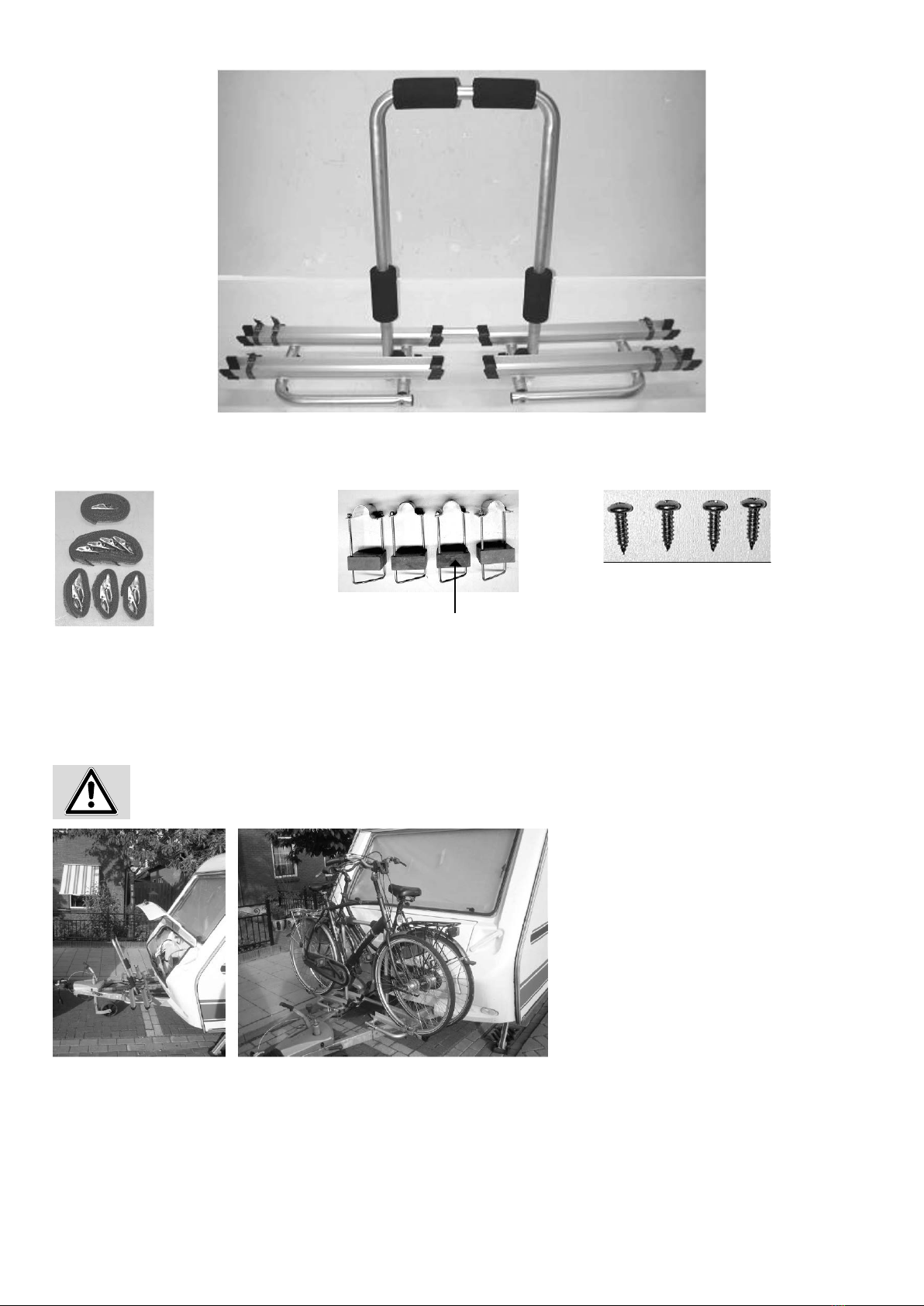
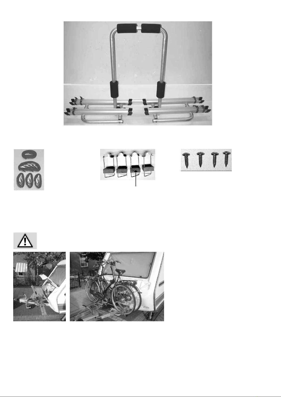
Legen Sie den Sicherheitsgurt durch die Fahrradrahmen und um den U-Bügel herum und ziehen den Sicherheitsgurt fest an.
• Beachten Sie unbedingt die max. Stützlast Ihrer Anhängerkupplung, bei Beladung des Deichselträgers. Achtung: Der Lenkeinschlag darf nicht behindert
werden.
• Die Prolbreite der Wohnwagendeichsel darf maximal 45 mm betragen.
• Achtung: Der Lenkeinschlag darf nicht behindert werden.
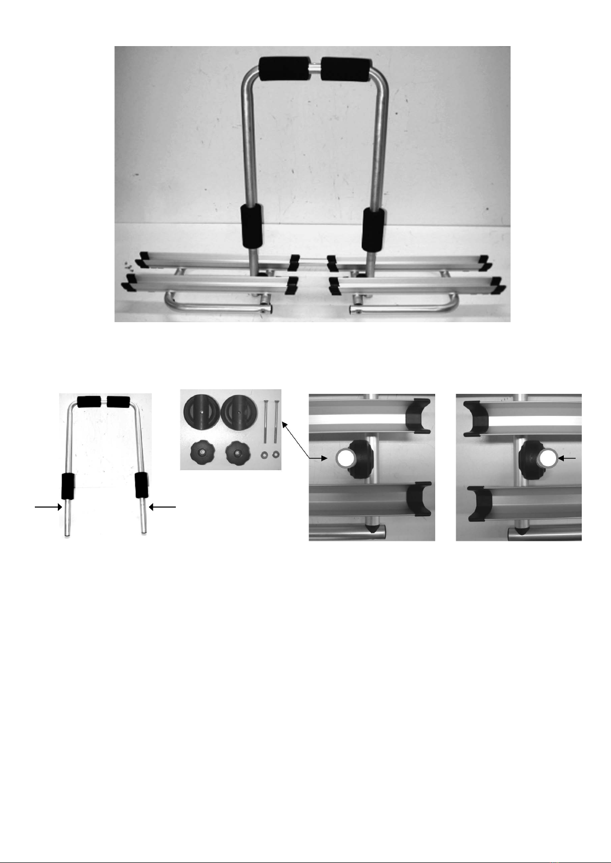
• Die korrekte Befestigung und Montage des Deichselträger ist nur dann gegeben, wenn die Abstandsmaße der Deichselprole zwischen 380 mm-740 mm
liegen.
• Die erforderliche Mindestlänge der Deichsel beträgt 1400 mm (siehe Foto)
• Kurze Deichseln sind für eine Montage nicht geeignet.
• Kontrollieren Sie vor jedem Fahrtantritt und zwischendurch regelmäßig den festen Sitz desTrägers auf der Deichsel und auch die Befestigung der Räder auf
dem Deichselträger, um etwaige Beschädigungen der Befestigungselemente frühzeitig zu erkennen und zu beheben!
• Bei Beladung muss der Sicherheitsgurt befestigt werden!
• Reduzieren Sie bei Seitenwind die Fahrgeschwindigkeit.
• Achten Sie darauf, dass Sie keineTeile vom Fahrrad verlieren können (Luftpumpe, Körbe, Klingel etc.)
• Vermeiden Sie ruckartiges Bremsen Beschleunigen und Lenkbewegungen.
• Bei Austausch vonTeilen immer nur Originalteile verwenden!
• Für die ordnungsgemäße und sichere Montage die Montageanweisung genau befolgen. Bei Zweifeln in Hinblick auf diese Anweisungen den Händler oder
direkt den Hersteller um weitere Informationen bitten.
• Der Hersteller und der Händler haften nicht für Schäden an Sachen oder Personen aufgrund einer unsachgemäßen Montage oder eines unsachgemäßen
Gebrauchs.
• Das Produkt wurde geprüft und auch unter extremen Bedingungen erprobt.
• Daher können wir bei fachgerecht ausgeführter Montage Fehlfunktionen ausschließen.
• Zu Ihrer eigenen Sicherheit sollten Sie denTräger und die dazu gehörende Ladung regelmäßig kontrollieren, weil Sie nach § 23 der STVO dazu verpichtet sind
und im Schadensfall haftbar gemacht werden.
• Der Hersteller und der Händler haften nicht für Sach-Schäden Personen-Schäden, aufgrund einer unsachgemäßen Montage oder eines unsachgemäßen
Gebrauchs.
• Das Produkt wurde geprüft und auch unter extremen Bedingungen erprobt, wobei es in Hinblick auf Sicherheit und Halt gute Ergebnisse erbrachte. Daher
können wir bei fachgerecht ausgeführter Montage Fehlfunktionen ausschließen.
SICHERHEITSHINWEISE UNBEDINGT BEACHTEN!
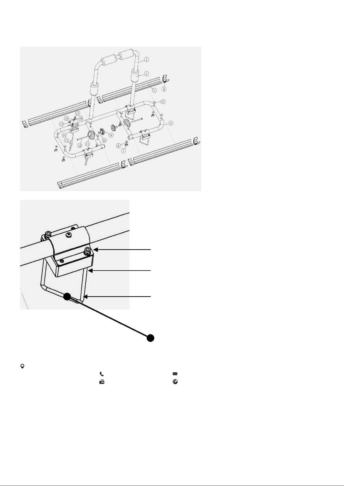
Sicherheitsgurt Radbefestigung