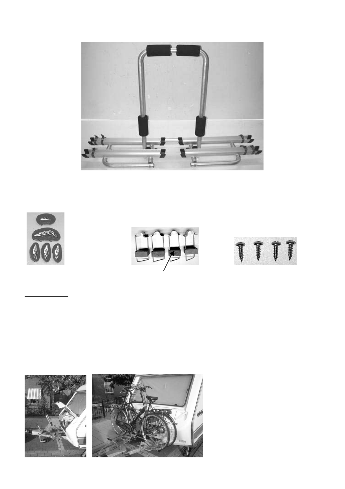
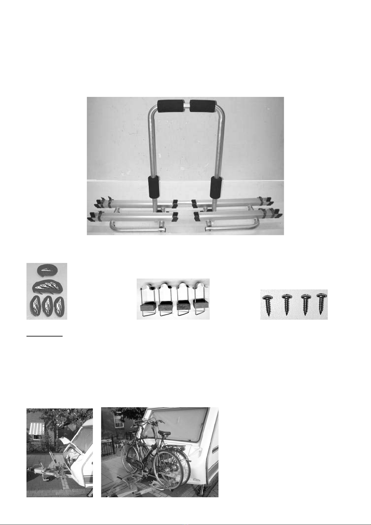
Die erforderliche Mindestlänge der Deichsel beträgt 1400 mm (siehe Foto)
Kurze Deichseln sind für eine Montage nicht geeignet.
Kontrollieren Sie vor jedem Fahrtantritt und zwischendurch regelmäßig den festen Sitz des Trä-
gers auf der Deichsel und auch die Befestigung der Räder auf dem Deichselträger, um etwaige
Beschädigungen der Befestigungselemente frühzeitig zu erkennen und zu beheben!
Bei Beladung muss der Sicherheitsgurt befestigt werden!
Reduzieren Sie bei Seitenwind die Fahrgeschwindigkeit.
Achten Sie darauf, dass Sie keine Teile vom Fahrrad verlieren können (Luftpumpe, Körbe,
Klingel etc.)
Vermeiden Sie ruckartiges Bremsen Beschleunigen und Lenkbewegungen.
Bei Austausch von Teilen immer nur Originalteile verwenden!
Für die ordnungsgemäße und sichere Montage die Montageanweisung genau befolgen. Bei
Zweifeln in Hinblick auf diese Anweisungen den Händler oder direkt den Hersteller um weitere
Informationen bitten.
Der Hersteller und der Händler haften nicht für Schäden an Sachen oder Personen
aufgrund einer unsachgemäßen Montage oder eines unsachgemäßen Gebrauchs
Das Produkt wurde geprüft und auch unter extremen Bedingungen erprobt.
Daher können wir bei fachgerecht ausgeführter Montage Fehlfunktionen ausschließen.
Zu Ihrer eigenen Sicherheit sollten Sie den Träger und die dazu gehörende Ladung regelmäßig
kontrollieren, weil Sie nach § 23 der STVO dazu verpflichtet sind und im Schadensfall haftbar
gemacht werden.
Der Hersteller und der Händler haften nicht für Sach-Schäden Personen-Schäden, aufgrund
einer unsachgemäßen Montage oder eines unsachgemäßen Gebrauchs.
Das Produkt wurde geprüft und auch unter extremen Bedingungen erprobt, wobei es in Hinblick
auf Sicherheit und Halt gute Ergebnisse erbrachte. Daher können wir bei fachgerecht ausge-
führter Montage Fehlfunktionen ausschließen.
Sehr verehrter Kunde,
vielen Dank, dass Sie sich für dieses Produkt entschieden haben.
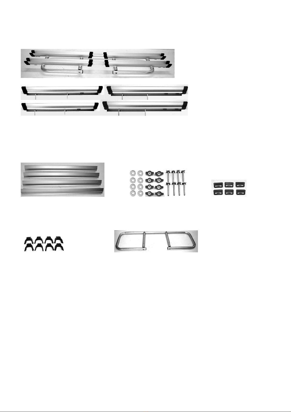
Dieser Deichselträger wurde auf Vollständigkeit hin überprüft. Der Deichselträger ist aus Alumi-
nium mit einem Eigengewicht von ca. 4 kg (ohne Befestigungsteile). Mit Befestigungsteile be-
sitzt der Träger ein Eigengewicht von ca. 6 kg. Die Befestigungsteile sind aus Edelstahl und
Kunststoff!
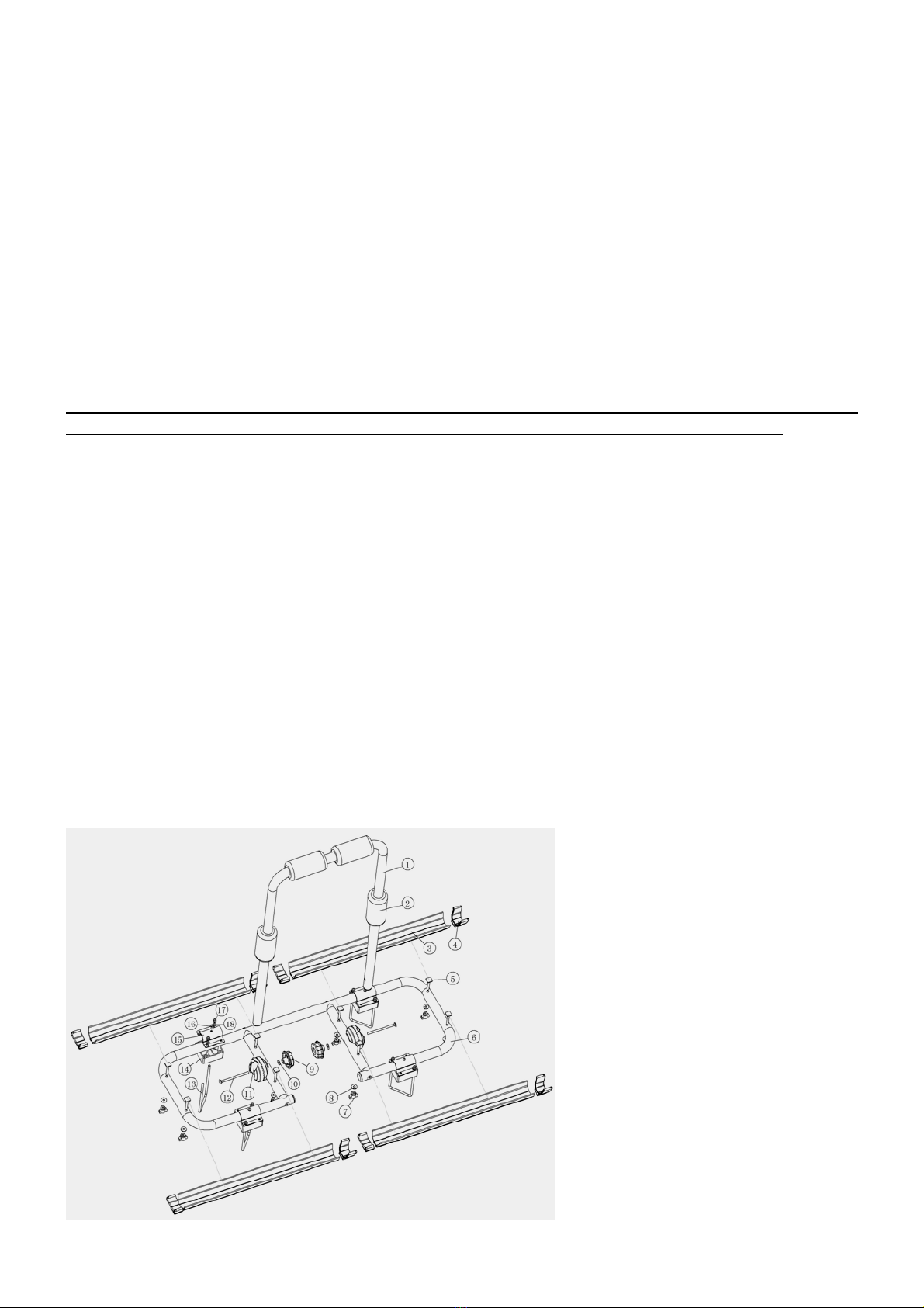
Explosionszeichnung