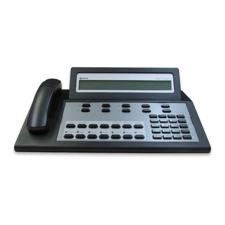
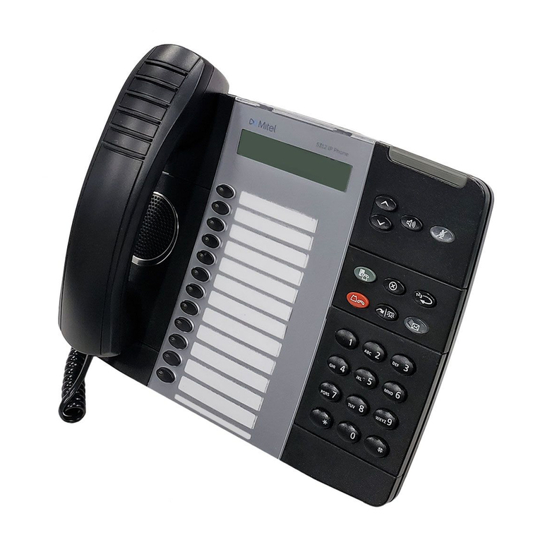
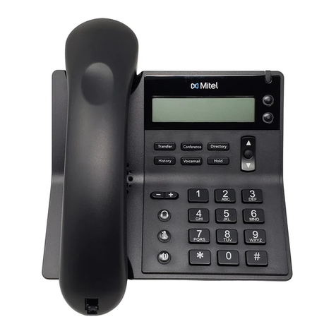
Mitel SX-200 Instructions for use

SX-ZUO@
DIGITAL PABX
Generic 1005
Practices Index

NOTICE
The information contained in this document is believed to be accurate in all respects
but is not warranted by
Mite1
Corporation (MITELB). The information is subject to
change without notice and should not
be
construed in any way as a commitment by
Mite1
or any of its affiliates or subsidiaries.
Mite1
and its affiliates and subsidiaries
assume no responsibility for any errors or omissions in this document. Revisions of
this document or new editions of it may be issued to incorporate such changes.
Generic
1005
Practices Index
.
. .

1
.
GENERAL
This Section contains a list of Practices for the SX-2008 DIGITAL Private Automatic Branch
Exchange, with the following software variants: Generic 1001, Generic 1002, Generic 1003,
Generic
1004,
Generic 1005, Generic 1005 FPKGI , and Generic 1005 LIT96.
Documentation Index
1.1
The SX-200 DIGITAL PABX documentation is contained in 2 volumes as follows:
Volume 1
-
Features and Services, Hardware
(9109-096001-NA)
contains a
system description, feature operation information and hardware
descriptions of circuit cards and peripheral equipment.
Volume 2
-
Installation and Administration (9109-096-002-NA) contains system
installation, testing, data entry information, engineering, troubleshooting
and maintenance information.
9109496-00o-NA
Issue 1
Revision
0
1

Generic 1005 Practices Index
Table l-l Generic 1005 FDl Practices Index
IOLUME 1
Practice Number
3109-096-00O-NA
3109-096-l OO-NA
3109-096-l
05-NA
3109-096-22O-NA
3109-096-221
-NA
3109-096-23O-NA
3109-09645O-NA
3109-09&602-NA
3109-096-62O-NA
3109-096-625-NA
9109-096-I
25-NA
9109-096126-NA
VOLUME 2
Practice Number
9109-09~0O-NA
9109-096203-NA
9109-09620O-NA
9109-096-21 O-NA
9109-09%35O-NA
9109-096-3514A
9109-096-353-NA
9109-096-355-NA
9109496-l
8O-NA
Features and Ssrvices, Hardware
910Q-O9~01-NA
Title
Generic 1005 Practices Index
General Description
Features Description
Automatic Route Selection and Toll Control
Station Message Detail Recording
Tenanting
Traffic Measurement
Hotel
/
Motel Feature Package Description
ACD TELEMARKETERB Application Package
Automated Attendant Application Package
Circuit Card Descriptions
Peripheral Devices
Installation and Administration 910Q-O96-002-NA
Title
Generic 1005 Practices Index
Safety Instructions
Installation Information
Customer Data Entry
Troubleshooting
W-232 Maintenance Terminal
General Maintenance Information
Field-Replaceable Units
Engineering Information

SX-200@DIGITAL PABX
-General
Description
mt
@-Tmdemarko(MltelcoQomllon.
0
Copyrlgtd
lea2,
Yltel
corpomuon.
All
rlghls
msewed.
PrInted In
Canada.
8
MITEL

General Description
Revision 0
9109-096lO&NA
Issue 1

IMPORTANT SAFETY INSTRUCTIONS
pq
Failure to follow all instructions may result In improper
equlpment operation and/or the risk of electric shock.
l
Only qualified personnel should install and service this product.
9
Read all instructions before attempting to install or use this product.
l
Install all assemblies using the procedures described in this Practice.
l
Configure this product with only the assemblies specified in this Practice.
l Grounding circuit continuity is vital for safe operation of telecommunication
equipment. Never operate telecommunication equipment when the grounding
conductor is disconnected. Ensure the grounding conductor is installed before
connecting telecommunication cabling to any system.
EXPLANATIONS OF SYMBOLS AND NOTICES
A
A lightning bolt within
an
equilateral triangle indicates the presence of
an uninsulated ‘dangerous voltage’ within the products enclosure.
The uninsulated voltage represents a significant risk of electric shock
to people.
DANGEROUS
VOLTAGE
INSTRUCTIONS
.
PROTECTNE
GROUNDING
TERMINAL
An exclamation mark within an equilateral triangle indicates that
important operating and servicing instructions accompany the
product.
A ground symbol within a circle identifies the terminal for connection
to an external protective conductor. The terminal must be connected
to earth ground prior to making any other connections to the
equipment.
1DANGER 1
I I
I
I
1WARNING
1
I
I
I
f
1CAUTION
1
Danger indicates an imminently hazardous situation which, if not
avoided, will result in death or serious injury.
Warning indicates a potentially hazardous situation which, if not
avoided, could result in death or serious injury.
Caution indicates a potentially hazardous situation which, if not
avoided, may result in minor or moderate injury and/or damage to the
equipment or property.
9109496-l OO-NA
Issue 1 Revision 0

General Description
iv
Revision 09109-096-l OO-NA Issue 1

Table of Contents
I,
INTRODUCTION
General...................................................................
100 l-l
Reasonforissue...............................................,.,..........
100 l-l
2. SYSTEM OVERVIEW
General
................................................................... 100 2-l
Hardware Configurations
..................................................... 100 2-l
Physical Characteristics
...................................................... 100 2-3
System Reqrirements
......................................................
t
100 2-3
Software Configurations and Supported Peripheral Devices
.......................... 100 2-4
Generic1001
........................................................... 100 2-4
Generic1002
...........................................................
Generic1003
..................................................... ......
Generic1004
...........................................................
Generic 1005 FPKG 1 and Generic 1005 LIT96
................................
Generic1005
...........................................................
00
2-4
00 2-4
00 2-5
00 2-5
00 2-5
VoiceCapabilities
........................................................... 100 2-8
Data Capabilities
..................................... ...................... 100 2-7
Customer Data Entry (CDE)
................................................... 100 2-8
3. PHYSICAL DESCRIPTION
General
................................................................... 100 3-l
Control Cabinet for 336-,
456,
and 48O-Pott Configurations
......................... 100 3-l
336-par-t Control Cabinet
.................................................. 100 3-l
456-part Control Cabinet
.................................................. 100 3-l
48O-port Control Cabinet
..................................................
Analog Peripheral Cabinet
(456
and 48O-Por-t Configurations only)
...................
672-Part Control Cabinet
.....................................................
672-Part Peripheral Cabinet
..................................................
SX-200B
FD Control Cabinet
.................................................
00 3-2
00 3-2
00 3-6
00 3-6
00 3-9
SX-200 FD Peripheral Cabinet
................................................ 100 3-9
Power Fail Transfer
......................................................... 100 3-9
-
MaintenancePanels
......................................................... 100 3-12
PowerSupplies..........................................................~
.. 100 3-12
4. HARDWARE
OVERVlEW
General
................................................................... 100 4-l
336,456,480-,
and
672-
Port Configurations
................................... 100
4-l
SX-200 FD System configuration
............................................... 100 4-2
ControlCabinet
......................................................... 100 4-2
PeripheralCabinet
....................................................... 100 4-3
Peripheral Interface Cards
.................................................... 100
4-4
5. SOFTWARE OVERVIEW
General...................................,...............................
1005-l
9109-096-l OO-NA Issue 1 Revision 0
V

General Description
PhysicalLayer
............................................................. 100 5-1
SchedulingLayer
........................................................... 100 5-l
Communications Layer
....................................................... 100
5-l
MessageSubsystem
........................................................ 100
5-l
Device Input/Output Layer
.................................................... 100
5-2
Utilities Layer
.............................................................. 100
5-2
Main Control Processor Applications Software
..................................... 100
5-2
Peripheral Control Processor Software
.......................................... 100
5-2
Database
................................................................. 100 5-2
6. MAINTENANCE
General
................................................................... 100 6-l
Maintenance Objectives
...................................................... 100 6-l
RS-232 Maintenance Terminal
................................................. 100 6-l
DiagnosticLogFiles
......................................................... 100 6-l
TypesofDiagnostics
......................................................... 100 6-2
7. FEATURES . . . . . . . . . . . . . . . . .
e
. . . . . . . . . . . , . , , , , . . . , , . . . . . . . . . . . , , , . . . . . . . , loo
7-1
List of Figures
I
Figure 2-l SX-200 DIGITAL PABX Bay and Slot Assignment
-336-Part
Configuration . . .
100 2-9
Figure 2-2 SX-200 DIGITAL PABX Bay and Slot Assignment
-456-Part
Configuration , . ,
100 2-l 0
Figure 2-3 SX-200 DIGITAL PABX Bay and Slot Assignment
-
48CkPort Configuration , . ,100 2-11
Figure 24
SX-200 DIGITAL PABX Bay and Slot Assignment
-
672-Part Configuration , , ,
100 2-12
Figure 25
SX-200 FD Control Cabinet and Peripheral Cabinet
-
Bay and Slot Assignments 100 2-l 3
Figure 3-l Universal Control Cabinet with Digital Peripheral Shelf . , . . . , . . . . , , , . . , , , , .
100 3-3
Figure 3-2 Universal Control Cabinet with Analog Peripheral Shelf , . . , . . . . . . , . . . . . . . .
100 34
Figure 3-3 Analog Peripheral Cabinet . . . , . . . . . . . . . . , . . . . . . . .
I
. . . . , . . . . . . . . , . . . .
100
3-5
Figure 3-4 672-Part Control Cabinet . . . , , , . . . . . . . . . , . . . . . . . . . . . . . , , . . . . . . . , . . . .
100 3-7
Figure 3-5 672-Part Peripheral Cabinet , , . . . . . . . . . . , . . . . . . . . . . . . . . . . . . . . . . . . . . ,
100 3-8
Figure 3-6 SX-200 FD Control Cabinet . . . . . . . . . . .
=
. . . . . . . . . . . . . . . . . . . . . . . . . . . . ,
100 3-l 0
Figure 3-7 SX-200 FD Peripheral Cabinet . . . . . . . . . . . . . . . . . . . . . . . . . . . . . . . . . . , , . . 100 3-11
Table 2-l Physical Characteristics
............................................. 100 2-3
Table 2-2 Environmental Requirements
......................................... 100 2-3
Table 2-3 Electrical Requirements
............................................. 100 2-3
Table 4-l
FIMLEDs
.....................................................
..lO
0 4-3
Table 7-l PABX Features
................................................
..lO
0 7-l
vi
Revision 0
9109-096-l
OO-NA Issue 1
1
’
INTRODUCTION
General
1.1
This practice describes the SX-20&$ DIGITAL PABX. It provides an overview of
.hardware
features, as well as a summary of environmental, electrical, and
maintenance considerations. Refer to the following sections for more detailed
descriptions of related information:
0
Practice 9109--096105-NA, Features Description
l
Practice 9109-096-I 80-NA, Engineering Information
l
Practice
910949~200-NA,
Installation Information
Reason for issue
1.2
This practice describes the SX-200 DIGITAL PABX with seven Generic software
loads. This is the first issue with Generic 1005 FPKG 1 software, Generic 1005 LIT
96 software, and Generic 1005 software.
9109-09~10O-NA
Issue1 Revision 0 100 l-l

General Description
100 1-2
Revision 09109-096-l OO-NA Issue 1

2
.
SYSTEM OVERVIEW
General
2.1
The SX-200 DIGITAL PABX is a microprocessor controlled telephone system that
,handlesboth voice and data switching for installations up to 500 lines. The system is
available in various hardware configurations ranging from 336 to 672 ports, All
configurations of the system are electrically compatible with most
’
l
single line telephones,
l
MITEL@
proprietary sets,
l
key telephone systems,
l
PABX telephone systems, and
l
central office exchanges.
The following subsections outline the various hardware configurations and the
software versions (generics) available for each configuration. Refer to Section NO TAG
of this practice for additional information about the hardware configurations, and to
Section NO TAG for an overview of the software structure. Table 2-1 describes
physical characteristics of the PABX.
Figure 2-1 through Figure 2-5 show the maximum number of trunk and line cards that
each configuration can accommodate.
Hardware Configurations
2.2
The SX-200 DIGITAL PABX is available in five different hardware configurations:
9
336 ports in a single cabinet,
0
456 ports in two cabinets (upgrade to existing SX-200 PABX only),
l
480 ports in two cabinets (existing SX-200 DIGITAL
PABXs
only),
l
672 ports in two cabinets, and
0
672 ports in seven Peripheral cabinets (96 ports/cabinet) supported by a Control
cabinet (SX-200 FD system).
The
336
and 672-par-t configurations use fully digital control circuits, line cards, and
trunk cards. The
456
and 480-port configurations are hybrid systems, using digital
control circuits with a mixture of digital and analog peripheral cards. Customers with
installed SX-200 analog systems may upgrade to the latest in digital switching
technology (456-pat-t)while retaining their investment in cabinets, power supplies, line
cards, and trunk cards.
9109-096-10O-NA
Issue1
Revision
0
100 2-l

General Description
The
336port
configuration consists of a single cabinet with four fully digital card bays
for a maximum of 336 digital peripheral ports. This configuration is used for new
installations rather than upgrades,
The
456port
configuration combines a digital Control cabinet with an analog
peripheral cabinet. The
456port
configuration has five card bays offering a maximum
of 240 digital and 216 analog peripheral ports.
Note: The 456-part configuration is available only as an upgrade. Customers can upgrade their
installed
SX-200
PABX to an SX-200 DIGITAL PABX by adding a digital Control cabinet
to the existing analog cabinet.
The
480-port
configuration is similar to the
456port
configuration in that it combines
a digital control cabinet with an analog peripheral cabinet. The
480-port
configuration
has five card bays offering a maximum of 144 digital and 336 analog peripheral ports.
Note: The 48O-port configuration is no longer available for new installations. However, an
installed 48O-port SX-200 PABX may be upgraded with new software Generics.
The 672-port,
2-cabinet
configuration has seven digital card bays providing a
maximum of 672 digital peripheral ports. This configuration is used for both new
installations and upgrades to existing
336port
configurations. Since this system
accepts only digital peripheral cards, it is recommended for sites that use data features
extensively.
The SX-ZOO FD system consists of one Control cabinet and up to seven Peripheral
cabinets, Each Peripheral cabinet provides up to 96 ports, giving a combined total of
672 ports for a fully configured system.
Fiber optic cables connect the Control Cabinet with the Peripheral Cabinets. The
Peripheral Cabinets can be located up to 1 km from the Control Cabinet, allowing the
system lines (extensions) and trunks to be physically distributed among several remote
locations.
100 2-2
Revision 0
9109-098-l
OO-NA
Issue 1

System Overview
Physical Characteristics
Table 2-l Physical Characteristics
336,45&,
46s
and
672-
Port Configurations
Height Per Cabinet 96.0 cm 38.0 inches
Width Per Cabinet 60.0 cm 23.5 inches
‘Depth Per Cabinet 70.0 cm 27.5 inches
.:
Weight Fully Loaded 230 kg 500 pounds
SX-200
FD System Configurations
Height Per Cabinet 48.0 cm 19.0 inches
Width Per Cabinet 22.9 cm 9.0 inches
Depth Per Cabinet 42.0 cm 16.5 inches
Weight Fuliy Loaded 151 kg 333 pounds
System Requirements
2.3 The environmental and electrical requirements for the SX-200 DIGITAL PABX are
shown in Table 2-2 and Table 2-3 respectively.
Table 2-2 Environmental Requirements
Operating Temperature
10
to40°
c
5Oto104”F
Storage Temperature
-20 to 50” c
-4to122”F
Relative Humidity (Operating) (non- 20 to 80% 20 to 80%
condensing)
Relative Humidity (Storage)
(non-
10
togo% 10to90%
condensing)
Table 2-3 Electrkal Requirements
AC Input Voltage
AC Input Voltage
AC Input Frequency
AC Input Power
DC Output Power
Reserve Power
102
-
135
Vat
(115 v
-
9109-008-OOO-SA)
204
-
270
Vat
(230 v
-
9109-008-002-NA)
47-63 Hz
125 Watts RMS for each bay
100 Watts for each bay
Uninterruptable Power Supply (or Battery Backup Unit in
analog Peripheral cabinet only)
9109-096-l OO-NA Issue 1
Revision 0
100 2-3

General Description
Software Configurations and Supported Peripheral Devices
2.4 Seven software configurations are available for the SX-200 DIGITAL PABX: Generic
1001
,I
002, 1003, 1004, 1005 FPKG 1, 1005 LIT 96, and 1005. The following
subsections outline the features offered and the hardware configurations supported
by each generic
Generic 1001
The Generic 1001 software package combines a business feature package with a
hotel/motel feature package. Features include:
l
Standard telephone business features
l
Advanced business features (such as ARS and Tenanting)
l
SUPERSET
3”
and
SUPERSET
4@
stations
l
Liquid Crystal Display Console
l
Hotel/Motel features
l Resale
l
Uniform Call Distribution
Generic 1001 software is available for the
336
and
48O-por-t
hardware configurations.
Generic 1001 software requires only one disk drive, in Bay 2.
Generic 1002
Generic 1002 software includes all Generic 1001 features plus the following:
l
Additional basic telephone features
l
Associated modem lines
l
SUPERSET3”DN
and
SUPERSET4”DN
Digital Stations
l
Data switching with DATASET 1100 series datasets
Generic 1002 software is available for the
336
and 456-par-thardware configurations.
.
Generic 1003
Generic 1003 software includes all Generic 1002 features plus the following:
l
Additional basic telephone features
l
SUPERSET
DSS”
Module
l
Country Variant tone plans
l
Tl/D4
trunking and features
l
DATASET 2100 series
l
Modem pooling
l
ACD with monitor and PC reporting
100 2-4
Revision 0
9109-096-l OO-NA
Issue
1

SvstemOverview
Generic 1003 software is available for all hardware configurations,
Generic 1004
Generic 1004 software includes all Generic 1003 features plus the following:
l
Additional basic telephone features
l
CENTREX”
compatibility
l
ONS Voice Mail
l
Enhanced Subattendant
l
Call Forward enhancements
l
Office Features package and Digital Key System support
l
Enhanced Hotel
/
Motel (Front Desk Terminal)
l
Applications Platform Package
Generic 1004 software is available for all hardware configurations.
Generic 1005 FPKG 1 and Generic 1005 LIT 96
Generic 1005 FPKG 1 and Generic 1005 LIT 96 software include most of the Generic
1004 features plus the following:
l
SUPERSET 401”, SUPERSET
410”,
and
SUPERSET
420”
telephones
l
Handsfree Answerback
The Generic 1004features that are not supported in Generic 1005 FPKG 1 and Generic
1005 LIT 96 are listed below:
l
Applications Platform Package (includes
HCI”
and CCM)
l
Automatic Call Distribution
0
Data communication features
Generic 1005 FPKG 1 and Generic 1005 LIT 96 software are only available for SX-200
FD system configurations. Generic 1005 LIT 96 software supports only one peripheral
cabinet (96 ports).
Generic 1005
Generic 1005 software includes all Generic 1004 features plus the following:
l
SUPERSET 401, SUPERSET410, SUPERSET
420 and
SUPERSET 430”
tele-
phones
l
A&link”
Data Module
(DSIIOI
M)
l
Automatic Number Identification/Dialed Number Identification Service feature
l
Handsfree Answerback
Generic 1005 software is available for all hardware configurations,
9109-096-l 00-NA
Issue 1
Revision
0
100
2-5

General Description
Voice
Capabilities
2.5
The SX-200 DIGITAL PABX interfaces to analog and digital peripheral devices using
standard twisted-pair office wiring. Peripheral devices include, but are not limited to,
the following:
Standard Telephones:
Industry-standard rotary dial and DTMF telephones are
supported; ONS lines provide an interface for these sets.
SUPERSET3Telephone:
The electronic SUPERSET3telephone provides speedcall
capabilities and a number of features designed to simplify call handling.
SUPERSET4Telephone:
The SUPERSET4telephone is a more advanced electronic
telephone, supplying visual features such as line status indication, time and date
display, caller identification and word prompts to facilitate call handling.
SUPERSET
DN Telephone:
The
SUpERSET
DN telephone is a microprocessor
controlled electronic telephone set, containing digital electronic circuitry. It provides
advanced call handling features such as programmable feature keys, digital
communication with the host PABX and message waiting LED. A DATASET 1101
Cartridge can be integrated into this set. A
SUPERSET
DN telephone is not available
with Generic 1001.
SUPERSET
DN Telephone:
The
SUPERSET
DN telephone is a microprocessor
controlled electronic telephone set, containing digital electronic circuitry and liquid
crystal displays (LCD). The
SUPERSET
4 DN telephone is a more sophisticated
telephone set, employing all the features of a SUPERSET#telephone with the addition
of a calculator and programmable feature keys. A DATASET 1101 Cartridge can be
integrated into this set. A
SUPERSET
4
DN telephone is not available with Generic
1001.
SUPERSET
Telephone:
The
SUPERSET
407
telephone is a single-line digital
telephone. It has a
Trans/Conf
key, a
Message
key, and a message indicator lamp,
as well as keys for adjusting the ringer and handset receiver volume. The
SUPERSET
telephone is available only with Generic 1005 FPKG 1, Generic 1005
LIT 96 and Generic 1005.
I
SUPERSET
470 Telephone:
The
SUPERSET
470 telephone is a multi-line digital
telephone. In addition to
its1
0 fixed function keys, the
SUPERSET
has 6 keys that
can be programmed as Speed Call keys, Feature Access keys or Line Appearances.
A
/Wink
Data Module can be connected to this set to provide an interface for a data
device. The
SUPERSET
470 telephone is available only with Generic 1005 FPKG
1,
Generic 1005 LIT 96, and Generic 1005.
SUPERSET4ZOTelephone:
The
SUPERSET
is a multi-line digital telephone. It
has 12 programmable keys with associated LCD indicators. These keys can be
programmed as Speed Call keys, Feature Access keys or Line Appearances. Directly
below the 12 programmable keys is a 2x16 alphanumeric bitmap graphics display and
three softkeys. The three softkeys allow set users to select command prompts that
appear in the display. The set also has a
Message
key and
Microphone
key with
indicator lamps, and eight fixed function keys without indicator lamps. A
M/Link
Data
Module can be connected to this set to provide an interface for a data device. The
100 2-6
Revision 0
9109496-I OO-NA Issue1

SystemOverview
SUPERSET42Otelephone is available only with Generic 1005 FPKG 1, Generic 1005
LIT 96, and Generic 1005.
SUPERSET 430 Telephone:
The SUPERSET 430 telephone is a multi-line digital
telephone that provides advanced telephony features. The SUPERSET 430 has12
keys that can be programmed as Speed Call keys or Line Appearances. An
alphanumeric bitmap graphics display and six
softkeys
allow users to select call
handling features easily. A
MiLink
Data Module can be connected to this set to provide
an interface for a data device. The SUPERSET 430 telephone is available only with
Generic 1005.
Attendant Console:
The SX-200 DIGITAL PABX supports two types of Attendant
consoles; the LCD Console and the
SUPERCONSOLE
1000” attendant console. The
LCD Console interfaces to a console module on the Universal card, while the
SUPERCONSOLE
1000 attendant console interfaces by one pair wiring to a DNIC
circuit on a Digital Line card. The latter also provides a printer port and a tilt display. The
SUPERCONSOLE
1000 attendant console is not available for Generic
1001~
SOPERSETDSS
Module:
The
SUPERSETDSS
Module provides a 32-position Busy
Lamp Field and a 32-key direct station select keypad. It increases the number of
programmable feature keys on its associated
SUPERSET
telephone. A
SUPERSET
DSS Module is not available with Generic 1001 or 1002.
Data Capabilities
2.6
The
MITEL
datasets
provide data facilities for terminals, digital
SUPERSET
telephones, and other types of data circuits. The
DATASET
1100 series support
asynchronous data communications at rates up to 19.2 kbps and interface with the
SX-200 DIGITAL PABX through a Digital Line Card. The DATASET 2100 series
support asynchronous and synchronous data communications at rates up
to1
9.2
kbps and interface with the SX-200 DIGITAL PABX through a Digital Line Card. Data
capabilities are not available with Generic 1001.
MiLink Data Module:
The
Milink
Data Module is connected to a modular jack located
on the base of
SUPERSET410,
SUPERSET420,
or SUPERSET430telephones, and
is used to interface a terminal, personal computer, or other peripheral device to a host
computer. The
MiLink
Data Module interfaces to the PABX Digital Line Card through
the same pair of wires that the telephone set voice circuit uses. It is available only with
Generic 1005.
DATASET
1101 Cartridge:
A DATASET 1101 Cartridge is mounted within a
SUPERSETB
DN or a
SUPERSET
DN telephone set. The cartridge is connected via
an internal cable to the telephone set circuit and is used to interface a terminal, personal
computer, or other peripheral device to a host computer. It interfaces to the PABX Digital
Line Card through the same pair of wires that the telephone set voice circuit uses. The
DATASET
1101 Cartridge is not available with Generic
1001,
DATASET
1102 Dual Rack Mounted Card:
This dual rack mounted card supports two
datasets, mounted on a common printed circuit board. It is installed in a
DATASHELF 9100 within a DATACABINET 9000. Its primary function is to interface
9109-09&10O-NA
Issue 1
Revision
0
100 2-7

General Description
between a host computer and
DATASET
1101 Cartridges or
DATASET
1103
Standalone datasets connected to the PABX. DATASET 1102 Dual Rack Mounted card
is not available with Generic 1001.
DATASET
1103 Standalone:
The DATASET 1103 Standalone is packaged in a flat
case which can be placed under a standard desk telephone set. It is functionally the
same as the DATASET 1101 Cartridge or one-half of the DATASET 1102 Dual Rack
Mounted card. DATASET 1103 Standalone is not available with Generic 1001.
DATASET
2103 Standalone:
The DATASET 2103 Standalone is a Synchronous/
Asynchronous data set which is used with
Mite1
digital private automatic branch
exchanges
(PABX)
to interface peripheral devices to the PABX. It is packaged In a flat
case which can be placed under a standard desk telephone set. The DATASET 2103
Standalone can be connected to a Digital Line Card within the PABX by a single twisted
pair (the telephone set is connected independently). DATASET 2103 Standalone is not
available with Generics 1001 and 1002.
DATASET
2102 Rack Mounted: A
DATASET
2102 Rack Mounted is a
Synchronous/Asynchronous data set which is used with
Mite1
PABXs.
It is installed in
a DATASHELF 9100 within a DATACABINET 9000. It is functionally the same as the
DATASET 2103 Standalone (it uses the same base printed circuit board). Each Rack
Mounted DATASET 2102 Rack Mounted has
LEDs
on its front panel, but no switches
or keys for manual operation. The DATASET 2102 Rack Mounted interfaces to a PABX
Digital Line Card circuit through asingle pair. Its primary function is to interface between
a host computer and the PABX; DATASET 2103 Standalone datasets, distributed
throughout an office, access
DATASET
2102 Rack Mounted
datasets
through the
PABX. DATASET 2102 Rack Mounted is not available with Generics 1001 and 1002.
Terminals and Printers:
A
vT700”
compatible terminal or
IS/W@
PC can be connected
to the system as a Maintenance terminal. Printers are used to create hard-copy
records such as traffic reports, maintenance information, etc.
Customer Data Entry (CDE)
2.7 Customer Data Entry is accomplished from the Maintenance Terminal or from the
-
Attendant Console. The console LCD guides the attendant through the data entry
procedure by displaying a series of prompts and listing the required steps to be
performed. The console display has four lines of 80 characters each. The two top
lines display the steps to be taken, and the two bottom lines display the prompts
which define the 10 function keys on the Attendant Console. For additional
information, refer to Practice
9109-096210-NA,
Customer Data Entry.
100 2-a
Revision 0
9109-096-1
OO-NA Issue
1
Other manuals for SX-200
9
Table of contents
Other Mitel IP Phone manuals

Mitel
Mitel 5224 User manual

Mitel
Mitel IP420 User manual

Mitel
Mitel SX-200 User manual

Mitel
Mitel MiVoice 5312 User manual

Mitel
Mitel Remote User manual

Mitel
Mitel OfficeConnect 5212 User manual

Mitel
Mitel networks 5240 User manual

Mitel
Mitel Mitel 5330 User manual

Mitel
Mitel Office Suite 6920 Series User manual

Mitel
Mitel OfficeConnect 5340 User manual

Mitel
Mitel 5020 User manual

Mitel
Mitel 5205 User manual

Mitel
Mitel 5205 User manual

Mitel
Mitel M3902 User manual

Mitel
Mitel OfficeConnect 5212 Product information sheet

Mitel
Mitel 5201 User manual

Mitel
Mitel 5215 User manual

Mitel
Mitel Aastra 6751i User manual

Mitel
Mitel MiVoice Business 5320 User manual

Mitel
Mitel 5235 User manual