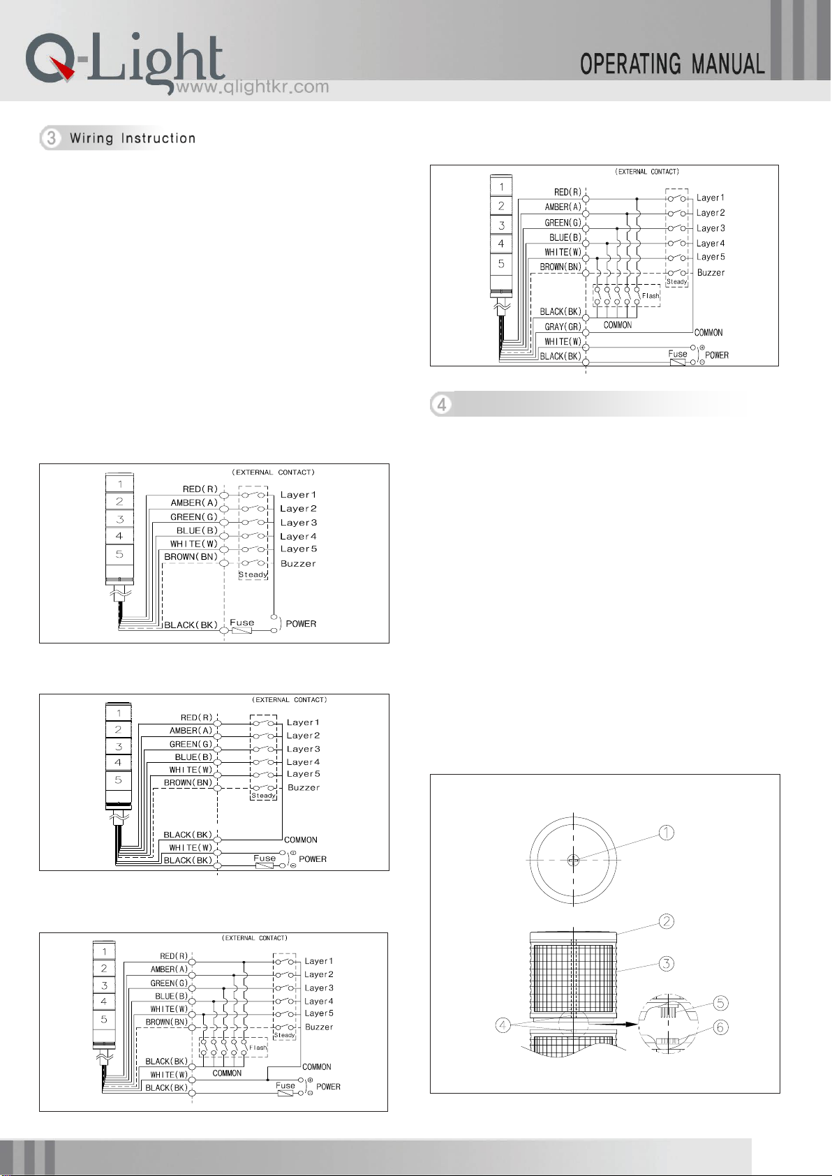
Power and signal lines come out from the product. Please correctly
connect them referring to below instruction.
■DC Steady(Built-in buzzer)
▪Signal line (Power line): UL1007-NO.22(0.3sq) 400mm
▪Steady type can be connected to the power regardless of the
polarity (color)
■DC Steady/Flashing, AC Steady, AC Steady/Flashing(Built-in
buzzer)
▪Power line: UL1015-NO.18(0.75sq)Ⅹ2C 400mm
▪Signal line: UL1007-NO.22(0.3sq) 400mm
▪In case of product using AC voltage, connect the line regardless of the
polarity (color).
▪In case of DC voltage, black line is negative (-).
▸Steady(DC)-ST45(M)L-DC,ST56(M)EL-DC,ST56(M)L-DC,
ST80(M)EL-DC,ST80(M)L-DC
▸Steady(AC)-ST45(M)L-AC,ST56(M)EL-AC,ST56(M)L-AC
ST80(M)EL-AC,ST80(M)L-AC
▸Steady/Flashing(DC)
ST45(M)LF-DC,ST56(M)ELF-DC,ST56(M)LF-DC
ST80(M)EL-DC,ST80(M)LF-DC
▸Steady/Flashing(AC)
ST45(M)LF-AC,ST56(M)ELF-AC,ST56(M)LF-AC
ST80(M)EL-AC,ST80(M)LF-AC
This product is a kit type light and lens. Each kit layer is assembled by
connecting pins. When assembling each kit, please refer to the drawing
and explanation below for right operation
1) Make sure the power is turned off before assembling.
2) Cover Removal
Unscrew the cover bolt①and remove the cover②.
3) Lens Kit Removal
Remove the each lens kit layer by layer by pulling up lens kit③.
4) Lens Kit Change & Assembling
▪When assembling the lens kit, please check the joint part ④and
location of the connecting pin⑤referring to the drawing (two vertical
lines on the surface of the lens)
▪Make sure whether the connecting pin places well on the fitting hole⑥
and gives little push for fixing
▪Make sure whether rubber packing on the top of the lower lens kit is put
inside the upper lens.
5) To assemble the product, please do the reverse orders of
disassembling.