3630 Quick Start Guide Rev. 1-9-15 2
11. Press the green button on the printer, to activate the Emergency Circuit. This button should
illuminate and the “EMERGENCY BUTTON… message should go away.
Tip: If the green button does not illuminate and the “EMERGENCY BUTTON…”
message does not go away, check to be sure all Strapping Plugs are properly
connected, the Emergency Stop Button has been released (reset), the Plexiglas
Cover is closed and the “Finger Guard” is closed.
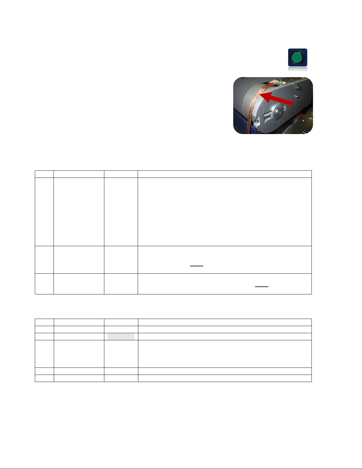
12. The copper “Grounding Straps” are provided to attach
adjacent devices together and reduce the chance for “static
discharge” between devices; which can damage electronics.
Attach these straps to a good earth ground connection on the
conveyor and feeder.
13. Please refer to the User Manual (Operator’s Guide) for
instructions on how to install the printer driver, connecting the
computer, install the ink cartridges and operate the printer.
Identifying Cables and Plugs Included with 3630 System:
NOTE: This cable is not normally needed or used.
This pigtail cable (no connector on one end) can be used to
connect the Emergency Stop “Extern” connection to an
“external device”. The “external device” would need to have
Emergency Stop features that are compatible with the printer.
Pins 1 & 2 Emergency Stop Input (closed = run, open = stop)
Pins 3 & 4 Emergency Stop Output (closed = run, open = stop)
EMERGENCY STOP STRAPPING PLUG OUT
This “dummy plug” has a RED identification mark on it. It must
be installed in any open Emergency Stop “OUT” connection on
EMERGENCY STOP STRAPPING PLUG (dummy plug) IN
This “dummy plug” must be installed in any open Emergency
Stop “IN” connectors on the back of the printer.
Additional Items/Accessories Commonly Needed for 3630 System:
Feeder Stand, Adjustable (FDRSSTAND)
Connects from the “Relay 2” connection on the Printer to the
Feeder (FDR12, FDRSS). Allows the printer to control the
start/stop function of the feeder.


