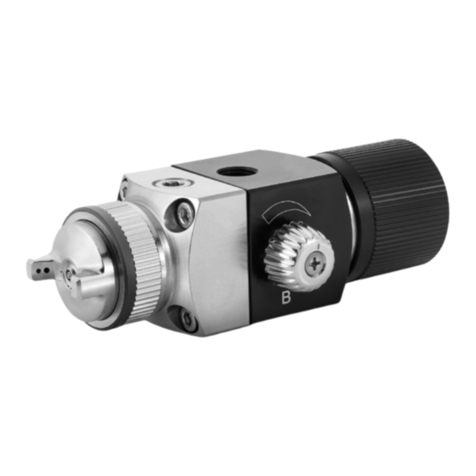
SATA minijet 4400 B User manual

1
EN
Operating instructions SATAminijet 4400 B RP/HVLP Operating instructions SATAminijet 4400 B RP/HVLP
Content [Original Version: German]
1. Symbols.................................... 1
2. Technical Data..........................1
3. Scope of Delivery .....................2
4. Design of the Spray Gun ..........3
5. Intended Use ............................3
6. Safety Instructions....................3
7. Use ...........................................5
8. Cleaning of the Spray Gun .......7
9. Maintenance.............................8
10. Troubleshooting...................... 11
11. Disposal.................................. 13
12. After Sale Service................... 13
13. Warranty / Liability..................13
14. Spare Parts ............................13
15. EC Declaration of
Conformity ..............................15
1. Symbols
Warning! Risk which could cause heavy injuries or death.
Attention! Risk which could cause damage.
Explosion risk! Warning against risk which could cause
heavy injuries or death.
Notice! Useful tips and recommendations.
2. Technical Data
Recommended spray gun inlet pressure
RP 0.5 bar - 2.5 bar
Spot Repair 0.5 bar - 2.5 bar
HVLP 0.5 bar - 2.0 bar
Compliant > 2.0 bar (air cap pressure > 0.7 bar)
Compliant legislation Lom-
bardy/Italy
< 2.5 bar (air cap pressure < 1.0 bar)
Spot Repair 0.5 bar - 2.0 bar
Recommended spraying distance
RP/RP SR 12 cm - 19 cm
HVLP/HVLP SR 12 cm - 15 cm
Max. spray gun inlet pressure
10.0 bar
[EN] Operating Instructions | english
EN-Content-BAL-SATAminijet 4400 B.indd 1 06.05.2014 10:14:31

2
EN
Operating instructions SATAminijet 4400 B RP/HVLP
Air consumption at 2.5 bar spray gun inlet pressure
RP/RP SR 200 Nl/min
Air consumption at 2.0 bar spray gun inlet pressure
HVLP/HVLP SR 120 Nl/min
Max. temperature of the spray medium
50 °C
Weight | Version
without cup 293 g
with 0.3 l RPS cup 325 g
with 0.125 l reusable cup 350 g
with 0.15 l aluminium reusable
cup
393 g
with RPS cup 0.3 l and digital
pressure regulation
367 g
Compressed air connection
G 1/4
Capacity
PVC reusable cup 0,125 l
aluminium reusable cup 0.15 l
RPS cups 0.3 l
3. Scope of Delivery
• Spray gun with nozzle set and
gravity ow cup
• Operating Instructions
• Tool kit
• CCS clips
Alternative versions with:
• Gravity ow cups made of PVC or
aluminium with different capacities
EN-Content-BAL-SATAminijet 4400 B.indd 2 06.05.2014 10:14:31

3
EN
Operating instructions SATAminijet 4400 B RP/HVLP Operating instructions SATAminijet 4400 B RP/HVLP
4. Design of the Spray Gun [1]
[1-1] Spray gun handle
[1-2] Trigger
[1-3] Nozzle set consisting of air
cap, uid tip (not visible),
paint needle (not visible)
[1-4] Spray gun connection with
QCC
[1-5] Gravity ow cup connection
with QCC
[1-6] Paint strainer (not visible)
[1-7] Gravity ow cup
[1-8] Gravity ow cup lid
[1-9] Anti-drip device
[1-10] Round/at spray control
[1-11] Material ow control screw
[1-12] Material ow control counter
nut
[1-13] Air micrometer (air ow
control knob)
[1-14] Air micrometer (air ow con-
trol) locking screw
[1-15] Air piston (not visible)
[1-16] Compressed air connection
[1-17] ColorCode-System (CCS)
5. Intended Use
The spray gun has been designed for the application of paints, lacquers
and other sprayable media by means of compressed air on suitable sub-
strates and surfaces.
6. Safety Instructions
6.1. General safety instructions
Warning! Attention!
• Before using the spray gun, please read all safety and the operating
instructions carefully. Safety instructions and indicated safety meas-
ures are mandatory.
• Please keep all enclosed documents and make sure that the spray
gun is handed over only together with these documents.
6.2. Specific safety instructions for spray guns
Warning! Attention!
• Local safety, accident prevention, work and environment protection
regulations are mandatory!
EN-Content-BAL-SATAminijet 4400 B.indd 3 06.05.2014 10:14:31

4
EN
Operating instructions SATAminijet 4400 B RP/HVLP
Warning! Attention!
• Never direct a spray gun at human beings or animals!
• Use, cleaning and maintenance by skilled personnel only!
• People whose ability to react is impaired by drugs, alcohol, medication
or for other reasons are not allowed to use a spray gun!
• Never use a spray gun when damaged or when components are
missing! Use only when locking screw is rmly tightened [1-14]!
• Before use, the spray gun should always be checked and repaired, if
necessary!
• Put spray gun immediately out of operation when damaged, discon-
nect it from the compressed air circuit!
• Never manipulate or technically modify the paint spray gun!
• Use original SATA spare parts and accessories only!
• Exclusively use spray gun washing machines recommended by SATA!
Please observe the operating instructions!
• Never spray materials containing acid, lye or benzine!
• Alyways keep the spray gun away from ignition sources, such as open
re, burning cigarettes or non-explosion-proof electronic devices!
• When working with the spray gun, always limit solvents, paints or
other coating media to the quantities which are required for the paint
job! Excessive material must be returned to the designated storage
areas afterwards!
6.3. Personal protection equipment
Warning!
• When using, cleaning or maintaining the spray gun, always wear
approved breathing and eye protection equipment as well as suitable
protective gloves, overalls and safety boots!
• When using the spray gun, noise levels of 85 dB(A) may be exceed-
ed. Wear suitable hearing protection!
The painter is not exposed to vibrations while using the spray gun. Repul-
sive forces are minimal.
EN-Content-BAL-SATAminijet 4400 B.indd 4 06.05.2014 10:14:32

5
EN
Operating instructions SATAminijet 4400 B RP/HVLP Operating instructions SATAminijet 4400 B RP/HVLP
6.4. Use in explosive areas
Ex-sign Equipment cat-
egory
Device category Gas category Temperature level
6.4.1 General
The spray gun is approved for the use / storage in explosive areas of Ex-
Zone 1 and 2.
Warning! Risk of explosion!
• The following applications and operations lead to the loss
of the explosion protection and are, therefore, prohibited:
• Use of the spray gun in explosive areas belonging to ex-zone 0!
• Do not use solvents and cleaning agents based on halogenised
hydrocarbons! Chemical reaction which may occur when using these
substances may be explosive!
7. Use
Warning! Risk of explosion!
• Use only solvent-resistant, antistatic, undamaged and technically aw-
less compressed air hoses with a permanent pressure resistance of
minimum 10 bar, e.g. Art. No. 53090!
Note!
The following requirements must be fulfilled:
• Use a compressed air connection G 1/4 a or a tting SATA connection
nipple.
• Ensure minimum compressed air volume (air consumption) and pres-
sure (recommended spray gun inlet pressure) according to chapter 2.
• Use clean compressed air, e.g. by installing the SATA lter 484, Art.
No. 92320
EN-Content-BAL-SATAminijet 4400 B.indd 5 06.05.2014 10:14:32

6
EN
Operating instructions SATAminijet 4400 B RP/HVLP
Note!
• Use an air hose with minimum 9 mm inner diameter (see warnings),
e.g. Art. No. 53090.
1. Check if all screws [2-1], [2-2], [2-3], [2-4] and [2-5] have been tight-
ened rmly. Tighten uid tip [2-1] rmly by hand (12 Nm) according to
[7-4]. Check if locking screw [2-5] has been rmly tightened according
to [10-1]. Tighten, if necessary.
2. Rinse material passages with suitable cleaning solution [2-6], ob-
serve chapter 8.
3. Adjust air cap: vertical spray fan [2-7], horizontal spray fan [2-8].
4. Insert paint strainer [2-9] and install gravity ow cup [2-10].
5. Fill gravity ow cup (max. 20 mm below upper edge), close with the lid
[2-11] and insert anti-drip device [2-12].
6. Screw connection nipple [2-13] (not included in delivery) onto the air
inlet.
7. Connect compressed air hose [2-14].
7.1. Adjust spray gun inlet pressure
Note!
• Pull the trigger fully and adjust the spray gun inlet pressure (see
chapter 2) following instructions of one of the followig sections ([3-1],
[3-2], [3-3] to [3-4]), then release the trigger.
• With [3-2], [3-3] and [3-4], the air micrometer [1-13] has to be fully
opened and in vertical position.
• If the required spray gun inlet pressure is not reached, the pressure
at the compressed air circuit has to be increased; too high pressure
results in too high trigger forces.
[3-1] SATA adam 2 mini (accessory / accurate method).
[3-2] Separate gauge with control device (accessory).
[3-3] Separate gauge without control device (accessory).
[3-4] Pressure regulation at the compressed air circuit (least ac-
curate method): rule of thumb: pressure at the pressure reducer
must be set 0.6 bar higher than the recommended spray gun inlet
pressure per every 10 m of air hose (inner width 9 mm).
EN-Content-BAL-SATAminijet 4400 B.indd 6 06.05.2014 10:14:32

7
EN
Operating instructions SATAminijet 4400 B RP/HVLP Operating instructions SATAminijet 4400 B RP/HVLP
7.2. Adjust material flow [4-1], [4-2], [4-3] und [4-4] - mate-
rial flow control fully opened
Note!
With the material ow control fully opened, the wear of the uid tip and
paint needle is reduced to a minimum. Please select the correct nozzle
size depending on the material to be applied and the required applica-
tion speed.
7.3. Adjust spray fan pattern
• Adjust at fan (factory setting) [5-1].
• Adjust round fan [5-2].
7.4. Painting
Fully pull trigger for painting [6-1]. Operate spray gun according to [6-2].
Maintain spray distance as described in chapter 2.
8. Cleaning of the Spray Gun
Warning! Attention!
• Prior to cleaning, please disconnect the spray gun from the com-
pressed air circuit!
• Risk of injury due to unexpected leakage of compressed air or mate-
rial!
• Empty spray gun and gravity ow cup completely, dispose of paint
material appropriately!
• Disassemble and install components very carefully! Exclusively use
included special tools!
• Use neutral cleaning solution (pH value 6 to 8)!*
• Do not use acids, lyes, bases, pickling agents, unsuitable
regenerates or other aggressive cleaning solutions!*
• Do not soak paint spray gun in cleaning solution!*
• Do not clean cover plate of the electronic pressure display with
pointed, sharp or rough objects!
EN-Content-BAL-SATAminijet 4400 B.indd 7 06.05.2014 10:14:32

8
EN
Operating instructions SATAminijet 4400 B RP/HVLP
Warning! Attention!
• Drillings are to be cleaned with SATA cleaning brushes or SATA nozzle
cleaning needles only. The use of other tools may cause damage or
may affect the spray pattern. Recommended accessory: cleaning kit
Art. No. 64030.
• Exclusively use spray gun washing machines recommended by SATA!
Please observe the operating instructions!
• The air passages have to be pressurised with clean compressed air dur-
ing the entire cleaning process!
• Nozzle head has to point downwards!
• Remove the spray gun from the gun washing machine right
after the cleaning process!*
• Never use ultrasonic cleaning devices - leads to damage of noz-
zle set and gun surface!
• After cleaning, the spray gun, the material passages, the air
cap including thread as well as the gravity flow cup have to
be blown dry with clean compressed air!*
* otherwise risk of corrosion
Note!
• Check spray pattern after cleaning the nozzle set!
• Further tips concerning cleaning can be found at www.sata.com/TV.
9. Maintenance
Warning! Attention!
• Prior to maintenance, disconnect the spray gun from the compressed
air circuit!
• Disassemble and install components very carefully! Exclusively use
included special tools!
EN-Content-BAL-SATAminijet 4400 B.indd 8 06.05.2014 10:14:32

9
EN
Operating instructions SATAminijet 4400 B RP/HVLP Operating instructions SATAminijet 4400 B RP/HVLP
9.1. Replacing the nozzle set [7-1], [7-2], [7-3], [7-4], [7-5]
and [7-6]
Every SATA nozzle set consists of "paint needle" [7-1], "air cap" [7-2]
and "uid tip" [7-3] and has been hand-adjusted to provide a perfect
spray pattern. Therefore, always exchange the complete nozzle set. After
installation, please adjust material ow according to chapter 7.2.
9.2. Replacing the air distribution ring
Steps: [7-1], [7-
2], [7-3], [8-1], [8-2] [8-3], [7-4], [7-5] und [7-6]
Attention!
• Remove air distribution ring with SATA extraction tool only.
• Do not apply force to avoid damage of sealing surfaces.
Note!
Check sealing surfaces inside the spray gun [8-2] after disassembly,
clean them, if required. Should the sealing surfaces be damaged,
please contact your SATA dealer. Align new air distribution ring with the
help of the marking [8-3], (pin must be located in the drilling) and press
in with even force. Adjust material ow according to chapter 7.2 after
installation.
9.3. Replacing the paint needle sealing Steps: [9-1],
[9-2] and [9-3]
When paint material leaks from the self-tensioning paint needle packing, it
needs to be replaced. Remove trigger according to [9.2]. After disassem-
bly, check if paint needle is damaged or replace the nozzle set, if required.
Adjust material ow according to chapter 7.2 after installation.
9.4. Replacing the air piston, air piston spring and
air micrometer Steps: [10-1], [10-2] and [10-3]
Warning!
• Disconnect the spray gun from the compressed air circuit!
When air leaks from the air cap or the air micrometer without the trigger
being pulled, they need to be replaced. After disassembly, grease the air
EN-Content-BAL-SATAminijet 4400 B.indd 9 06.05.2014 10:14:32

10
EN
Operating instructions SATAminijet 4400 B RP/HVLP
micrometer and spring with SATA high performance grease (Art. No.
48173), insert them together with the air piston and thighten the locking
screw [10-1]. Adjust material ow according to chapter 7.2 after installa-
tion.
Warning!
• Check if locking screw has been rmly tightened! Air micrometer could
shoot out from the spray gun uncontrolled!
9.5. Replacing the sealing (air side)
Warning!
• Disconnect paint spray gun from the compressed air circuit!
Steps: [9-1], [9-2], [10-1], [10-2], [10-3], [10-4], [10-5] and [10-6]
Replacing the self-adjusting sealing [10-6] is required when air leaks
from under the trigger.
1. After disassembly, please check air piston rod [10-4] and clean it, if
required. If damaged (e.g. if scratched or bent), replace it and grease
with SATA high performance spray gun grease (Art. No. 48173) and
insert. Please observe correct order of installation!
2. Lubricate air micrometer (air ow control) and spring as well, insert
together with air piston and tighten the locking screw.
After installation, please adjust material ow according to chapter 7.2.
Warning!
• Check if locking screw has been rmly tightened! Air micrometer could
shoot out from the spray gun uncontrolled!
9.6. Replace spindle of round/flat spray control
steps: [11-1], [11-2], [11-3]
The spindle has to be replaced when air leaks from the spray control or
when the spray control does not work.
EN-Content-BAL-SATAminijet 4400 B.indd 10 06.05.2014 10:14:32

11
EN
Operating instructions SATAminijet 4400 B RP/HVLP Operating instructions SATAminijet 4400 B RP/HVLP
10. Troubleshooting
Malfunction Cause Corrective Action
Fluttering/spitting
spray fan or air bub-
bles appearing in the
gravity ow cup
Fluid tip has not been
properly tightened
Tighten uid tip [2-1]
with universal spanner
Air distribution ring is
damaged or clogged.
Replace air distribu-
tion ring, as it will be
damaged during disas-
sembly
Air bubbles appearing
in the gravity ow cup
Loose air cap Tighten air cap [2-2]
by hand
Gap between air cap
and uid tip ("air cir-
cuit") is clogged
Clean air circuit, ob-
serve chapter 8
Nozzle set is clogged
or damaged
Clean nozzle set,
chapter 8, or replace,
respectively, chapter
9.1
Not enough paint ma-
terial in the gravity ow
cup
Rell gravity ow cup
[1-6]
Defective paint needle
sealing
Replace the paint nee-
dle sealing, chapter
9.3
Spray pattern is too
small, crooked, lop-
sided or splitting
Clogged air cap drill-
ings
Clean air cap, observe
chapter 8
Damaged uid tip (uid
tip aperture)
Check if uid tip is
damaged, replace the
nozzle set, if neces-
sary, chapter 9.1
No function of round/
at spray control - con-
trol knob can still be
turned
Air distribution ring has
not been positioned in
correct location (pin is
not located in the drill-
ing) or damaged
Replace air distribution
ring making sure it has
been positioned cor-
rectly when inserting it,
chapter 9.2
EN-Content-BAL-SATAminijet 4400 B.indd 11 06.05.2014 10:14:32

12
EN
Operating instructions SATAminijet 4400 B RP/HVLP
Malfunction Cause Corrective Action
Round/at spray con-
trol cannot be regu-
lated
Regulation valve dirty Remove round/at
spray control, repair or
replace it, chapter 9.7
Spray gun does not
shut-off air
Clogged air piston seat
or worn air piston.
Clean air piston seat
and/or replace air pis-
ton, air piston packing,
chapter 9.4
Corrosion on air cap
thread, inside material
passages (cup con-
nection) or on spray
gun body
Cleaning solution
(water-based) remains
inside/on the spray
gun for too long.
Cleaning, observe
chapter 8, get a
replacement spray
gun body.
Unsuitable cleaning
solutions
Black digital display Spray gun has been
soaked in cleaning
solution for too long
Cleaning, observe
chapter 8, get a re-
placement digital unit
Wrong positioning of
the spray gun inside
the gun washing ma-
chine
Material leaks from
behind the paint nee-
dle sealing.
Defective or missing
paint needle sealing.
Replace / insert paint
needle sealing, chap-
ter 9.3.
Clogged or damaged
paint needle.
Replace nozzle set,
chapter 9.1; replace
paint needle sealing,
if necessary, chapter
9.3.
Spray gun leaks from
the uid tip ("uid tip
aperture").
Contamination be-
tween paint needle tip
and uid tip.
Clean uid tip and
paint needle, observe
chapter 8.
Damaged nozzle set. Replace nozzle set,
chapter 9.
EN-Content-BAL-SATAminijet 4400 B.indd 12 06.05.2014 10:14:33

13
EN
Operating instructions SATAminijet 4400 B RP/HVLP Operating instructions SATAminijet 4400 B RP/HVLP
11. Disposal
Recycle the completely empty spray gun. To protect the environment, bat-
teries and residual paint have to be disposed in an appropriate way and
separately from the spray gun. Please observe local legislation!
12. After Sale Service
Please refer to your local SATA dealer for accessories, spare parts and
technical support.
13. Warranty / Liability
The SATA General Conditions of Sale and Delivery and further contractual
agreements, if applicable, as well as the valid legislation at the time apply.
SATA cannot be held liable especially in the following cases:
• When the operating instructions are disregarded.
• When the product is used in other than the intended ways of use.
• When untrained staff is employed.
• When no personal protection equipment is worn.
• When no original accessories and spare parts are used.
• When the product is manipulated, tampered with or technically modi-
ed.
• In case of normal wear and tear.
• In case when the product has been exposed to untypical shockloads
and impacts during usage.
• Assembly and disassembly
14. Spare Parts [13]
Art.
No. Description
3988 Single pack of 10 paint strainers
16295 25 ml Glass cup with plug-in lid
53033 25 ml glass cup with blind lid (5x)
58164 25 ml glass cup with plug-in lid (5x)
64022 PVC lid (3x)
76018 Pack of 10 x 10 paint strainers
76026 Pack of 50 x 10 paint strainers
EN-Content-BAL-SATAminijet 4400 B.indd 13 06.05.2014 10:14:33

14
EN
Operating instructions SATAminijet 4400 B RP/HVLP
Art.
No. Description
133983 Air connection piece G 1/4 - G 1/4
197418 Pack of 4 CCS clips (green, blue, red, black)
197467 Pack of 3 air distribution rings
197541 0.125 l QCC quick change gravity ow cup (PVC)
197558 Pack of 4 anti-drip devices for 0.125 l PVC cup
198408 Air piston rod
198473 Trigger kit
198523 Air micrometer (air ow control knob)
198549 Spindle for round/at spray control
198572 Tool kit
198911 0.15 l QCC aluminium reusable cup
199075 Screw-on lid for 0.125 l PVC cup
199406 Material ow control with counter nut
199414 Paint needle sealing and air piston rod sealing
199430 Pack of 3 locking screws for air micrometer
199448 Pack of 3 air piston heads
199455 Pack of 5 sealing elements for uid tip
199463 Trigger sleeve kit
199471 Pack of 3 sealings for spindle round/at spray control
201467 Spring set consisting of 3x paint needle springs and 3x air
piston springs each
200162 Control knob and screw (2 pieces each)
200220 Plug-in cup connection
200238 25 ml glass cup with plug-in lid (5x) and QCC plug-in connec-
tion (1x)
200907 Sealing ring for air cap (5x)
Included in repair kit (Art No. 198614)
Included in air piston service unit (Art. No. 199422)
Included in sealing kit (Art. No. 200246)
EN-Content-BAL-SATAminijet 4400 B.indd 14 06.05.2014 10:14:33

15
EN
Operating instructions SATAminijet 4400 B RP/HVLP Operating instructions SATAminijet 4400 B RP/HVLP
15. EC Declaration of Conformity
Manufacturer:
SATA GmbH & Co. KG
Domertalstrasse 20
D-70806 Kornwestheim
We hereby declare that the following product in the version sold by SATA,
due to its conception, design and construction complies with the basic
safety requirements of the directive 94/9/EU including the modications
valid at the time of the declaration, and that it can be used in explosive
areas (ATEX), annex X, B, according to EU directive 94/9/EU.
Product description: ......................................... paint spray gun
Type description: .........................SATAminijet 4400 B RP/HVLP
ATEX classification: .................................................... II 2 G T4
Relevant EC directives:
• EN 60079-0:2013, EN 60079-11:2012, EN 60079-26:2007
• EC directive 94/9/EC Geräte und Schutzsysteme zur bestim-
mungsgemäßen Verwendung in explosionsgefährdeten Bereichen (De-
vices and protection systems for the intended use in explosive areas).
• EU machinery directive 98/37/EU (until December 28, 2009)
• EU machinery directive 2006/42/EG
Applied harmonised norms:
• DIN EN 1127-1:2011 "Explosion control part 1: Basics and methodol-
ogy"
• DIN EN 13463-1:2009 "Non-electronic devices for the use in explosive
areas - Part 1: Basics and Requirements"
• DIN EN ISO 12100:2011; "Machine safety, general requirements"
• DIN EN 1953:2013 "Spray and application devices for coating materials
- safety requirements"
Applied national norms:
• DIN 31000:2011 "General guidelines for the safety-compliant design of
technical products"
The respective documents required by directive 94/9/EU Annex VIII are
deposited for 10 years at the designated location, number 0123 with the
documentation number 70023722.
EN-Content-BAL-SATAminijet 4400 B.indd 15 06.05.2014 10:14:33

16
EN
Operating instructions SATAminijet 4400 B RP/HVLP
70806 Kornwestheim, March 27, 2014
Albrecht Kruse
President
SATA GmbH & Co. KG
EN-Content-BAL-SATAminijet 4400 B.indd 16 06.05.2014 10:14:33
Table of contents
Other SATA Paint Sprayer manuals

SATA
SATA jet H User manual

SATA
SATA SATAgraph 1 User manual

SATA
SATA SATAjet 3000 A HVLP User manual

SATA
SATA H NR 95 User manual

SATA
SATA SATAjet 1000 ROB RP User manual

SATA
SATA spray master RP User manual

SATA
SATA SATAjet X 5500 User manual

SATA
SATA SATAjet B User manual

SATA
SATA SATAjet 3000 B RP User manual

SATA
SATA SATAjet 1000 K HVLP User manual
SATA
SATA top air User manual

SATA
SATA multi clean 2 User manual

SATA
SATA Jet 4000 B User manual

SATA
SATA SATAjet 1000 A RP User manual

SATA
SATA SATAjet 2000 LAB HVLP User manual

SATA
SATA SATAjet 4000 B User manual
SATA
SATA sataminijet 4400 B User manual

SATA
SATA SATAjet 4600 B User manual

SATA
SATA Paint set 10 User manual
SATA
SATA SATAjet 1000 K HVLP User manual