manuals.online logo
Brands
  1. Home
  2. •
  3. Brands
  4. •
  5. SIP
  6. •
  7. Farm Equipment
  8. •
  9. SIP STAR 600/20 T User manual

SIP STAR 600/20 T User manual

Other manuals for STAR 600/20 T

1

Other SIP Farm Equipment manuals

SIP SPIDER 615/6 User manual

SIP

SIP SPIDER 615/6 User manual

SIP SPIDER 615 PRO User manual

SIP

SIP SPIDER 615 PRO User manual

SIP STAR 430/12V User manual

SIP

SIP STAR 430/12V User manual

SIP SPIDER 230/2 ALP User manual

SIP

SIP SPIDER 230/2 ALP User manual

SIP STAR 300/8 ALP User manual

SIP

SIP STAR 300/8 ALP User manual

SIP Roto 251 S User manual

SIP

SIP Roto 251 S User manual

SIP STAR 360/10 User manual

SIP

SIP STAR 360/10 User manual

SIP FAVORIT 224 User manual

SIP

SIP FAVORIT 224 User manual

SIP STAR 360/10 User manual

SIP

SIP STAR 360/10 User manual

SIP SPIDER 815 Z PRO User manual

SIP

SIP SPIDER 815 Z PRO User manual

SIP SPIDER 815/8 User manual

SIP

SIP SPIDER 815/8 User manual

SIP OPTICUT DISC 220 F ALP User manual

SIP

SIP OPTICUT DISC 220 F ALP User manual

SIP SPIDER 1100/10T User manual

SIP

SIP SPIDER 1100/10T User manual

SIP FAVORIT 234 F ALP User manual

SIP

SIP FAVORIT 234 F ALP User manual

SIP STAR 471 User manual

SIP

SIP STAR 471 User manual

SIP STAR 600/20 T User manual

SIP

SIP STAR 600/20 T User manual

SIP STAR 430/12 T User manual

SIP

SIP STAR 430/12 T User manual

SIP SILVERCUT DISC 800 C RC User manual

SIP

SIP SILVERCUT DISC 800 C RC User manual

SIP SPIDER 400/4 User manual

SIP

SIP SPIDER 400/4 User manual

SIP SPIDER 455/4 User manual

SIP

SIP SPIDER 455/4 User manual

SIP STAR 850/26 User manual

SIP

SIP STAR 850/26 User manual

SIP STAR 350/8 ALP User manual

SIP

SIP STAR 350/8 ALP User manual

SIP SILVERCUT DISC 1500 T User manual

SIP

SIP SILVERCUT DISC 1500 T User manual

SIP STAR 700/22 T User manual

SIP

SIP STAR 700/22 T User manual

Popular Farm Equipment manuals by other brands

Schaffert Rebounder Mounting instructions

Schaffert

Schaffert Rebounder Mounting instructions

Stocks AG Fan Jet Pro Plus 65 Original Operating Manual and parts list

Stocks AG

Stocks AG Fan Jet Pro Plus 65 Original Operating Manual and parts list

Cumberland Integra Feed-Link Installation and operation manual

Cumberland

Cumberland Integra Feed-Link Installation and operation manual

BROWN BDHP-1250 Owner's/operator's manual

BROWN

BROWN BDHP-1250 Owner's/operator's manual

Molon BCS operating instructions

Molon

Molon BCS operating instructions

Vaderstad Rapid Series instructions

Vaderstad

Vaderstad Rapid Series instructions

HighLine BM1400 operating manual

HighLine

HighLine BM1400 operating manual

GSi PNEG-2314 installation manual

GSi

GSi PNEG-2314 installation manual

Checchi & Magli TEXDRIVE owner's manual

Checchi & Magli

Checchi & Magli TEXDRIVE owner's manual

Amazone Cenius 4003-2TX operating manual

Amazone

Amazone Cenius 4003-2TX operating manual

MASSEY FERGUSON MF 9313S Operator's manual

MASSEY FERGUSON

MASSEY FERGUSON MF 9313S Operator's manual

Cima BLITZ Maintenance Instruction

Cima

Cima BLITZ Maintenance Instruction

Amazone CombiDisc 3000 Original operating manual

Amazone

Amazone CombiDisc 3000 Original operating manual

HE-VA Disc-Roller XL Contour Operating instructions/spare parts list

HE-VA

HE-VA Disc-Roller XL Contour Operating instructions/spare parts list

AGT AGT-SSFM product manual

AGT

AGT AGT-SSFM product manual

Milestone 72-84 manual

Milestone

Milestone 72-84 manual

KUHN Hector 3000 Complementary instructions

KUHN

KUHN Hector 3000 Complementary instructions

Krone X-Disc 6200 operating instructions

Krone

Krone X-Disc 6200 operating instructions

manuals.online logo
manuals.online logoBrands
  • About & Mission
  • Contact us
  • Privacy Policy
  • Terms and Conditions

Copyright 2025 Manuals.Online. All Rights Reserved.

vrtavkasti zgrabljalnik
rotacioni sakupljač
kreiselschwader
kreiselheuer
kreiselschwader
andaineuse rotative
zwadmaaier
Rotorsträngläggare
SLO
Navodilo za sestavo
HR
Uputstva za montažu
GB
Mounting instructions
D
Zusammenbauanleitung
I
Istruzioni di montaggio
F
Instructions de montage
NL
Montagevoorschriften
Monteringsinstruktioner
STAR 600/20 T
Spoštovani kupec!
V tem navodilu je prikazana sestava dvorotorskega vrtavkastega zgrabljalnika STAR 600/20 T iz
transportnega zaboja do stroja , ki je pripravljen za delo. Nasvet: pri montaži lahko uporabite tudi
slike iz
»Navodila za uporabo«. Za normalno delo priporočamo strokovno usposobljene osebe, običajno orodje
in uporabo dvigalne naprave (npr. škripec, viličar...). Ves ostali droben material je spravljen v tulcu. Vse
dimenzije vijakov in ostalih elementov v tem navodilu so podane v milimetrih (mm). Pred začetkom
sestave, z zaboja odstranite PVC folijo in pokrov. Iz zaboja odstranite vse manjše elemente, ter
odstranite stranice.
Za dvig večjih elementov iz zaboja priporočamo uporabo dvigalne naprave, ki pa mo
ra imeti zadosti
veliko nosilnost. Okrog večjih elementov ovijte dvigalni jermen z nosilnostjo najmanj 5 kN (približno 500
kg) - pod dvigalni jermen podložite trak folije - tako, da preprečite odrgnjenje barve. Elemente postavite
na primerno trdno in čisto podlago. Upoštevajte navodila za varno delo!
Poštovani kupac!
U ovim uputstvima je naveden postupak sastavljanja dvorotorskog rotacionog sakupljača STAR
600/20 T od otvaranja sanduka do sastavljenog sakupljača, pripremljenog za rad. Savet za montažu:
možete upotrebiti slike iz »Uputstava za upotrebu«. Za pravilno i sigurno sastavljanje preporučujemo da
stručna osoba koristi dizalicu ili viljuškar i uobičajeni alat. Potrebni elementi za montažu sklopova su u
kutiji. Sve dimenzija vijaka i drugih elemenata su napisane u milimetrima (mm).
Pred montažom
odstranite PVC foliju i pokrov sanduka. Iz sanduka izvadite sve manje elemente i odstranite stranice
sanduka.
Za dizanje težih elemenata iz sanduka preporučujemo upotrebu dizalice, koja mora imati
zadovoljavajuću nosivost. Veće elemente zaštitite sa folijom, vežite ih sa remnikom, koji ima nosivost
najmanje 5 kN (približno 500 kg). Elemente postavite na tvrda tla, vodite računa o sigurnosti i
povredama.
Sehr geehrter Käufer!
In dieser Anleitung ist das Zusammenbau des Zwei-Rotor Kreiselschwaders STAR 600/20 T
beschrieben, von der Transportkiste bis zur Maschine im Einsatzbereit. Hinweis: Bei dem Zusammenbau
können auch die Zeichnungen aus der "Betriebsanleitung“ besichtigt werden. Für Normalarbeit sind
fac
hbefähigte Personen, übliches Werkzeug und Hubeinrichtungen (Seilaufzug, Gabelstapler, ...)
empfohlen. Sämtliche Kleinelemente befinden sich im Kunststoffrohr beigepackt. Alle Schrauben- und
Elementdimensionen in dieser Anleitung sind in Milimeter (mm) gegeben.Vor dem Zusammenbaubeginn,
die Kunststofffolie und den Deckel von Kiste entfernen. Alle Kleinelemente aus der Kiste nehmen und die
Seite beseitigen.
Zum Aufheben größeren Elemente ist eine Hubeinrichtung mit genügender Tragfähigkeit empfohlen. Um
größeren Elemente den Heberiemen mit mindestens 5 kN (etwa 500 kg) Tragfähigkeit wickeln - Folie
unter den Heberiemen stellen - um Farbenschädigung zu vermeiden. Alle Bestandteile auf feste und
saubere Unterlage stellen. Die Sicherheitshinweise berücksichtigen!
Dear Buyer!
This instruction shows how to mount the two rotor windrower STAR 600/20 T
, from the crate to the
machine prepared for work. Advice: Take a look at the pictures in “Instructions for work”. For normal work
technically qualified persons, usual tool and lifting device (pulley, forklift, ...) are recommanded. Small
assembling parts are to be found in the plastic tube.The dimensions of screws and other elements are
shown in milimeters (mm). Remove the plastic foil and the cover from the crate be
fore starting the
construction. Take all smal elements from the crate and remove the sides.
For lifting the bigger elements from the crate a lifting device with sufficient load capacity is
recommanded. Wind the belt with at least 5 kN (approx. 500 kg) load capacity round big elements – put
the PVC foil under the lifting belt – to prevent the colour damage. Place the elements on solid and clean
ground. Consider the instructions for safe work!
1
Caro acquirente!
Queste istruzioni mostrano come montare il ranghinatore a due rotori STAR 600/20 T, dalla cassa alla
macchina preparata per il lavoro. Avviso: Dare un'occhiata alle figure in “Istruzioni di lavoro”. Per un
lavoro normale, si raccomandano persone tecnicamente qualificate, attrezzi usuali e dispositiv
i di
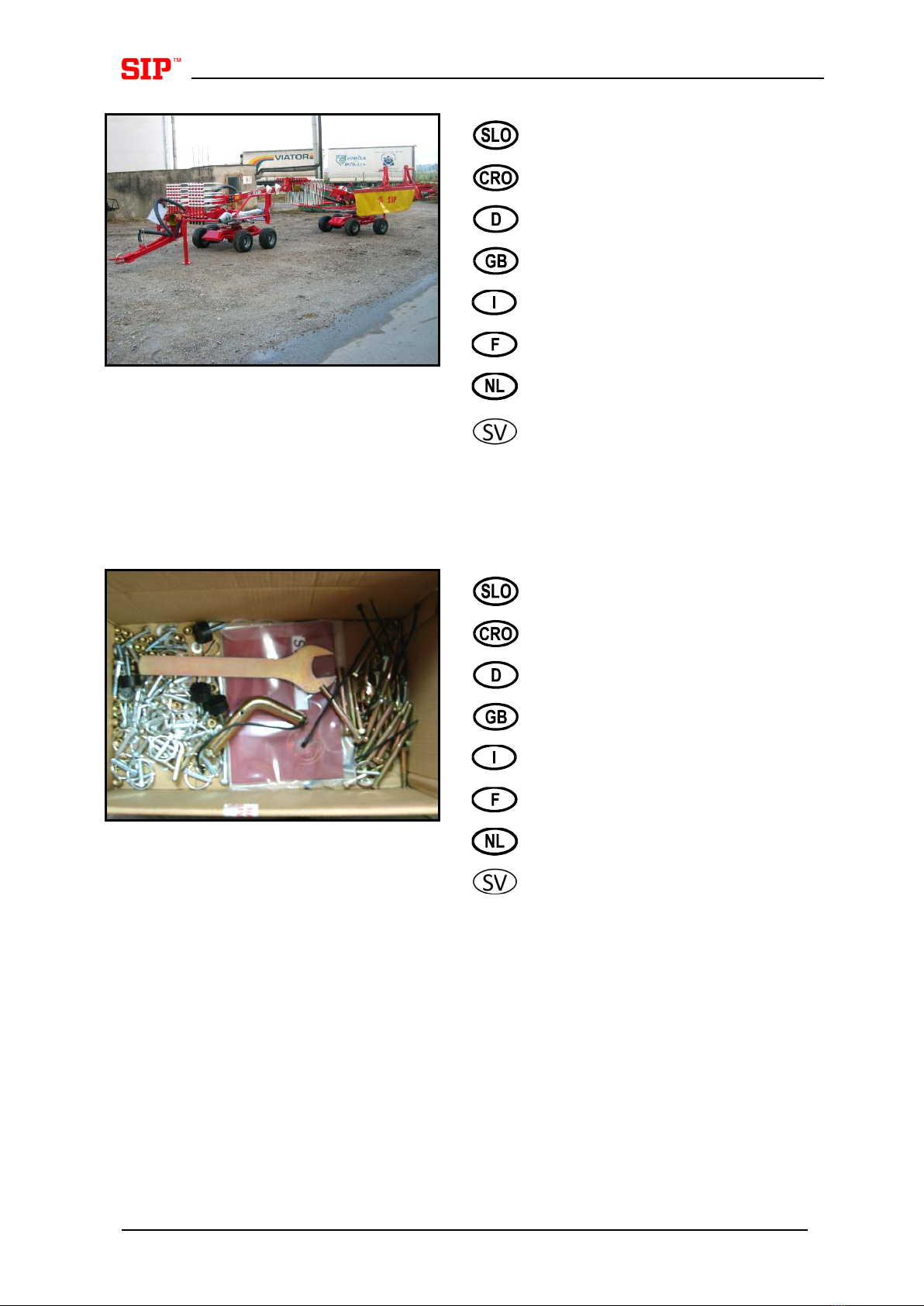
sollevamento (puleggia, carrelli elevatori). I pezzi di assemblaggio più piccoli si trovano nel tubo di
plastica. Le dimensioni delle viti e gli altri elementi sono mostrati in millimetri (mm). Rimuovere il foglio di
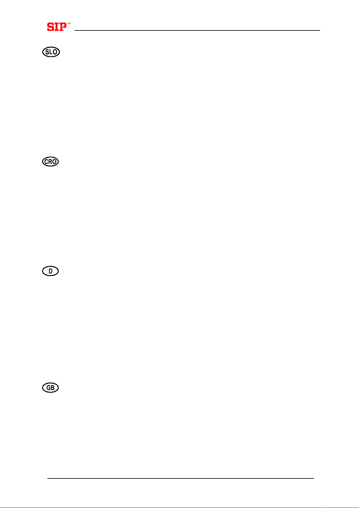
plastica e il coperchio dalla cassa prima di eseguire la costruzione. Prendere tutti gli elementi più piccoli
dalla cassa e rimuovere i lati.
Per il sollevamento degli elementi più grandi dalla cassa, si raccomanda un dispositivo di sollevamento
con capacità di carico sufficiente. Avvolgere la cinghia con una capacità di carico di almeno 5 kN (circa
500 kg) intorno agli elementi più elementi – mettere il foglio PVC sotto la cinghia di sollevamento – per
prevenire il danneggiamento del colore. Posizionare gli elementi su un terreno solido e
pulito. Prendere
in considerazione le istruzioni per lavoro sicuro!
Cher client,
Ces instructions vont vous guider lors du montage de l'andaineuse à double rotor STAR 600/20 T
, de
la caisse d'emballage à la machine prête à l'emploi. Recommandations :
Regardez les illustrations
incluses dans le « Mode d'emploi ». Pour un travail normal, il est recommandé que les personnes soient
qualifiées et qu'elles utilisent les outils et appareils de levage (poulie, chariot élévateur à fourche,...)
habituels. Les petites parties d'assemblage se trouvent dans le tuyau en plastique. Les dimensions des
vis et autres éléments sont indiquées en millimètres (mm). Retirez le film plastique et le couvercle de la
caisse d'emballage avant de commencer l'assemblage. Retirez tou
s les petits éléments de la caisse
d'emballage et enlevez les parois.
Pour retirer les gros éléments de la caisse d'emballage, un appareil de levage avec une capacité de
charge suffisante est recommandé. Enroulez la ceinture autour des gros éléments ronds d'au moins 5 kN
(environ 500 kg) de capacité de charge – placez le fim plastique sous la ceinture de levage – pour éviter
d'endommager la peinture. Placez les éléments sur un sol dur et propre. Respectez les consignes de
sécurité !
Beste koper!
Deze instructie toont u hoe u de dubbele rotor zwadmaaier START 600/20 T
, vanaf de verpakking tot
een gebruiksklare machine, moet monteren. Advies: Kijk naar de foto's in de “Werkinstructies”. Voor
normaal werk zijn technisch gekwalificeerde personen, normaal ge
reeschap en heftoestellen (katrol,
vorklift, ...) aangewezen. Kleine montageonderdelen kunnen in de kunststof buis worden gevonden. De
afmetingen van de schroeven en andere elementen worden in millimeter (mm) gegeven.
Verwijder de
plastiek folie en het deksel van de verpakking voor u met de montage begint.
Neem alle kleine
onderdelen uit de verpakking en verwijder de zijkanten.
Voor het optillen van de grotere onderdelen uit de verpakking is een heftoestel met voldoende
laadcapaciteit aangewezen. Wind de riem met tenminste 5 kN (ongeveer 500 kg) laadcapaciteit rond
grote onderdelen – plaats de PVC – folie onder de ophefriem – om kleurschade te voorkomen. Plaats de
onderdelen op een vaste en schone ondergrond. Neem de instructies voor veilig werk in acht!
Bästa kund!
Denna instruktion visar hur delarna i lådan sätts samman till en
rotorsträngläggare med två rotorer
STAR 600/20 T, färdig för arbete. Tips: t
a en titt på bilderna i ”Instruktionsboken”. För arbetet
rekommenderas personer kvalificerade för normalt tekniskt arbete, normala verktyg och lyftdon (lyftblock,
gaffeltruck, ...). Små monteringsdetaljer finner du i plaströret. Dimensioner på skruvar och övriga element
anges i millimeter (mm). Ta bort plastfolien och locket från lådan innan du börjar med hopmonteringen.
Plocka bort alla mindre detaljer ur lådan och ta sedan bort sidorna.
För att lyfta bort de större delarna ur lådan rekommenderas en lyftanordning med tillräcklig lyftkapacitet.
Linda lyftstroppen med minst 5 kN (ca 500 kg) lyftkapacitet runt de större delarna. Lägg plastfolien under
lyftstroppen för att förhindra lackskador. Lägg ner delarna på fast och rent underlag. Beakta
instruktionerna som berör säkert arbete!
2
Sestavljen stroj.
Sastavljen stroj.
Zusammengebaute Maschine.
Mounted machine.
Macchina montata.
Machine assemblée.
Machine.
Hopmonterad maskin.
Vsebina tulke.
Sadržaj kutije.
Hülseinhalt.
Contents of the case.
Contenuto della cassa.
Contenu de la caisse.
Inhoud van de verpakking.
Kartongens innehåll.
3
Pred montažo jarema kpl. postavite
s
prednje in zadnje podvozje nekaj
metrov narazen (kot kaže slika).
Prije montaže jarma kpl. nekoliko
metara razmaknite prednje i zadnje
podvozje (kao što prikazuje slika).
Vor der Jochmontage zus. das
Vorder-
und Hinterfahrwerk einige
Meter ause
inandersetzen (wie auf
dem Bild gezeigt).
Before mounting the yoke cpl. set the
front and rear chassis a few meters
apart (as shown in the picture).
Prima del montaggio del giogo cpl.,
impostare il telaio anteriore e
posteriore a pochi metri di distanza
(come mostrato nella foto).
Avant d'assembler l'ens. de la chape
d'attelage placez les châssis avant et
arrière à quelques mètres l'un de
l'autre (comme indiqué sur
l'illustration).
Voor u het juk kpl. monteert, zet u het
voorste en a
chterste chassis enkele
meters appart (zoals getoond in de
afbeelding).
Innan du monterar det kompletta oket,
ska främre och bakre chassit placeras
några meter isär (som visas i bilden).
Jarem privijte z sedmini vijaki M12x40,
maticami
M12 in podložkami SKM 12
(poz. A).
Jaram pričvrstite sa sedam vijaka
M12x40 i podloškama SKM 12 (poz.
A).
Das Joch mit sieben Schrauben
M12x40, Muttern M12 und Scheiben
SKM 12 (Pos. A) festziehen.
Screw the yoke with seven screws
M12x40, nuts M12 and washers SKM
12 (pos. A).
Fissare il giogo con sette viti M12x40,
dadi M12 e rondelle SKM 12 (pos. A).
Vissez la chape d'attelage avec sept
vis M12x40, des écrous M12 et des
rondelles SKM 12 (pos. A).
A
4
Schroef de juk met zeven schroeven
M12x40, moeren M12 en sluitringen
SKM 12 (pos. A) vast.
Skruva fast oket med sju skruvar
M12x40, muttrar M12 och brickor
SKM 12 (pos. A).
Na zadnjem podvozju kpl. privijte
jarem z ohišjem kpl. (poz. B), osmimi
vijaki M12x25
in podložkami SKM 12
(poz. C).
Na zadnjem podvozju kpl. pričvrstite
jaram s kućištem kpl. (poz. B), s osam
vijaka M12x25 i podloškama SKM 12
(poz. C).
Das Joch mit Gehäuse zus. auf
Hinterfahrwerk (Pos. B), acht
Schrauben M12x25 und Scheiben
SKM12 (Pos. C) festziehen.
Screw the yoke with housing cpl. on
the rear chassis with eight screws
M12x25 and washers SKM12
(pos. C).
Fissare il giogo con alloggiamento cpl.
(pos. B) sul telaio posteriore con otto
viti M12x25 e rondelle SKM12
(pos. C).
Vissez la chape d'attelage avec l'ens.
tulipe (pos. B) sur le châssis arrière
avec huit vis M12x25 et des rondelles
SKM12 (pos. C).
Schroef de juk met de behuizing kpl.
(pos. B) op het achterste chassis met
acht schroeven M12x25 en sluitringen
SKM12 (pos. C).
Skruva fast oket med det kompletta
huset på bakre chassit med åtta
skruvar M12x25 och brickor SKM12
(pos. C).
B
C
5
Na sprednjem podvozju kpl. privijte
jarem s štirimi vijaki M16x35 in
podložkami SKM 16 (poz. C).
Na prednjem podvozju kpl. pričvrstite
jaram s četiri vijaka M16x35 i
podloškama SKM 16 (poz. C).
Auf Vorderfahrwerk das Joch mit vier
Schrauben M16x35 und Scheiben
SKM16 (Pos. C) festziehen.
Screw the yoke on the front chassis
with four screws M16x35 and washers
SKM16 (pos. C).
Fissare il giogo sul telaio anteriore con
quattro viti M16x35 e rondelle SKM16
(pos. C).
Vissez la chape d'attelage sur le
châssis avant avec quatre vis M16x35
et des rondelles SKM16 (pos. C).
Schroef de juk op het voorste chassis
met vier schroeven M16x35 en
sluitringen SKM16 (pos. C).
Skruva fast oket på främre chassit
med fyra skruvar M16x35 och brickor
SKM (pos. C).
C
6
Vstavite podporno nogo (poz. A) in jo
zavarujte z zatikom 8x60 in zatikom z
vzmetjo (poz. B). Enako storite tudi na
drugi strani (poz. C).
Namestite potpornu nogu (poz. A),
osigurajte je sa zatikom s oprugom
(poz. B). Jednako uradite
i s druge
strane (poz. C).
Den Stützfuss einsetzen (Pos. A) und
mit Splint 8x60 und Federsplint (Pos.
B) sichern. Das Gleiche auf anderer
Seite tun (Pos. C).
Insert the support leg (pos. A) and
secure it with clip 8x60 and spring clip
(pos. B)
. Do the same on the other
side (pos. C).
Inserire la gamba di supporto (pos. A)
e assicurarla con un gancio 8x60 e
una molla (pos.
B). Fare lo stesso
sull’altro lato (pos. C).
Insérez la béquille (pos. A) et fixez–la
avec l'attache 8x60 et l'attache ressort
(pos. B). Faites la même chose de
l'autre côté (pos. C).
Breng het steunbeen in (pos.
A) en
maak vast met clip 8x60 en veerclip
(pos. B). Doe hetzelfde aan de andere
kant (pos. C).
Skjut in stödbenet (pos. A) och säkra
det med en
sprint 8x60 och ringsprint
(pos. B). Gör samma sak på andra
sidan (pos. C).
A
B
C
7
Montirajte priklop na stroj (poz. A).
Vstavite hidravlični cilinder (poz. B)
sornik (poz. C) in zavarujte na vsaki
strani z zatikom 8x60 in podložko.
Vstavite v
zmet (poz. D) in jo zavarujte
z uho varovalno (2x), vijakoma M10x20
in podložkama SKM 10. Na koncu
nastavite cilinder tako, da bo matica
privita kot kaže poz. F–30mm.
Montirajte priklop na stroj (poz. A).
Namestite hidraulički cilindar (poz. B),
svornik (poz. C), te osigurajte sa svake
strane sa zatikom 8x60 i podloškom.
Namestite oprugu (poz.D) koju
osigurate s osiguračem s uvom (2x),
vijcima M10x20 i podloškama SKM 10.
Na kraju podesite cilindar tako da
matica bude privijena kao što je
prikazano na poz. F, l = 30 mm.
Anschluß an die Maschine montieren
(Pos. A). Hudraulikzylinder (Pos. B),
Bolzen (Pos. C) einsetzen und auf
beiden Seiten mit Splint 8x60 und
Scheibe sichern. Feder (Pos. D)
einsetzen und mit Sicherungsöse (2x),
Schrauben 10x20 und
Scheiben SKM
10 sichern. Am Ende stellen Sie den
Zylinder so ein, dass die Mutter
festgezogen wird wie es auf Pos. F, l =
30 mm dargestellt wird.
Mount the connection on the machine
(pos. A). Insert the hydraulic cylinder
(pos. B), bolt (pos. C) and
secure on
each side with clip 8x60 and washer.
Insert the spring (Pos. D) and secure it
with protective lug (2x), screws M10x20
and washers SKM 10. Finally, set the
cylinder so that the nut will be tightened
as shown in Pos. F, l=30mm.
Montare il giu
nto sulla macchina (pos.
A). Inserire il cilindro idraulico (pos. B),
bullone (pos.
C) e assicurarlo su ogni
lato con un gancio 8x60 e una rondella.
Inserire la molla (Pos. D) e assicurarla
con un’aletta di protezione (2x), viti
M10x20 e rondelle SKM 10. A
lla fine
mettere il cilindro in modo che permette
che il dado venga avvitato come
illustrato nella pos. F, l = 30 mm.
A
B
C
D
F
L
8