SPEWE 890SL User manual

04-2011 890SL 1 - 19
Glühdraht-Schneidegerät
Inhaltsverzeichnis
Sei
te
Sicherheitshinweise
2-3
Bedienungsanleitung
12-18
Ersatzteilliste
19
Découpeuse a filament chauffant
So aire
Page
Instructions de sécurité
4-5
Mode d’e ploi type
12-18
Liste pièces de rechange
19/20
Trancia a filo incandescente
Indice
Pagina
Avvisi di sicurezza
6-7
Istruzioni per l’uso odello
12-18
Elenco dei pezzi di rica bio
19/20
Heated Wire Cutting Device
Table of Contents
Page
Safety Instructions
8-9
Operating Instructions
12-18
Replace ent Parts
19/20
TY 890SL
Mod. 2011
Art.-Nr. 10070890 / 11070890
F
I
D
GB

04-2011 890SL 2 - 19
Sicherheitshinweise
Vorwort
Diese Anleitung ist die Grundlage zur Bedienung des Glühdraht-Schneidegeräts. Sie verdient Ihre volle Aufmerksamkeit.
Das Gerät ist ein Schweizer Qualitätsprodukt. (Made in Switzerland). Es wurde nach modernen Fertigungsmethoden hergestellt und während der Her-
stellung und als Endprodukt durch das SPEWE Qualitätssicherungssystem laufend geprüft. Die eingesetzten Methoden und Verfahren für die Herstel-
lung und Überwachung entsprechen dem Stand der Technik. Das mit der Herstellung betraute Personal besitzt die entsprechenden Qualifikationen und
die gültigen Fähigkeitsnachweise.
Die vorliegende „Bedienungsanleitung und Sicherheitshinweise“ wird nachstehend als „Anleitung“ bezeichnet, das Glühdraht-Schneidegerät wird als „Ge-
rät“ bezeichnet.
Bevor Sie mit irgendwelchen Arbeiten an oder mit dem Gerät beginnen, verpflichten wir Sie, die vorliegende Anleitung bis zum
Schluss sorgfältig durchzulesen. Bestehen irgendwelche Unklarheiten, sprechen Sie uns umgehend dazu an. Nehmen Sie das
Gerät nicht in Betrieb solange Unklarheiten bestehen. Mit der Inbetriebnahme des Gerätes bestätigen Sie, dass Sie die Anleitung
gelesen und verstanden haben und somit die Betriebsverantwortung übernommen haben.
Bitte geben Sie uns bei Rückfragen den Maschinentyp an.
Bestimmungsgemässe Verwendung:
Das Gerät ist ausschliesslich zum Schneiden von Polystyrol-Hartschaum (Styropor) bestimmt.
Gerätebedienung
Die Bedienung des Gerätes erfolgt durch eine einzelne, in der Bedienung unterwiesene und mit dem Gerät vertraute Person. Es wird die Verwendung
von entsprechender Arbeitskleidung und Schutzhandschuhen empfohlen. (Siehe auch unter Sicherheitshinweise)
Das Gerät darf nur in gut belüfteten Räumen betrieben werden.
Nach jedem Schnitt ist das Gerät auszuschalten.
Das Gerät arbeitet auf Niederspannungsbasis und darf nur mit dem angebauten oder speziell dafür bestimmten Spezialtransformator bedient werden.
Das Gerät darf nur mit dem Original Glühdraht (d=0.65 mm) betrieben werden.
Wir das Gerät in Dauerbetrieb verwendet, so ist bei längeren Arbeitspausen der Trafo durch ziehen des Steckers von Netz zu trennen.
Gerätewartung und Reinigung:
Ein mal jährlich, zumindest vor jeder Inbetriebnahme sind alle Schrauben und Muttern nachzuziehen. Drahtführungsrollen und Kugelrollschieber sind zu
reinigen und auf Leichtgängigkeit zu prüfen. Bei starker Verschmutzung (Verkrustung) ist der Glühdraht zu ersetzen.
Bei jeder Manipulation (Wartung oder Reinigung) ist das Gerät vom 230V Netz zu trennen.
Schützen Sie das Gerät vor Nässe.
Der Betrieb im Freien bei Regen ist untersagt.
Für die Reinigung nur trockene Medien verwenden und keine Lösungsmittel.
Wenn das Gerät für längere Zeit ausser Betrieb genommen wird, reinigen und versorgen Sie es an einem geschützten Ort. Legen Sie diese Anleitung
dem Gerät sichtbar bei.
Sicherheitshinweise
Beim Schneiden entsteht Rauch. Dieser enthält in extrem geringen Mengen Styrol, welches weit unter dem zulässigen Grenzwert
liegt. Beglaubte Messungen der Deutschen Berufsgenossenschaft ergaben keine Gesundheitsgefährdung.
Der Glühdraht ist sehr heiss. Ein Anfassen führt unweigerlich zu Verbrennungen. Die Verwendung von Schutzhand-
schuhen ist empfohlen.
Der Draht steht unter mechanischer Spannung (Federkraft). Beim Abreissen des glühenden Drahts kommt es zum Funkenflug. Die
Verwendung einer Schutzbrille ist vorgeschrieben.
Nie direkt an die Hauptstromversorgung (230V) anschliessen. Betrieb nur mit Trafo.
Bei defektem Anschlusskabel (oder Stecker) ist dieses sofort zu ersetzen.
Reparaturen an der elektrischen Ausrüstung nur durch den Fachmann!
Die Verwendung von anderen als Originalglühdrähten (d=0.65 mm) führt zur Beschädigung des Gerätes und des Trafos und even-
tuellen weiteren Folgeschäden.
Wenn das Gerät an des Netz angeschlossen ist, erzeugt der Trafo, auch bei ausgeschaltetem Gerät, Wärme (bis 58°C).
Sorgen Sie dafür, dass diese Wärme ungehindert abgestrahlt werden kann und dass keine wärmeempfindlichen Objekte dadurch
erwärmt werden die dann selbst zu einer Gefahrenquelle werden.
Vorgenannte Sicherheitshinweise ergänzen die für den Arbeitsort gültigen Sicherheitsanweisungen
D

04-2011 890SL 3 - 19
Montage
Das Gerät wird komplett zusammengebaut geliefert. Aus transporttechnischen Gründen ist es bei einigen Modellen möglich, dass vor dem Einsatz des
Gerätes einzelne Teile ausgeklappt, ausgezogen oder angeschraubt werden müssen. Diese Teile sind so identifiziert, dass eine Falschmontage nicht
möglich ist.
Das Gerät darf nur verwendet werden, wenn es so montiert oder aufgestellt ist, dass es sicher bedient werden kann und dass alle Teile so gesichert
sind, dass sie sich nicht vom Gerät lösen können.
Bei Montage des Gerätes an Gerüsten ist dieses zusätzlich gegen herunterfallen zu sichern – und zwar in jeder Position.
Nach erfolgter Installation des Gerätes am Verwendungsort, überprüfen Sie die Standfestigkeit sowie die Sicherung gegen Standortveränderung und
lassen sich diese vom Vorgesetzten bestätigen.
Bleibt ein installiertes Gerät unbeaufsichtigt, sichern Sie dieses gegen Fremdeinflüsse.
Der Betreiber des Gerätes ist dafür verantwortlich, dass Gefahrenquellen und Stolperfallen im Umfeld des Gerätes beseitigt werden. (z.B. überlange
Spanngurten, ungesicherte Stromkabel, Verpackung etc.)
Störungen, Störungsbehebung
Das Gerät ist, abgesehen von gelegentlichen Drahtrissen, störungsfrei, vorausgesetzt dass die Reinigung und Wartung sorgfältig durchgeführt werde.
Bei Störungsbehebungen ist grundsätzlich der Trafo vom Netz zu nehmen.
Netzstecker ziehen!
Wird der Draht nicht heiss, so kontrollieren Sie ob die Stromzufuhr vom 230 V Netz gewährleistet ist. Prüfen Sie, dass kein Kurzschluss im Sekundärbe-
reich vorliegt. Ist die Störung damit nicht behoben, wenden Sie sich an unseren Kundendienst, der Ihnen weiterhilft. Nehmen Sie keine Reparatur am
Trafo vor oder tauschen Sie diesen nicht gegen einen von uns nicht genehmigten Typ aus.
Andere Störungen, welche eine Gerätereparatur erfordern, dürfen nur durch unser Fachpersonal behoben werden.
Gewährleistung, Garantie, Haftung
Unter sachgerechter Bedienung und Wartung des Gerätes gewährleisten wir dessen einwandfreie Funktion. Die Garantie endet nach 1 Jahr nach Inbe-
triebnahme. Sie beschränkt sich auf die Lieferung von Ersatzteilen oder Reparatur von defekten Teilen im Herstellerwerk. Weitergehende Ansprüche
oder Ersatz von Verbrauchs- und Verschleissteilen (z. B. Glühdraht) sind ausgeschlossen.
Eine Änderung der bestimmungsgemässen Verwendung zieht den Verlust der Garantie nach sich.
Das Gerät muss zu den in dieser Anleitung genannten Bedingungen eingesetzt und verwendet werden. Für Schäden, die durch Nichtbeachtung oder
durch unsachgemässes Vorgehen entstehen, lehnen wir jede Verantwortung und Garantieleistung ab.
Personalqualifikation
Das Gerät darf nur von dazu berechtigtem, sachkundigem Personal montiert, in Betrieb gesetzt, bedient, betrieben, gewartet und gereinigt werden.
Sofern nicht Bestandteil der Lieferung, erfolgt auf Wunsch eine Betriebseinweisung durch unser Personal oder durch unsere Vertriebspartner.
Der Sicherheitsbeauftragte des Betreibers, bei welchem das Gerät zur Anwendung kommt, ist für die Einhaltung und Umsetzung dieser Richtlinie ver-
antwortlich.
Erstellen der Betriebsbereitschaft
Die Betriebsbereitschaft ist mit der Durchführung folgender Kontrollen erstellt: (benutzen Sie nachstehende Checkliste)
Die Energieversorgung ist angeschlossen, überprüft und vorhanden.
Das Gerät ist richtig montiert und installiert und die Installation ist überprüft.
Das Gerät ist gereinigt und frei von Fremdkörpern. Alles Fremdwerkzeug und Fremdmaterial ist vom Gerät entfernt. Der Arbeitsplatz ist gesichert
und ist frei von Hindernissen.
Die Entlüftung des Raumes ist gewährleistet.
Die persönliche Schutzausrüstung für das Bedienungspersonal ist bereitgestellt und deren Verwendung ist angeordnet.
Es befinden sich keine betriebsfremden Personen im Bereich des Gerätes.
Der Sicherheitsbeauftragte hat die Betriebsfreigabe erteilt.
Ersatzteile, Verbrauchsmaterial
Alle handelsüblichen Geräteteile sowie Verbrauchsmaterial können Sie über unseren Kundendienst info@spewe.ch oder über unsere Vertriebspartner
beziehen.
Wir empfehlen die Lagerhaltung von Original Glühdraht und Feinsicherungen in ausreichender Menge.
Entsorgung
Vor der Entsorgung ist das Gerät zu reinigen. Die Metall- und Holzteile können den entsprechenden Sammelstellen zugeführt werden, Elektroteile gelten
als Elektroschrott und gehören in den Sonderabfall.
EU Konformität
Wir, SPEWE Werkzeuge GmbH, Hauptstrasse 332, CH 5326 Schwaderloch erklären unter alleiniger Verantwortung, dass das Produkt „Glühdraht-
Schneidegerät“ mit den folgenden EU-Richtlinien oder normativen Dokumenten übereinstimmt: Richtlinie 2006/95/EG, Norm EN ISO 12100, EN 1050,
EN 60742.
01.04.2011 D. Muntwyler, Geschäftsführer
04-2011 890SL 4 - 19
Remarques de sécurité concernant les coupeuses à filament incandescent
Préface
Ce mode d’emploi est la base pour le maniement de la coupeuse à filament incandescent. Veuillez le consulter avec beaucoup d’attention.
L’appareil est un produit de qualité suisse. (Fabriqué en Suisse). Il a été fabriqué selon des méthodes de fabrication modernes et pendant sa fabrication
et comme produit fini, il a été continuellement examiné par le système d’assurance de qualité de SPEWE. Les méthodes et les process de fabrication et
de contrôle mis à contribution correspondent aux règles de l’art. Le personnel auquel la fabrication a été confiée possède les qualifications correspon-
dantes et des preuves de leurs aptitudes en règle.
Le présent « mode d’emploi et les remarques de sécurité » seront appelés ci-après « mode d’emploi », la coupeuse à filament incandescent sera appe-
lée « coupeuse ou appareil ».
Avant de commencer quelques travaux que ce soit ou avant d’utiliser la coupeuse, nous vous engageons à lire le présent mode
d’emploi minutieusement jusqu’à la fin. S’il y a quelques confusions, n’hésitez pas à nous contacter immédiatement. Ne mettez pas
la coupeuse en service tant qu’il y a des confusions. Avec la mise en service de la coupeuse, vous confirmez que vous avez lu le
mode d’emploi et que vous l’avez compris et ainsi vous prenez en charge la responsabilité du bon fonctionnement.
Veuillez nous indiquer le type de la machine lors de la prise de contact pour que nous répondions à vos questions.
Utilisation conforme :
La coupeuse est exclusivement destinée à couper de la mousse solidifiée de polystyrène (polystyrène expansé).
Utilisation de la coupeuse
L’utilisation de la coupeuse est effectuée par une seule personne ayant été conformément formée et connaissant l’appareil. L’utilisation de vêtement de
travail correspondants et de gants de protection sont conseillés. (voir également sous remarques de sécurité)
La coupeuse ne doit être utilisée que dans des locaux bien aérés.
La coupeuse doit être arrêtée après chaque coupe.
La coupeuse travaille sur la base de la basse tension et ne doit être utilisée qu’avec le transformateur spécial étant intégré ou étant adaptée à la cou-
peuse.
La coupeuse ne doit être mise en service qu’avec le filament incandescent original (d = 0,65 mm).
Lorsque la coupeuse est mise en service continu, le transformateur devra être retiré de la prise de courant pendant les pauses de travail prolongées.
Maintenance de la coupeuse et nettoyage :
Une fois par an, au moins avant chaque mise en service toutes les vis et boulons sont à resserrer.
Les cylindres de guidage du filament et les colliers de réglage sont à nettoyer et leur souplesse est à vérifier.
Dans le cas d’extrême saleté (encrassement), le filament est à remplacer.
Protéger la coupeuse de l’humidité.
Une utilisation à l’air libre lorsqu’il pleut est interdite.
Utiliser seulement des produits de nettoyage à sec et pas de solvants.
Lorsque l’appareil est mis hors service pour une période prolongée, nettoyez-le et entretenez le dans un endroit protégé. Joignez ce mode d’emploi à
l’appareil de manière visible.
Remarques de sécurité
La coupure produit de la fumée. Celle-ci contient du styrène en infime quantité, la quantité se trouve bien en dessous de la valeur
seuil autorisée. Les mesures assermentées de la caisse de prévoyance accident n’ont détecté aucune mise en danger pour la santé.
Le filament incandescent est très chaud. Le toucher entraîne des brûlures certaines. Il est conseillé d’utiliser des gants
de protection.
Le filament se trouve sous tension mécanique (tension de ressort). Lorsque le filament incandescent casse, il y a projection
d’étincelles. L’utilisation de lunettes de protection est obligatoire.
Ne jamais raccorder directement à l’alimentation principale de courant (230 V). Mise en service seulement avec le transformateur.
Lorsque le câble de connexion (ou la fiche) sont défectueux, ceux-ci doivent être remplacés sans délai.
Les réparations de l’équipement électrique ne doivent être effectuées que par un spécialiste !
L’utilisation d’autres filaments que les filaments incandescents originaux (d = 0,65 mm) entraîne des dommages à l’appareil et au
transformateur et il peut y avoir d’autres éventuelles cas de panne.
Lorsque la coupeuse est connectée au réseau, le transformateur produit de la chaleur, même lorsque celle-ci est hors service (jus-
qu’à 58 °C).
Veillez à ce que cette chaleur puisse être diffusée sans obstacle et qu’aucun objet sensible à la chaleur soit réchauffé par celle-ci qui
pourrait lui-même devenir une source de danger.
Les remarques de sécurité précédentes complètent les instructions de sécurité en vigueur pour le poste de travail
F

04-2011 890SL 5 - 19
Montage
La coupeuse est livrée totalement montée. Pour des raisons techniques de transport, il est possible dans le cas de certains modèles que des pièces in-
dividuelles de l’appareil aient dû être rétractées ou dévissées et qu’il faille les remettre en place. Ces pièces sont identifiées de telle sorte qu’un mauvais
montage puisse être exclu.
L’appareil ne doit être utilisé que s’il est monté et mis en place de telle sorte qu’il puisse être mis en service en toute sécurité et lorsque toutes les pièces
sont fixées de telle sorte qu’elles ne puissent pas se desserrer.
Lorsque l’appareil est monté sur des échafaudages, celui-ci doit en plus être assuré de telle sorte qu’il ne puisse pas tomber – et cela dans chaque posi-
tion.
Après avoir installé l’appareil avec succès au lieu d’utilisation, vérifiez la stabilité ainsi que la sécurité empêchant de changer l’appareil d’endroit et lais-
sez cela confirmer par un supérieur hiérarchique.
Lorsqu’un appareil installé reste sans surveillance, sécurisez-le contre les influences extérieures.
L’utilisateur de l’appareil est responsable de l’élimination des sources de danger et des pièges dans les environs de l’appareil. (comme par exemple les
sangles de fixation trop longues, les câbles de courant non sécurisés, l’emballage, etc.)
Dérangements, suppression des dérangements
L’appareil est à l’abri des pannes à l’exception des cassures de filaments occasionnels pour autant que le nettoyage et la maintenance soient effectués
minutieusement.
Lors de la suppression de pannes, le transformateur doit être obligatoirement déconnecté du secteur.
Retirer la prise de secteur !
Si le filament ne devient pas chaud, contrôlez si l’approvisionnement en électricité du secteur 230 V est assuré. Vérifiez ou échangez éventuellement le
fusible du transformateur. S’il n’est pas remédié à la panne de cette manière, adressez-vous au service après-vente qui vous apportera son aide.
N’effectuez aucune réparation sur le transformateur et ne l’échangez pas non plus contre un type d’appareil que nous n’avons pas autorisé.
Les autres dérangements qui nécessitent une réparation des appareils ne doivent être effectuées que par notre personnel spécialisé.
Garantie, responsabilité
Une utilisation conforme et une maintenance de la coupeuse garantissent une fonctionnement sans faille. La garantie expire 1 an après la mise en ser-
vice. Elle se limite à la livraison de pièces de rechange ou la réparation des pièces défectueuses dans l’usine de fabrication. Les autres exigences ou
l’échange des pièces d’usage et d’usure (par exemple le filament incandescent) sont exclues.
Une autre utilisation que celle prévue par le règlement entraîne la perte du droit à la garantie.
La coupeuse doit être mise à contribution et utilisée selon les conditions retenues dans le mode d’emploi. En ce qui concerne les dommages occasion-
nés par rapport à un non-respect ou une application non conforme, nous en déclinons la responsabilité et la garantie ne peut pas être faite value.
Qualification du personnel
La coupeuse ne doit être montée, mise en service, utilisée, exploitée, révisée et nettoyée que par du personnel y étant autorisé et compétent.
Dans le cas où celle-ci ne ferait pas partie de la circonférence de la livraison, une formation par notre personnel ou notre partenaire de distribution peut
être effectuée sur demande.
Le responsable de la sécurité de l’exploitant dans le secteur duquel la coupeuse est utilisée est responsable du respect et de la mise en application des
directives.
Mise en place de l’ordre de marche
L’ordre de marche est mis en place par la réalisation des contrôles suivants : (utilisez la liste de vérification suivante)
L’approvisionnement en énergie et connecté, vérifié et existant.
L’appareil est bien monté et installé et l’installation a été vérifiée.
L’appareil est nettoyé et ne présente pas de corps étranger. Tous les outils et matériaux étrangers à l’appareil ont été enlevés. La poste de travail
est en sûreté et ne présente pas d’obstacle.
L’aération du local est assurée.
L’équipement de protection personnel pour le personnel d’exploitation est à disposition et leur utilisation a été ordonnée.
Il n’y a pas de personne étrangère à l’exploitation dans le secteur de l’appareil.
Le responsable de la sécurité a donné l’autorisation d’exploitation.
Pièces de rechange, matériau d’usage
Vous pouvez vous fournir en pièces d’appareil usuelles dans le commerce ainsi qu’en matériel d’usage par le biais de notre service après-vente
Nous conseillons de garder en stock un nombre suffisamment important de filaments incandescents originaux et de coupe-circuits enrobés de verre.
Evacuation
Avant l’évacuation, l’appareil doit être nettoyé. Les pièces de métal et de bois peuvent être déposées aux centres de collecte de matériaux correspon-
dants, les pièces électriques sont considérées comme étant des déchets électriques et doivent être évacués dans les déchets spéciaux.
Conformité européenne
Nous, la société SPEWE Werkzeuge GmbH, Hauptstrasse 332, CH – 5326 Schwaderloch déclarons et nous en prenons l’entière responsabilité que le
produit « coupeuse à filament incandescent » est conforme aux directives européennes ou aux documents normalisés suivants : Directive 2006/95/EG,
normes EN ISO 12100, EN 1050, EN 60742.
01.04.2011 D. Muntwyler, Gérant
04-2011 890SL 6 - 19
Avvisi di sicurezza per la trancia a filo incandescente
Premssa
Le presenti istruzioni sono la base per l’uso della taglierina a filo incandescente.
L’apparecchio è un prodotto di qualità svizzero (Made in Switzerland). E’ stato prodotto secondo i moderni metodi di produzione e costantemente collau-
dato sia nel corso della costruzione che quale prodotto finito tramite il sistema di garanzia qualità SPEWE. I metodi e procedimenti impiegati per la co-
struzione e il controllo corrispondono al livello della tecnica. Il personale incaricato della costruzione è in possesso delle qualifiche pertinenti e dei certifi-
cati di idoneità e competenza validi.
Le presenti „Istruzioni d’uso e avvertenze di sicurezza“ sono di seguito denominate „Istruzioni“, la taglierina a filo incandescente è denominata „apparec-
chio“.
Prima di iniziare qualsiasi operazione sull’apparecchio o con l’apparecchio, vi chiediamo di impegnarvi a leggere
attentamente le presenti istruzioni fino alla fine. Qualora dovessero esservi dei punti non chiari, contattateci imme-
diatamente e parlatecene. Non mettete in funzione l’apparecchio fino a quando sussistono questi dubbi. Mettendo
in funzione l’apparecchio, confermate di avere letto le istruzioni e di esservi assunto la responsabilità del relativo
esercizio.
In caso di domande, comunicateci il tipo di macchina.
Utilizzo conforme:
L’apparecchio è destinato esclusivamente al taglio di schiumato rigido di polistirolo (Styropor).
Azionamento dell’apparecchio
L’azionamento dell’apparecchio avviene da parte di una sola persona, istruita in merito e che abbia confidenza con l’apparecchio. Si suggerisce l’utilizzo
di corrispondenti abiti da lavoro e guanti protettivi. (Vedere anche le avvertenze di sicurezza).
L’apparecchio può essere utilizzato solo in locali perfettamente ventilati.
Dopo ogni passo, l’apparecchio deve essere spento.
L’apparecchio funziona in bassa tensione e può essere azionato solo con il trasformatore speciale apposito o incorporato.
L’apparecchio può essere azionato solo col filo incandescente originale (d=0,65 mm).
Se l’apparecchio è utilizzato per un funzionamento continuo, in caso di pause di esercizio prolungate, il trasformatore deve essere disattivato estraendo
la spina.
Manutenzione e pulizia dell’apparecchio:
Una volta all’anno, almeno prima di ogni messa in funzione, devono essere serrate tutte le viti e i dadi.
I rullini di scorrimento del filo e gli elementi scorrevoli sferici devono essere puliti e ne deve essere verificata la facilità di movimento.
In caso di considerevole sporcizia (incrostazione) il filo incandescente deve essere sostituito.
Proteggere l’apparecchio dal bagnato.
E’ vietato l’utilizzo all’aperto in condizioni di pioggia.
Per la pulizia usare solo mezzi asciutti; non utilizzare solventi.
Se l’apparecchio rimane inutilizzato per lungo tempo, deve essere pulito e riposto in un luogo protetto, allegando, ben visibili, le presenti istruzioni.
Avvertenze di sicurezza
Durante il taglio si origina fumo. Questo contiene quantità minime di stirolo, molto al di sotto del valore limite ammesso. Le misura-
zioni e i rilievi effettuati dalle organizzazioni professionali non forniscono alcun rischio o pericolo per la salute.
Il filo incandescente è molto caldo. In caso di contatto si producono bruciature. Si suggerisce l’utilizzo di guanti di protezio-
ne.
Il filo è sotto tensione meccanica (meccanismo a molla). In caso di strappo del filo incandescente si originano scintille volanti. Si pre-
scrive l’impiego di occhiali di protezione.
Non allacciarsi mai direttamente all’alimentazione di rete (230V). Funzionamento solo con trasformatore.
In caso di cavo di allacciamento (o spina) difettoso, sostituirlo immediatamente.
Le riparazioni delle apparecchiature elettriche devono essere effettuate solo da persona specializzata !
L’utilizzo di altri fili incandescenti diversi dagli originali (d=0,65 mm) comporta un danneggiamento dell’apparecchio e del trasformatore
e eventuali altre conseguenze dannose.
Se l’apparecchio è allacciato alla rete, il trasformatore produce calore, anche se l’apparecchio è spento (fino a 58°C).
Verificate che questo calore possa essere irradiato senza ostacoli e che non riscaldi oggetti sensibili al calore che potrebbero divenire
una fonde di pericolo.
Le suddette avvertenze di sicurezza integrano le avvertenze di sicurezza valide per il luogo di lavoro.
I

04-2011 890SL 7 - 19
Montaggio
L’apparecchio viene fornito completamente assemblato. Per motivi tecnici di trasporto, è possibile, in alcuni modelli, che prima dell’utilizzo, alcuni pezzi
debbano essere estratti o avvitati. Questi pezzi sono identificati in modo da escludere errori di montaggio.
L’apparecchio può essere utilizzato solo se montato o installato in modo da poter essere azionato in condizioni di sicurezza e che tutti i pezzi siano fissa-
ti in modo da non potersi mollare dall’apparecchio.
Se l’apparecchio deve essere montato su un’impalcatura, deve essere in aggiunta fissato contro le cadute – e precisamente in ogni posizione.
Una volta terminata l’installazione dell’apparecchio nel punto di impiego, verificatene la stabilità e controllate che sia ben fisso contro modifiche del punto
di installazione e fate certificare questa conformità da un superiore.
Se un apparecchio installato resta senza sorveglianza, deve essere protetto da influenze e agenti esterni.
L’operatore dell’apparecchio deve eliminare fonti di pericolo e pericoli di inciampi nella zona in cui è posizionato l’apparecchio o nelle immediate vicinan-
ze (per es. lunghe cinghie di tensione, cavi di corrente non fissati, imballi, ecc.)
Disturbi, Rimozione problemi
L’apparecchio, indipendentemente da occasionali incrinature dei fili, è esente da problemi, a condizione che gli interventi di pulizia e manutenzione siano
effettuati con cura.
Durante la rimozione dei problemi, il trasformatore deve essere fondamentalmente staccato dalla rete.
Tirare la spina!
Se il filo non diventa caldo, controllate se l’alimentazione di corrente 230 V è regolare. Controllate o, se necessario, sostituite il fusibile del trasformatore.
Se il problema persiste, contattate il nostro servizio di assistenza clienti che vi aiuterà. Non effettuare alcuna riparazione del trasformatore, né sostituirlo
con un tipo che non sia stato da noi autorizzato.
Altri disturbi che richiedono un intervento di riparazione dell’apparecchio, possono essere rimossi solo da personale specializzato.
Garanzia, responsabilità
In condizioni di funzionamento e manutenzione dell’apparecchio opportuni, ne garantiamo il funzionamento senza vizi. La garanzia scade 1 anno dalla
messa in funzione. E’ limitata alla fornitura di pezzi di ricambio o alla riparazione di pezzi difettosi nello stabilimento di costruzione. Sono escluse ulteriori
richieste o la sostituzione di pezzi di consumo o soggetti a usura (per es. filo incandescente).
Una modifica del regolare e conforme utilizzo comporta la perdita della garanzia.
L’apparecchio deve essere impiegato e utilizzato secondo le condizioni indicate nelle presenti istruzioni. Decliniamo qualsiasi responsabilità e intervento
in garanzia per danni derivanti da mancata osservanza o comportamento non conforme.
Qualifiche del personale
L’apparecchio può essere montato, messo in funzione, azionato, operato, sottoposto a manutenzione e pulito solo da personale autorizzato e compe-
tente.
La formazione e istruzione, qualora non sia prevista dalla fornitura, può essere effettuata, su richiesta, da parte del nostro personale o dei nostri vendito-
ri.
L’incaricato della sicurezza presso la sede in cui l’apparecchio è utilizzato, è responsabile del rispetto e dell’applicazione di questa direttiva.
Conferma dello stato di pronto operativo
Lo stato di pronto operativo è confermato con l’esecuzione dei seguenti controlli: (utilizzate la seguente lista di controllo)
L’alimentazione di corrente è allacciata, collaudata e in essere.
L’apparecchio è montato e installato correttamente e l’installazione è collaudata.
L’apparecchio è pulito e privo di corpi estranei. Tutti gli attrezzi e il materiale estranei sono rimossi dall’apparecchio. Il luogo di lavoro è reso sicuro
e privo di ostacoli.
E’ garantita la ventilazione del locale.
Le dotazioni personali di sicurezza per il personale addetto all’esercizio sono a disposizioni e il relativo impiego disposto.
Nel luogo di impiego dell’apparecchio non si trovano persone estranee al relativo esercizio.
L’incaricato della sicurezza ha prodotto l’autorizzazione all’esercizio.
Pezzi di ricambio, materiale di consumo
Tutti i pezzi commerciali abituali dell’apparecchio e il materiale di consumo possono essere acquistati presso il nostro servizio di assistenza clienti
Consigliamo di tenere in magazzino una quantità sufficiente di fili incandescenti originali e fusibili in vetro.
Smaltimento
Prima di essere smaltito, l’apparecchio deve essere pulito. Le parti in metallo e legno possono essere conferite nei punti di raccolta pertinenti, le compo-
nenti elettriche sono considerate rifiuti elettrici e fanno parte dei rifiuti speciali.
Conformità UE
Noi, SPEWE Werkzeuge GmbH, Hauptstrasse 332, CH 5326 Schwaderloch, dichiariamo, sotto la nostra esclusiva responsabilità, che il prodotto „Taglie-
rina a filo incandescente“ soddisfa le seguenti direttive UE o documenti normativi: Direttiva 2006/95/EG, Norma EN ISO 12100, EN 1050, EN 60742.
01.04.2011 D. Muntwyler, Amministratore

04-2011 890SL 8 - 19
Hot wire cutter safety advice and instructions manual
Foreword
These instructions must be read before using the hot wire cutter. Please read them carefully.
This tool is a quality Swiss product. (Made in Switzerland). It was manufactured following modern production methods and continually tested both during
its manufacture and after its completion by the SPEWE quality assurance system. The methods and processes employed during its manufacture and
supervision correspond to the most modern technical standards. It was manufactured by properly qualified persons of proven competence.
The present “instructions manual” and “safety advice” will be referred to henceforth as “introduction” and the hot wire cutter as “tool”.
Before you begin any work or begin using the tool, you must carefully read this introduction. If you have any que-
ries, please do not hesitate to contact us. Do not use the tool if you continue to be unsure about any aspect. When
you begin to use the tool, you tacitly confirm that you have read and understood the introduction and that you take
full responsibility for the operation of the tool.
If you contact us with any queries, please quote the type number.
Intended use:
The tool is designed exclusively for cutting polystyrene hard foam (styropor).
Operating instructions
The tool is intended to be operated by a single person who is both familiar with the tool and the way it is operated. The use of protective clothing and
gloves is recommended. (see also safety advice)
The tool should only be used in a well-ventilated room.
The tool should be switched off after each cutting operation
The tool works on low voltage and should only be used with the attached transformer or with a transformer specially designed for it.
The tool may only be used with the supplied cutting wire (diam.=0.65 mm).
If the tool is used continually for long periods of time, the transformer should be disconnected from the mains during work pauses.
Maintenance and cleaning:
All the nuts and bolts should be tightened once a year, at the very least before the tool is operated.
The wire guide rollers and the ball bearing sliders should be cleaned and checked to see if they can move freely. .
If the cutting wire is very dirty or has incrustations, it should be replaced.
Protect the tool from moisture.
The tool may not be used outdoors.
Only used dry methods to clean the tool and do not use solvents.
If the tool is not used for long periods of time, store it in a protected place. Store this introduction in a visible place close to the tool.
Safety advice
The cutting operation produces smoke. This smoke contains small quantities of styrene, which are well within the permitted maxi-
mum safe limits. Measurements carried out by the corresponding trade association have not detected any risk to health.
The hot wire becomes very hot. Touching it accidentally will immediately lead to burns. The use of protective gloves is
recommended.
The wire is under mechanical tension (spring force). If the wire breaks, sparks are produced. The use of protective eyewear is manda-
tory.
Never connect the tool directly to the mains (230V). It is designed to be used with a transformer.
If the power cable (or the plug) is damaged it should be immediately replaced.
Repairs to electrical components should only be carried out by qualified experts.
The use of any hot wires (supplied wire diam.=0.65 mm) other than those supplied with the tool will lead to damage to the tool and the
transformer and subsequent secondary damage.
When the tool is connected to the mains supply, the transformer generates heat (up to 58ºC), even when the tool is switched off.
Make sure that this heat is properly dissipated and that there are no heat-sensitive objects in the vicinity, which could become warm and
thus present a potential risk.
The aforementioned safety recommendations supplement any prevailing workplace safety regulations.
GB
04-2011 890SL 9 - 19
Assembly
The tool is supplied pre-assembled. In some models, for technical transport reasons, some elements may have to be folded out or screwed on before
the tool can be used. These elements are clearly marked and cannot be assembled incorrectly.
The tool may only be used if it has been assembled correctly, allowing it to be operated safely and only if all the parts have been properly attached, pre-
venting them from coming loose during operation.
If the tool is attached to scaffolding, additional measures should be taken to prevent it from falling - in whichever position it is used.
After the tool has been installed in its intended workplace, it should be checked for stability and safety to prevent it shifting during operation and this as-
pect should be double-checked by a superior.
If the tool is left unattended you should take measures to ensure that nobody tampers with it. ,
The person operating the tool is responsible for ensuring that there are no safety hazards in the immediate vicinity of the tool and for removing trip haz-
ards (e.g. excessively long tension belts, trailing power cables, packaging lying about etc.).
Malfunctions, resolving problems
Apart from the occasional breakage of wires, the tool should work without problems, as long as the prescribed maintenance and cleaning operations
have been properly carried out.
In case of malfunction, the transformer must always be disconnected from the mains supply.
Pull the plug out!
If the wire does not heat up, check to see if mains voltage is being supplied. Check or change the transformer fuse if necessary. If the problem persists,
contact our customer service department. Do not attempt to repair the transformer or replace it with another type of transformer not authorized by us.
Other malfunctions, which require repairs to be carried out, may only be resolved by our technical staff.
Guarantee, liability
As long as the tool is properly maintained and operated, we guarantee that it will function without problems. The guarantee expires one year after its first
use. The guarantee is limited to supplying spare parts or repairing any defective parts in our manufacturing workshop. Any further claims or the re-
placement of parts subject to wear and tear (such as the hot wire) is excluded.
If the tool is not used as originally intended, the guarantee will be void.
The tool must be used under the conditions described in this introduction. We will not be responsible for any damage resulting from non-observance of
these conditions or from improper use of the tool and in such cases no guarantee cover will be provided.
Qualified personnel
The tool may only be assembled, operated, maintained and cleaned by authorized, specialist personnel.
Upon request, our personnel or sales partners will carry out an introductory briefing whenever this service is not already included in the scope of deliv-
ery. The safety representative at the location where the tool is to be operated is responsible for observing and implementing this guideline.
Establishing operational readiness
Operational readiness is established by carrying out the following controls: (use the check list below)
The electricity supply has been connected, checked and is present.
The tool has been properly assembled and installed and the installation has been checked.
The tool has been checked for the absence of foreign bodies. All tools and material not pertaining to the tool have been removed. The workplace
is safe and free from obstacles.
Proper ventilation of the workplace has been ensured.
Protective wear has been provided for the persons operating the tool and its use has been rendered mandatory.
There are no extraneous persons in the vicinity of the tool.
The safety representative has issued operating approval.
Spare parts, parts subject to wear and tear
You can obtain the usual spare parts and replacements for worn parts from our customer service at [email protected] or through our sales partners.
We recommend that you keep an adequate supply of spare hot wires and fuses.
Tool disposal
Before disposal the tool should be cleaned. The metal and wooden parts can be deposited at the corresponding collection points. Electrical parts con-
stitute electrical waste and should be deposited at special waste collection points.
EU conformity
We, SPEWE Tools GmbH, Hauptstrasse 332, CH 5326 Schwaderloch, declare under our sole responsibility that the product, “hot wire cutter”,complies
with the following EU norms or normative documents: Directive 2006/95/EG, Norm EN ISO 12100, EN 1050, EN 60742.
01.04.2011 D.Muntwyler, Managing Director

04-2011 890SL 10 - 19
Inbetriebnahme <> Installation <> Messa in funzione <> Setting the Device Up
Lieferu fang: Glühdraht-Schneidegerät Typ 890SL it integrierte Trafo, Klappfuss, Freistellstütze, Er-
satzdraht, Ersatzsicherung, Flachzange, Bedienungsanleitung.
Art.-Nr. 11070890: I Koffer Art.-Nr. 10070890: Ohne Koffer
Technische Daten: Schnittlänge: 127 c
Zuschnitt : Ther isch
Schnitttiefe: 24.5 c
Stro versorgung: 230V/50Hz
Gewicht Gerät: 12 kg
Fourniture : Coupeuse à fila ent incandescent type 890SL avec transfor ateur intégré, Stand arière-
pince plate, fila ent de rechange (9 ), fusible de rechange, ode d'e ploi.
N° d’article 11070890 (en Mallet) Art. n° 10070791 (sans allette)
Caractéristiques techni-
ques :
Longueur de coupe:
127c
Découpe : ther ique
Profondeur de coupe : 24.5
c
Ali entation électrique:
230V/50Hz
Poids de l’appareil: 12 kg
Corredo di fornitura : Apparecchio di taglio a filo incandescente tipo 890SL con trasfor atore integrato, Cava-
letto posteriore, Crop di Supporto, pinza piatta, filo di rica bio (9 ) fusibile di rica bio,
istruzioni per l’uso.
Cod. art. 11070890: con valigetta, Cod. art. 10070890: senza valigetta
Dati tecnici: Lunghezza di taglio: 127c
Taglio: ter ico
Profondità di taglio: 24.5 c
Ali entazione: 230V/50Hz
Peso dell’apparecchio:
12kg
Scope of delivery: Hot-wire cutting tool Type 890SL with integrated transfor er, Rear Stand, Crop Support,
flat nose pliers, replace ent conductor (9 ), replace ent fuse, operating instructions.
Art.-Nr. 11070890: with transportation-case, Art.-Nr. 10070890: without case
Technical details: Cutting length: 127 c
Cut: Ther al
Cutting depth: 24.5 c
Power supply: 230V/50Hz
Equip ent weight: 12 kg
Inbetriebnahme <> Installation <> Messa in funzione <> Setting the Device Up
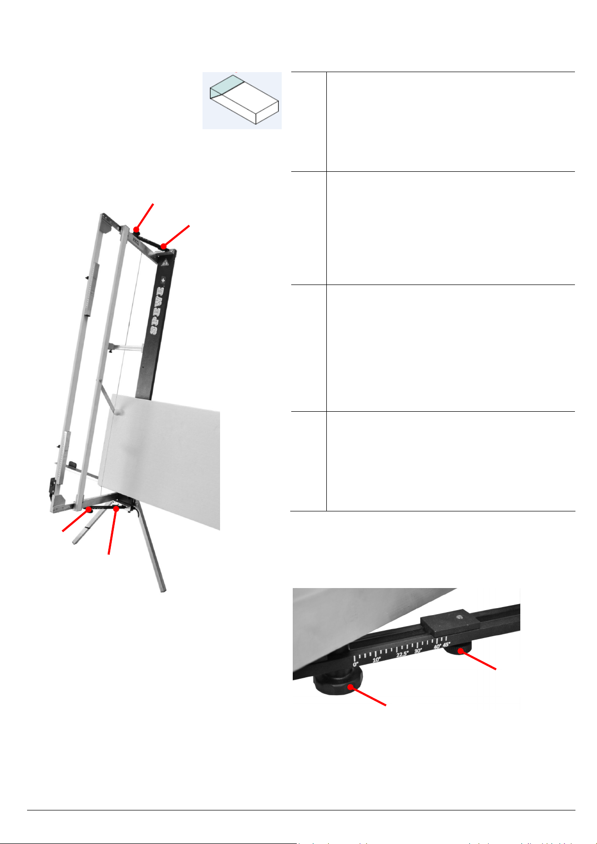
Fig. 1
2
1
D
Klappfuss (1) in C-Profil einschieben und festziehen.
Freistellstütze (2) ontieren, sofern das Gerät freige-
stellt werden öchte
F
Insérer le support arrière (1) en C-section et ser-
rer.
Le soutien des cultures (2) de ontage, à oins
que l'équipe ent serait exe pté
I
Inserire il supporto posteriore (1) in C-sezione e strin-
gere.
Sostegno delle colture (2) ontare, a eno che l'ap-
parecchio sarebbe stato esonerato
GB
Insert the rear stand (1) in C-section and tighten.
Crop support (2) ount, unless the equip ent
would be exe pted.
.
D
F
I
GB

04-2011 890SL 11 - 19
Inbetriebnahme <> Installation <> Messa in funzione <> Setting the Device Up
5
6
4
Fig. 2
D
Sterngriff (3) oben und unten lösen, Schneidbü-
gel (4) aufklappen und Sterngriffe (3) fixieren.
Auflageschienen (5+6) abschwenken.
Netzkabel abwickeln und an 230V Netz an-
schliessen.
F
Dévissez les poignées en étoile (3) en haut et en
bas, dépliez l’étrier de coupe (4) et resserrez les
poignées en étoile (3). Dépliez les rails de sup-
port (5+6).
Déroulez le câble de raccorde ent au réseau et
raccordez le au 230V.
I
Allentare l’i pugnatura a stella (3) superiore e
inferiore, ribaltare l’archetto da taglio (4) e fis-
sare le i pugnature a stella (3). Oscillare le gui-
de di supporto (5+6) verso il basso.
Disavvolgere il cavo di rete e collegarlo ad una
rete di 230V.
GB
Release star knob (3) at botto and top, fold
back cutting bow (4) and fixate star knob(3). Pull
out bearing rail (5+6).
Unravel power cable and connect to 230V
power outlet
3
3
04-2011 890SL 12 - 19
Inbetriebnahme <> Installation <> Messa in funzione <> Setting the Device Up
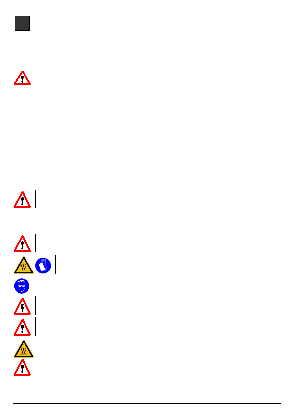
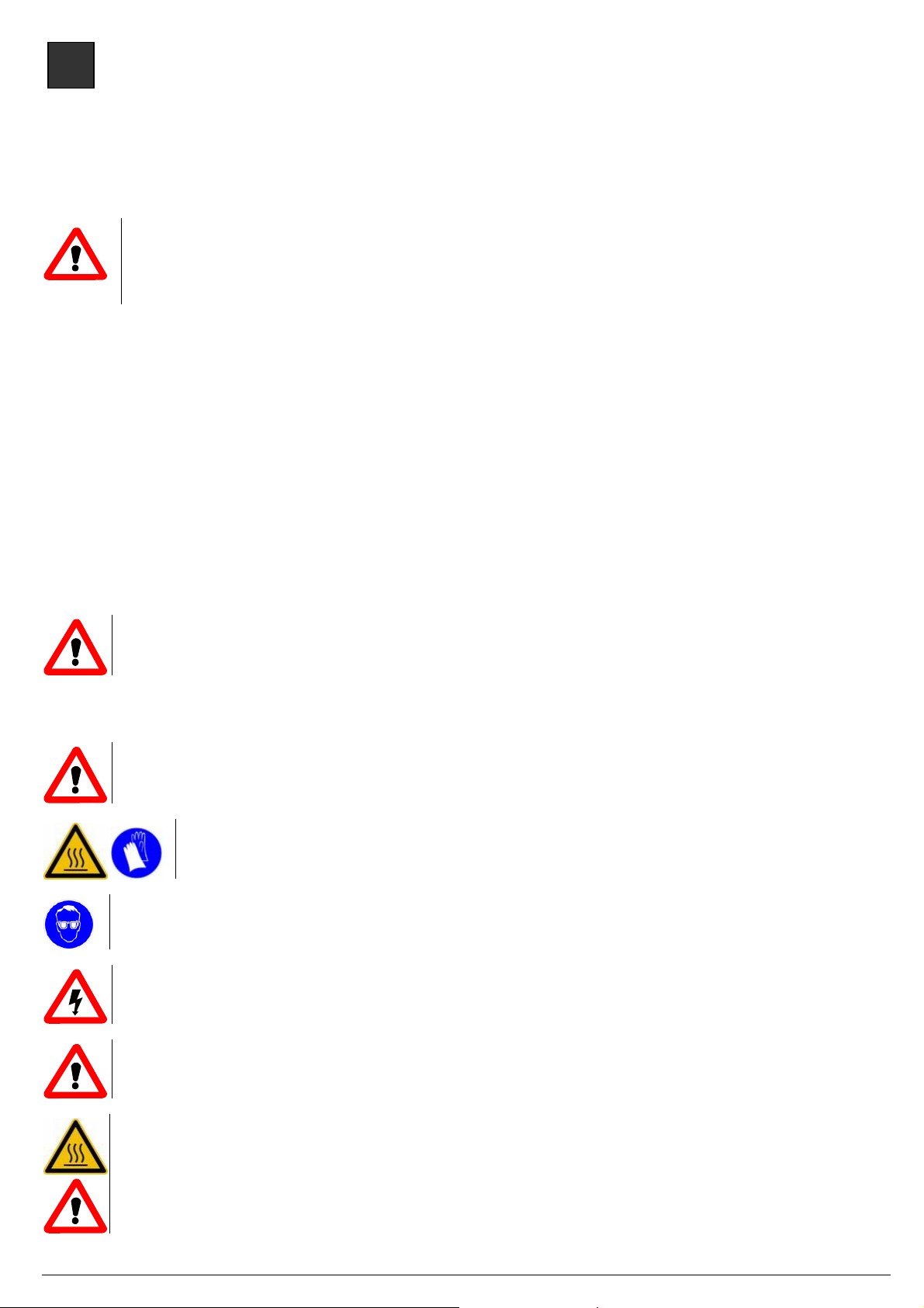
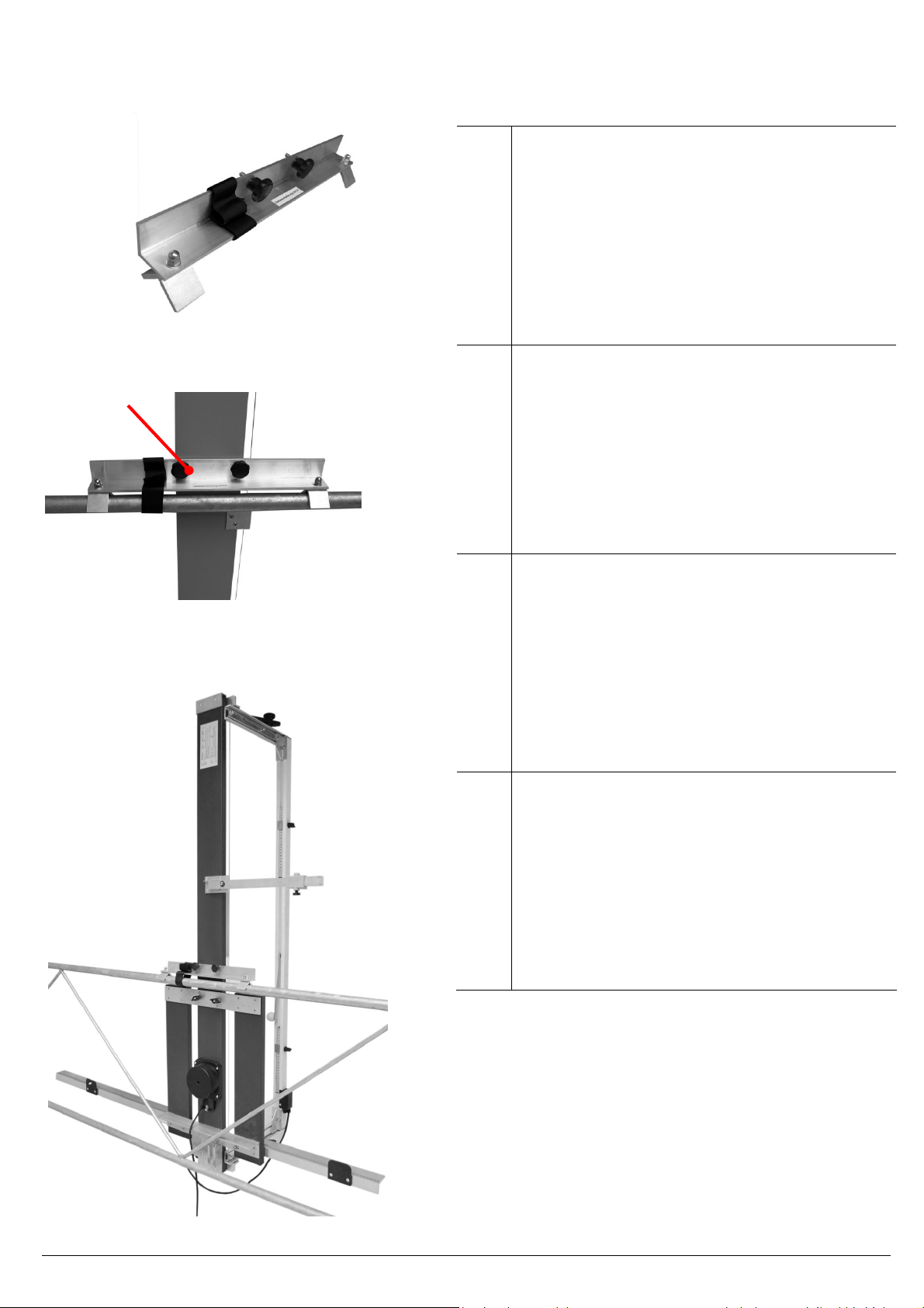
Variante 2:
D
Geländerhalterung (Optionales Zubehör)
(Art.-Nr. 14070068)
Geländerhalterung für senkrechten Geräteeinsatz
a Rückengeländer.
Montage:
Geländerhalterung an Rückseite des Gerätes ittels
beiliegenden Sterngriffschrauben (7) in die dafür
vorgesehenen Gewindebüchsen ontieren.
F
Support de balustrade (Accessoires optionnels)
(Art.-Nr. 14070068)
Support de balustrade pour une utilisation de l'ap-
pareil en position verticale sur la balustrade.
Montage :
Montez le support de balustrade au dos de l'appareil
à l'aide des vis papillons ises à disposition (7) en
les plaçant dans les filetages prévus à cet effet.
I
Supporto per parapetto (Accessorio optional)
(Nr. 14070068)
Supporto per parapetto per l’uso dell’apparecchio in
senso verticale su una ringhiera posteriore.
Montaggio:
Montare il supporto per parapetto sul lato posterio-
re dell’apparecchio con le viti con anopola a cro-
ciera (7) nelle apposite bussole filettate.
GB
Scaffolding support (Optional accessory)
(Nr. 14070068)
Scaffolding support for vertical use of tools in the
rear handrail.
Assembly:
Mount the scaffolding support on the rear of the
Tool in the tapped bush eant for it with the aid of
the attached star handle screws (7).
7
Fig. 3
Fig. 4
Fig. 5

04-2011 890SL 13 - 19
Schnittvarianten <> Variantes de coupes <> Varianti di taglio <> Cutting variants
D
Gerader Schnitt:
Bügel (8) vor de Zuschnitt herausziehen, Gerät
einschalten (9), Platte bis zu Zuschnitt ass
vorschieben und Zuschnitt ausführen.
F
Coupe droite :
Sortir l’étrier (8) avant la coupe, Pousser le panneau
(9) jusqu’à la cote de coupe et laisser l’étrier dans le
panneau.
I
Taglio rettilineo:
Estrarre l’archetto (8) pri a del taglio, pre ere il
pannello fino (9) alla isura di taglio desiderata e la-
sciare l’archetto nel pannello.
GB
Straight cut:
Pull out bracket (8) before cutting, push board (9)
forwards to cutting di ension and allow bracket to
dive into board.
D
Falz:
Tiefenbegrenzer (10) abschwenken. Falztiefe oder
Auftrenndicke einstellen. Dä platte einlegen,
Platte bis zur gewünschten Ausschnitt arkierung
vorschieben, Falz durch herausziehen des Schneid-
bügel ausschneiden. Mit dieser Einstellung können
auch ganze Platten aufgetrennt werden.
F
Coupe de rainure :
Poser la butée de profondeur (10). Régler la profon-
deur de rainure ou l’épaisseur de coupe . Poser le
panneau isolant, Avancer le panneau jusqu’au ar-
quage de découpe voulu, Soulever l'étrier de dé-
coupe et découper le pli. Des pan-neaux co plets
peuvent être découpés avec ce réglage.
I
Taglio piegato:
Posizionare il li itatore di profondità (10) in per-
pendicolare. Deter inare una profondità o spessore
di scanalatura. Inserire il pannello isolante, far a-
vanzare il pannello fino alla arcatura di taglio desi-
derata, sollevare l’archetto per taglio e tagliare la
piega. Con questo siste a è anche possibile isolare
interi pannelli.
GB
Seam:
Place depth li iter (10). Set sea depth or
separating thickness. Insert insulation board, push
the board forward to the cutting arking desired,
lift the cutting bracket and cut out sea . With this
setting, entire boards can also be separated.
8
9
Fig. 6
Fig.. 7
10
10
10

04-2011 890SL 14 - 19
Schnittvarianten <> Variantes de coupes <> Varianti di taglio <> Cutting variants
12
D
Schrägschnitt:
Plattenauflage (6) bis zur gewünschten Neigung
anheben, Feststeller (11) nachschieben und fi-
xieren.
F
Coupe en biais :
Soulevez le support de plaque (6) jusqu’à
l’inclinaison désirée, Poussez le curseur (11) et ser-
rez la vis.
I
Taglio obliquo:
Sollevare il supporto piattafor a (6) fino
all’inclinazione desiderata, spingere in avanti il di-
spositivo di fissaggio (11) e fissarlo.
GB
Slope cut:
Lift and adjust platter surface to desired angle (6),
and secure (11)
6
11
12
Fig. 8
Fig. 9
D
90°-Justierung:
Konterschraube (12) lösen, Schnittwinkel neu
ausrichten und Schraube wieder fixieren.
F
Ajustage à 90 ° :
Desserrez la vis (12), odifiez l'angle de coupe et
fixez de nouveau la vis.
I
Regolazione a 90°:
Allentare la vite (12) regolare l’angolo di taglio e fis-
sare nuova ente la vite.
GB
90°-alignment:
Loosen the screw (12), adjust the cutting angle again
and fix the screw again.
04-2011 890SL 15 - 19
Schnittvarianten <> Variantes de coupes <> Varianti di taglio <> Cutting variants
Fig. 11 3
13
D
Gehrungsschnitt:
Gehrung auf Dä platte übertragen und in Gerät
einlegen. Sterngriffe (3) lösen, Schneidbügel ab-
schwenken bis Gehrung it Markierung auf der
Dä platte übereinsti t und Sterngriffe fixieren.
Für Schnittwiederholungen Feststeller (13) an
Sterngriff schieben und fixieren.
F
Onglets :
Transférer l’onglet sur le panneau isolant que vous
placerez dans l‘appareil. Desserrer la poignée étoile
inférieure (3), tourner l’étrier jusqu’à ce que l’onglet
coïncide avec le arquage sur le panneau et fixer la
poignée étoile. Pousser le curseur (13) pour les cou-
pes répétitives, puis le pousser et le fixer par la poi-
gnée étoile.
I
Taglio ad angolo:
Trasferire il taglio ad angolo sul pannello isolante e
inserirlo nell’apparecchio. Allentare l’i pugnatura a
stella (3), ruotare l’archetto per taglio fino a co ba-
ciare la arcatura sul pannello isolante e fissare
l’i pugnatura a stella. Per l’esecuzione di tagli ad
angolo ripetuti, spostare e fissare il corsoio (13) nel-
le parti superiore e inferiore sull’i pugnatura a stel-
la
GB
Mitre cut:
Transfer itre to insulation board and insert in
equip ent. Loosen star handle (3) at the botto ,
swerve cutting bracket until itre atches the i-
tre on the insulation board and secure star handle.
For repeat cuts, push slide (13) at botto on star
handle and secure it.
3
3
13
13
Fig. 10

04-2011 890SL 16 - 19
Justierung <> Ajustage <> Torsiometrica <> Adjustment
Störungsursachen <> Les problèmes potentiels <> otenziali problemi <> otential problems
Fig. 12
Fig. 13
14
15
D
90°-Schnittwinkel kann ittels Reiter (14) exakt
nachjustiert werden.
F
Un angle de coupe de 90° peut être ajusté avec
précision au oyen du curseur (14).
I
L’archetto per taglio a 90° può essere nuova-
ente regolato in odo esatto ediante il cor-
soio (14).
GB
90° cutting angles can be readjusted precisely
with a slide (14).
D
Störungsursachen / Störungsbehebung
Sicherung ersetzen:
Dreh- und Druckschraube (15) für die Feinsicherung
entfernen, defekte Sicherung ersetzen und Schraube
wieder eindrehen.
Feinsicherung 5x20mm
F
Les problèmes potentiels et de dépannage
Remplacez le fusible:
Retirez la vis rotative et à pression (15) pour les fusi-
bles fins, re placez les co posants défectueux et
repositionnez la vis.
Fusible 5x20mm
I
otenziali problemi / Risoluzione dei problemi
Sostituire il fusibile:
girare e ri uovere la vite (15) per fusibili fine, sosti-
tuire difettoso Si-assicurazione e vite del bullone.
Fusibili 5x20mm
GB
otential problems / troubleshooting
Replace fuse:
turn and re ove screw (15) for fine fuses, replace
defective Si-assurance and bolt screw.
Fuses 5x20mm
04-2011 890SL 17 - 19
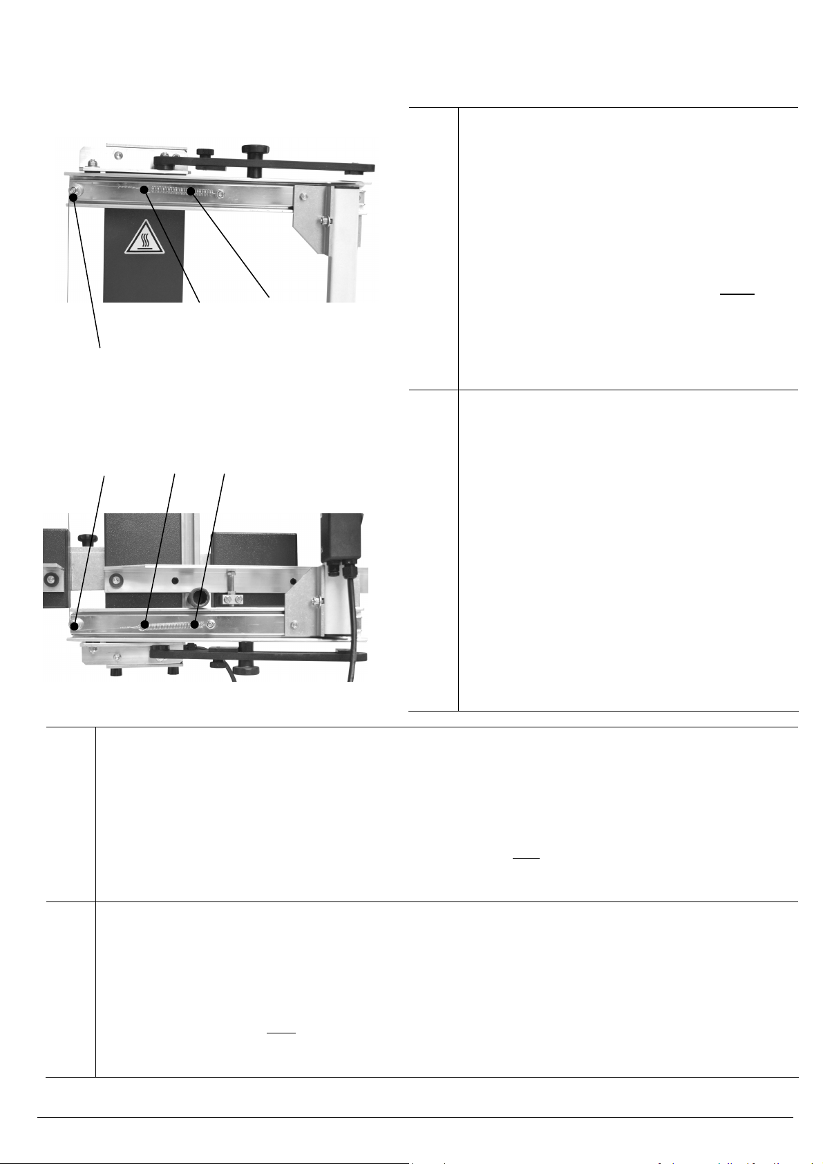
Draht ersetzen <> Remplacer <> Sostituzione e trazione del filo <> Replacing
D
Draht ersetzen, Draht nachziehen
Gerät vo 230V Netz trennen.
Bei eine Drahtriss den restlichen Draht vo Gerät
entfernen. Von der Ersatzdrahtspule ungefähr den
erforderlichen Draht ablösen.
A einen Drahtende eine kleine Schlaufe (16) bil-
den, den Draht an der ersten Feder (17) einhängen,
über die erste (18) und zweite (19) Drahtführungs-
rolle bis zur zweiten Zugfederöse (20) führen. Die
zweite Feder (21) so stark spannen, dass beide Fe-
dern u ca. 2-3 c länger werden. Danach den
Draht einige Male u sich selber wickeln (Schlaufe
bilden) und restlichen Draht abkle en.
Achten Sie beim Schneiden hin und wieder, dass
die Zugfedern jeweils genügend gespannt sind.
F
Remplacer / retendre le filament
Débrancher l’appareil du secteur 230V.
En cas de rupture de fila ent, enlevez le reste de fil
de l’appareil. Dévidez la quantité approxi ative de
fila ent nécessaire de la bobine de rechange.
Faites une petite boucle à une extré ité (16), ac-
crochez le fila ent au pre ier ressort (17), passez
le par le rouleau de guidage (18) jusqu’au deuxiè e
(19), engagez le sur le deuxiè e anneau du ressort
de traction (20) et co encer à tendre le 2
è e
res-
sort (21) jusqu’à ce que les deux ressorts
s’allongent d’environ 2-3 c . Puis enroulez le fil de
plusieurs tours sur lui- ê e (boucle) et coincez le
reste de fila ent.
Assurez-vous de te ps à autre lors de la coupe que
les ressorts de traction sont toujours suffisa ent
tendus.
I
Sostituzione e trazione del filo
Ali entare l’apparecchio a 230 V.
In caso di rottura del filo, ri uovere il filo residuo sull’apparecchio. Allentare il filo necessario dalla bobina del
filo di rica bio.
Realizzando un piccolo cappio (16) a un’estre ità, il filo si aggancia alla pri a olla (17), passa attraverso il
rullo guidafilo (18) fino al secondo (19), viene teso dal secondo anello della olla di tensione (20) e inizia a
tendere la seconda olla (21) tanto intensa ente da allungare le due olle di circa 2-3 c . Successiva ente,
avvolgere legger ente il filo su se stesso (cappio) e fissare il filo residuo.
Verificare saltuaria ente ediante il taglio che le olle di tensiona ento siano adeguata ente tese.
GB
Replacing, tightening wire
Disconnect equip ent fro 230V ains.
If a wire snaps, re ove the re aining wire fro the equip ent. Cut off the approxi ately required wire fro
the spare coil.
Make a s all loop (16) at one end, connect the wire to the first spring (17), guide it via the wire-guiding pulley
(18) through to the second one (19), pull it through the second tension spring eye (20) and start to tighten the
second spring (21) so that both springs are extended by approx. 2-3 c . Then wrap the wire several ti es
around itself (loop) and cut off the re aining wire.
When cutting, check occasionally that the tension spring is sufficiently tight.
16
17
18
19
20
21
Fig. 14
Fig. 15

04-2011 890SL 18 - 19
Ersatzteilliste / Nomenclature / Elenco parti di ricambio per modello / Spare parts list
D Ersatzteilliste 890SL
1 15059001 Anschlagreiter links
2 15089036
Auflageschiene links it Skala und Verbreiterung
3 15089035
Auflageschiene rechts it Skala und Verbreiterungen
4 15055016 Drahtführungsrolle 16x5 (Oben oder Unten)
5 15190005S Flügelgriff M6 zu Tiefenbegrenzer
6 150790119 Kugelführung Oben, it Drahtrolle, Zugfeder, Befestigungswinkel
7 150790120 Kugelführung Unten, it Drahtrolle, Zugfeder, Befestigungswinkel
8 15090076 Skala 100c , Re 0-100
9 15090077 Skala 50c , Li 50-0
10 15089010 Schaltergehäuse kpl. it Wippenschalter, Sicherungshalter, Verbindungskabel
10.1 15000040 Feinsicherung 5x20 , 10 Stk
11 15990013 Sterngriff - Schraube M6x20 (Geländerhalterung)
12 15500056 Sterngriff utter 32-M6 für Schwenkar Oben oder Unten
13 15079024 Tiefenbegrenzer ko plett
14 15089008 Trafo RKT 230V, 31V, it 3 Gu ikabel
15 15350024 Zugfeder 50
16 150790109 Freistellstütze it 2 Flügelgriffen
17 14070072 Ersatzdraht 0.65 / 20
1
6
3,8
10.1
17
11
10
3,8
4
5,13
14
2, 9
6
7
10
12
15
16
9

04-2011 890SL 19 - 19
F Nomenclature 890SL
1 15059001 Butée gauche
2 15089036
Barre de support de gauche avec graduation et extension
3 15089035
Barre de support de droite avec graduation et extension
4 15055016 Rouleau guide-fil16x5
5 15190005S Poignée papillon M6 pour le li iteur de profondeur
6 150790119 Curseur à roule ent à billes supérieur, avec rouleau de fil, ressort de traction, cornière
7 150790120 Curseur à roule ent à billes inférieur, avec rouleau de fil, ressort de traction, cornière
8 15090076 Echelle graduée alu 1 , dr. 0-100
9 15090077 Echelle graduée alu 50c , g 50-0
10 1508910 assy boîtier du co utateur. avec interrupteur à bascule, porte-fusible
10.1 15000040 Fusible 5x20 , 10 pcs
11 15990013 Vis à poignée étoile M6x20 (fixation ra barde)
12 15500056 Ecrou pour poignée étoile 32-M6 pour bras basculant
13 15079024 Li iteur de profondeur co plet
14 15089008 Transfo 230V, 31, av 3 câble caoutchouc, coupe-circuit auto
15 15350024 Ressort de traction
17 14070072 Bobine de fila ent de rechange 20
I Elenco parti di ricambio per modello 890SL
1 15059001 Scorrevole battuta sinistro
2 15089036
Scorri ento della barra di posizione con scala graduata e estensione di larghezza
3 15089035
Scorri ento della barra di posizione con scala graduata e estensione delle larghezze
4 15055016 Rullo guidafilo 16x5
5 15190005S I pugnatura a stella M6 per li itatore di profondità
6 150790119 Guidarullo sferico superiore, con rullo filo, olla di tensione, bullone a staffa
7 150790120 Guidarullo sferico inferiore, con rullo filo, olla di tensione, bullone a staffa
8 15090076 Scala allu inio 1 , Re 0-100
9 15090077 Scala allu inio 50 c , Li 50-0
10 15089010 Switch alloggio co pl. con interruttore, fusibile
10.1 15000040 Fusibile 5x20 , 10 pz
11 15990013 I pugnatura a stella – viti M6x20 (supporto parapetto)
12 15500056 Dado a stella 32-M6 per braccio orientabile
13 15079024 Li itatore di profondità co pleto
14 15089008 Trasfor atore 230V, 31V, con cavo di go a da 3 , PLC di sicurezza
15 15350024 Molla di tensione
17 14070072 Bobina di riserva per il filo di etallo 20
GB Spare parts list 890SL
1 15059001 End stop left
2 15089036
Left Bearing Rail with Scale and Extensions
3 15089035
Right Bearing Rail with Scale and Extensions
4 15055016 Wire-guiding pulley 16x5
5 15190005S Wing handle M6 for depth li iter
6 150790119 Ball slide top, with wire pulley, tension spring, fitting angle
7 150790120 Ball slide botto , with wire pulley, tension spring, fitting angle
8 15090076 Di ension alu iniu 1 , right 0-100
9 15090077 Di ension alu iniu 50c , left 50-0
10 15089010 Switch housing assy. with rocker switch, fuse holder
10.1 15000040 Fuse 5x20 , 10 Pcs
11 15990013 Star handle screw M6x20 (rail cla p)
12 15500056 Star handle nut 32-M6 for pivot ar
13 15079024 Depth li iter co plete
14 15089008 Transfor er 230V, 31V, with 3 rubber cable, safety achine
15 15350024 Tension spring
17 14070072 Replace ent Wire Reel 20
Other manuals for 890SL
1
This manual suits for next models
2
Other SPEWE Cutter manuals

SPEWE
SPEWE 1900L-30 User manual

SPEWE
SPEWE DT127-30 User manual

SPEWE
SPEWE Isoturbo 6005L-30 Operation and maintenance manual

SPEWE
SPEWE DT104-28 User manual

SPEWE
SPEWE ES-5300 User manual

SPEWE
SPEWE Isoturbo 6000L S-05 User manual

SPEWE
SPEWE 890SL User manual

SPEWE
SPEWE 1900L-30 User manual

SPEWE
SPEWE 410GTL 2014 User manual

SPEWE
SPEWE 3500EL-40 Manual

SPEWE
SPEWE ES-212SL-30 User manual

SPEWE
SPEWE 112SL-28 User manual

SPEWE
SPEWE 1900L-30 User manual

SPEWE
SPEWE 112GT-28 User manual

SPEWE
SPEWE 1200169 User manual

SPEWE
SPEWE 212GS-30 User manual

SPEWE
SPEWE 5300S User manual

SPEWE
SPEWE ES-212-30 User manual

SPEWE
SPEWE 392GT User manual

SPEWE
SPEWE DT104-28 User manual


