SPEWE 600SL User manual
1901178 / 07-2013
600SL
1
D
Glühdraht-Schneidegerät
Sicherheitshinweise
2
Bedienungsanleitung
3-7
F
Découpeuse a filament chauffant
Instructions de sécurité
2
ode d’emploi type
3-7
I
Trancia a filo incandescente
Avvisi di sicurezza
2
Istruzioni per l’uso modello
3-7
GB
Heated Wire Cutting Device
Safety Instructions
2
Operating Instructions
3-7
6
66
60
00
00SL
0SL0SL
0SL
od. 2013
Art.-Nr. 1000151
1901178 / 07-2013
600SL
2
D
Sicherheitshinweise - Vorwort
Diese Anleitung ist die Grundlage zur Bedienung des Glühdraht-Schneidegeräts. Sie verdient Ihre volle Aufmerksamkeit.
Bevor Sie mit irgendwelchen Arbeiten an oder mit dem Gerät beginnen, verpflichten wir Sie, die vorliegende Anleitung
und die separaten Sicherheitsbestimmungen bis zum Schluss sorgfältig durchzulesen. Bestehen irgendwelche Unklar-
heiten, sprechen Sie uns umgehend dazu an. Nehmen Sie das Gerät nicht in Betrieb solange Unklarheiten bestehen. it
der Inbetriebnahme des Gerätes bestätigen Sie, dass Sie die Anleitung gelesen und verstanden haben und somit die Be-
triebsverantwortung übernommen haben.
F
Remarques de sécurité concernant les coupeuses à filament incandescent – Préface
Ce mode d’emploi est la base pour le maniement de la coupeuse à filament incandescent. Veuillez le consulter avec
beaucoup d’attention.
Avant de commencer quelques travaux que ce soit ou avant d’utiliser la coupeuse, nous vous engageons à lire le pré-
sent mode d’emploi et les remarques de sécurité séparé a minutieusement jusqu’à la fin. S’il y a quelques confusions,
n’hésitez pas à nous contacter immédiatement. Ne mettez pas la coupeuse en service tant qu’il y a des confusions. Avec
la mise en service de la coupeuse, vous confirmez que vous avez lu le mode d’emploi et que vous l’avez compris et ainsi
vous prenez en charge la responsabilité du bon fonctionnement.
I
Avvisi di sicurezza per la trancia a filo incandescente - Premssa
Le presenti istruzioni sono la base per l’uso della taglierina a filo incandescente.
Prima di iniziare qualsiasi operazione sull’apparecchio o con l’apparecchio, vi chiediamo di impegnarvi a leggere atten-
tamente le presenti istruzioni e la avvertenze di sicurezza separato fino alla fine. Qualora dovessero esservi dei punti
non chiari, contattateci immediatamente e parlatecene. Non mettete in funzione l’apparecchio fino a quando sussistono
questi dubbi. ettendo in funzione l’apparecchio, confermate di avere letto le istruzioni e di esservi assunto la responsa-
bilità del relativo esercizio.
GB
Hot wire cutter safety advice and instructions manual - Foreword
These instructions must be read before using the hot wire cutter. Please read them carefully.
Before you begin any work or begin using the tool, you must carefully read this introduction and the separate safety ad-
vice . If you have any queries, please do not hesitate to contact us. Do not use the tool if you continue to be unsure
about any aspect. When you begin to use the tool, you tacitly confirm that you have read and understood the introduction
and that you take full responsibility for the operation of the tool.
Daten | Details | Dati | Details |
D
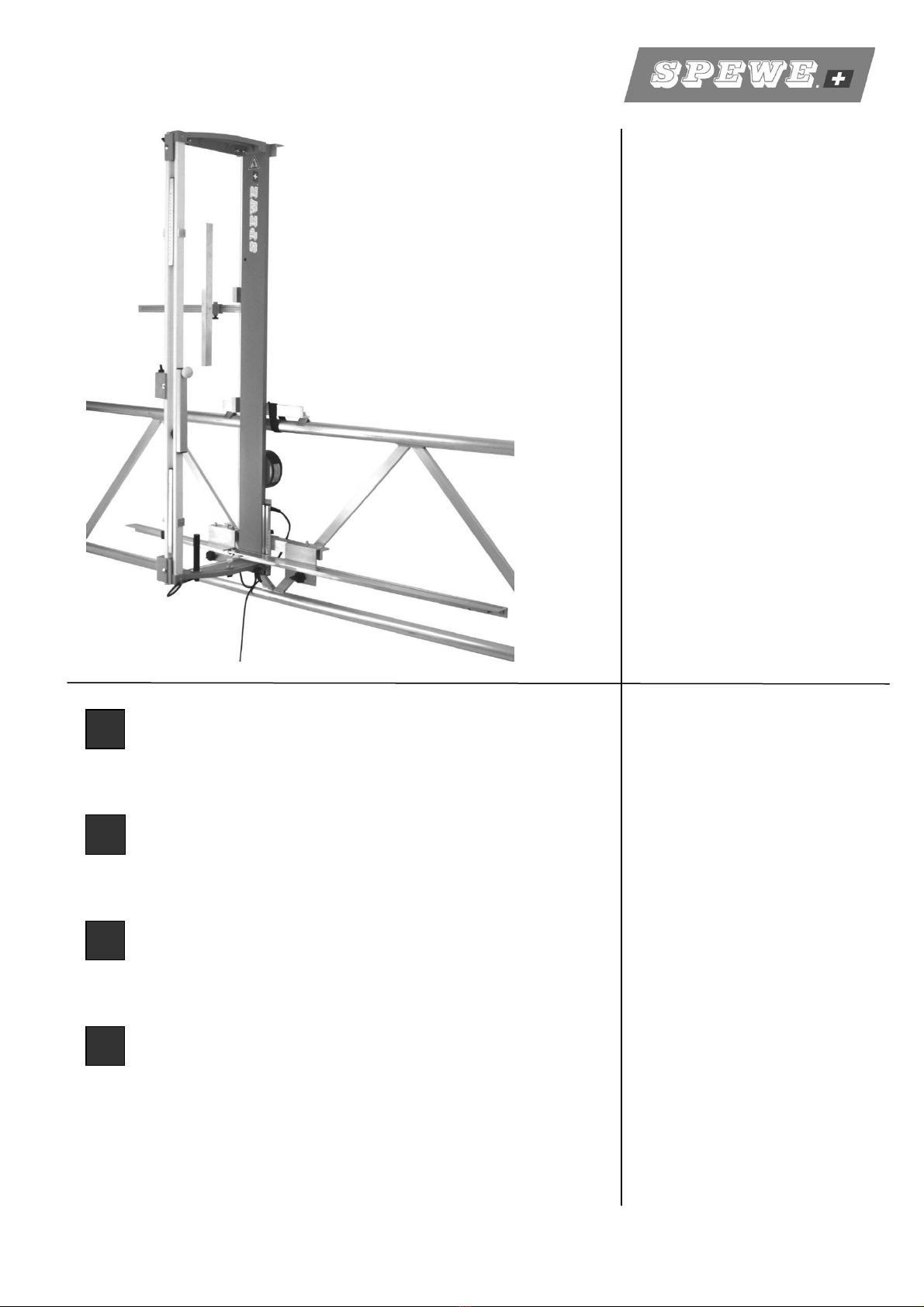
Lieferumfang: Glühdraht-Schneidegerät Typ 600SL mit integriertem Trafo, Geländerhalterung, Ersatzdrahtspule 9m,
Flachzange, Ersatzsicherung, Bedienungsanleitung.
Technische Daten: Schnittlänge: 127 cm Schnitttiefe: 21 cm Gewicht Gerät: 11.0 kg
Zuschnitt : Thermisch Stromversorgung: 230V/50 Hz
F
Volume de livraison : Coupeuse à filament incandescent type 600SL avec transformateur intégré, Support de balustrade, pince
plate, filament de rechange (9 m), fusible de rechange, mode d'emploi.
Caractéristiques
techniques :
Longueur de coupe: 127 cm Profondeur de coupe 21 cm Poids de l’appareil: 11.0 kg
Découpe : thermique Alimentation : 230V / 50 Hz
I
Corredo di fornitura : Apparecchio di taglio a filo incandescente tipo 610SL con trasformatore integrato, supporto per parapetto,
pinza piatta, filo di ricambio (9 m) fusibile di ricambio, istruzioni per l’uso.
Dati tecnici: Lunghezza di taglio: 127 cm Profondità di taglio: 21 cm Peso: 11.0 kg
Taglio: termico Alimentazione: 230V / 50 Hz
GB
Scope of delivery: Hot-wire cutting tool Type 610SL with integrated transformer, scaffolding support, flat nose pliers, re-
placement conductor (9m), replacement fuse, operating instructions.
Technical details: Cutting length: 127 cm Cutting depth: 21 cm Equipment weight: 11.0 kg
Cut: Thermal Power supply: 230V / 50 Hz
D
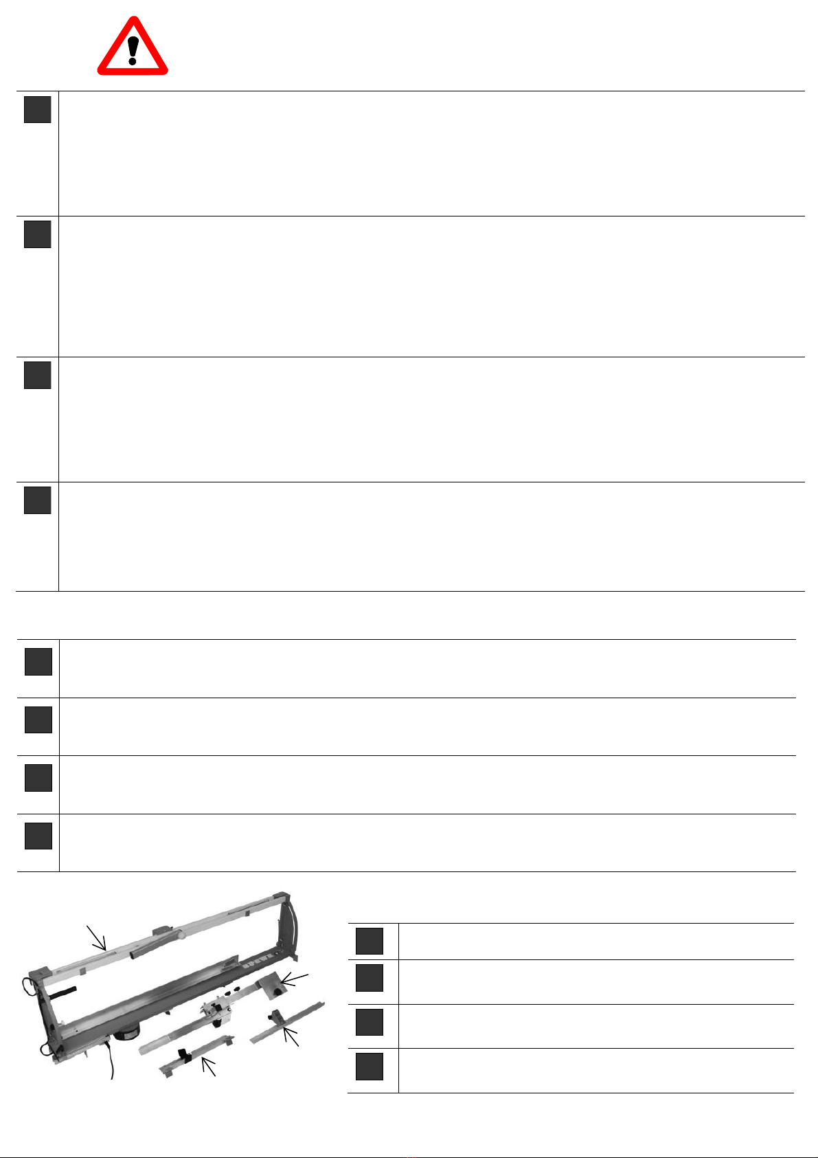
Lieferumfang: Schneidegerät (A), Geländerhalterung (B)
Plattenauflagehalterung (C), Plattenanschlag (D)
F
Volume de livraison: Découpeuse (A), Support de balustrade (B)
Dispositif de blocage de support de panneau (C), Ta uet gauche (D)
I
Corredo di fornitura: Taglierina (A), Supporto per parapetto (B)
Supporto di appoggio piastra (C), Battuta di sinestra (D)
GB
Scope of delivery: Cutting e uipment (A), Scaffolding support (B)
Board resting holder (C), Stop left (D)
Fig. 1
A
B
D
C

1901178 / 07-2013
600SL
3
Inbetriebnahme | Installation | Messa in funzione | Setting the Device p
D
Plattenauflagehalterung
Plattenauflagehalterung (1) an Geräte-
rückseite in Schlitze einschieben und mit
Flügelgriffen (2) fixieren.
F
Dispositif de blocage de support de
panneau
Pousser le dispositif de blocage de support
de panneau (1) dans la fente à la face
arrière de l’appareil et fixer les poignées à
ailettes (2).
I
Supporto di appoggio piastra
Far scorrere il supporto di appoggio piastra
(1) sulle scanalature sulla parte posteriore
del dispositivo e fissare con un raccordo a
farfalla (2).
GB
Board resting holder
Slide board resting holder (1) into back-
side of slotted profile and tighten with
wing bolts (2).
D
Geländerhalterung für senkrechten Gerä-
teeinsatz am Rückengeländer.
ontage: Geländerhalterung (3) an Rück-
seite des Gerätes montieren.
F
Support de balustrade pour une utilisation
de l'appareil en position verticale sur la ba-
lustrade:
ontage : ontez le support de balus-
trade (3) au dos de l'appareil.
I
Supporto per parapetto per l’uso
dell’apparecchio in senso verticale su una
ringhiera posteriore
ontaggio:
ontare il supporto per parapetto (3) sul la-
to posteriore dell’apparecchio
GB
Scaffolding support for vertical use of
tools in the rear handrail
Assembly:
ount the scaffolding support (3) on the
rear of the Tool.
Fig. 5
3
1
2
2
Fig. 2
Fig. 3
Fig. 4
3

1901178 / 07-2013
600SL
4
Inbetriebnahme | Installation | Messa in funzione | Setting the Device p
D
Grundsätzlich:
Durch das Einschalten (7) wird der Draht erwärmt. Eine Aufwärmzeit ist nicht nötig. Der Zuschnitt
kann sofort erfolgen
F
En principe :
Par en allumer (7), le fil de fer est chauffé. Un temps de réchauffement n'est pas nécessaire. La
coupe peut être effectuée tout de suite
I
Istruzioni di base:
Il filo viene riscaldato mediante l'interruttore (7). Non occorre attendere il raggiungimento di una de-
terminata temperatura, bensì è possibile procedere immediatamente con le operazioni di taglio.
GB
Fundamental principle:
By switching on (7) the wire is warmed. A pre-heating period is not necessary. The cut can be made
immediately
D
Schneidegerät auf Geländerstange setzen.
Klettband (4) um Geländerstange legen.
Das Gerät ist somit gegen ein Herunterfal-
len gesichert.
Auflageschiene (5+6) abschwenken.
Trafo an Stromnetz anschliessen.
F
Placez la coupeuse sur la barre de l'écha-
faudage comme sur l'illustration.
Protection de l'appareil :
Enroulez de la bande Klett autoagrippante
(4) autour de la barre de la balustrade.
C'est ainsi que l'appareil est protégé contre
les chutes.
Inclinez le rail de guidage (5+6)
Raccordez le cable au 230V
I
Applicare l’apparecchio di taglio sulla barra
del parapetto secondo le modalità illustrate
nella figura.
Blocco dell’apparecchio:
Avvolgere il nastro di velcro intorno (4) alla
barra del parapetto per impedire che
l’apparecchio possa cadere.
Far oscillare verso il basso la guida di sup-
porto (5 + 6).
Collegare il alimentazione di trasformatore.
GB
Put the cutting tool on the scaffolding rod
as in the illustration.
Equipment safety:
Put the Velcro strip (4) around the scaffold-
ing rod. The tool is thus protected from fall-
ing down.
Pull out bearing rail (5+6)
Attaching equipment at power supply sys-
tem.
Fig. 6
Fig. 7
4
6
5
7

1901178 / 07-2013
600SL
5
Optionales Zubehör | Accessoires | Accessorio | accessory
Schnittvarianten | Variantes de coupes | Varianti di taglio | Cutting variants
D
Gerader Schnitt: Bügel (8) vor dem Zuschnitt
herausziehen, Dämmplatte bis zum Zuschnittmass
vorschieben und Zuschnitt ausführen.
Falz: Falztiefe oder Auftrenndicke einstellen (9).
Dämmplatte einlegen, Platte bis zur gewünschten
Ausschnittmarkierung vorschieben, Falz durch
herausziehen des Schneidbügel (8) ausschneiden.
F
Coupe droite: Sortir l’étrier (8) avant la coupe,
Pousser le panneau jusqu’à la cote de coupe et
laisser l’étrier dans le panneau.
Coupe de rainure: Régler la profondeur de rai-
nure ou l’épaisseur de coupe (9).
Poser le panneau isolant, Avancer le panneau
jusqu’au marquage de découpe voulu, Soulever
l'étrier de découpe (8) et découper le pli.
I
Taglio rettilineo: Estrarre l’archetto (8) prima del
taglio, premere il pannello fino alla misura di taglio
desiderata e lasciare l’archetto nel pannello.
Taglio piegato: Determinare una profondità o
spessore di scanalatura (9).
Inserire il pannello isolante, far avanzare il pannel-
lo fino alla marcatura di taglio desiderata, sollevare
l’archetto per taglio (8) e tagliare la piega.
GB
Straight cut: Pull out bracket (8) before cutting,
push board forwards to cutting dimension and al-
low bracket to dive into board.
Seam: Set seam depth or separating thickness (9)
Insert insulation board, push the board forward to
the cutting marking desired, lift the cutting bracket
(8) and cut out seam.
D
Nachrüstsatz
A: Klappfuss ohne Freistellstütze (1901709)
B: Freistellstütze (1901707)
F
Kit de rattrapage
A: Pied amovible sans cheville de fixation (1901709)
B: Cheville de fixation (1901707)
I
Retrofit kit
A: Gamba pieghevole, senza montante libero
(1901709)
B: ontante libero (1901707)
GB
Retrofit kit
A: Collapsible foot, without release support (1901709)
B: Release support (1901707)
8
9
Fig. 8
Fig. 9
9
A
B
1901178 / 07-2013
600SL
6
Schnittvarianten | Variantes de coupes | Varianti di taglio | Cutting variants
D
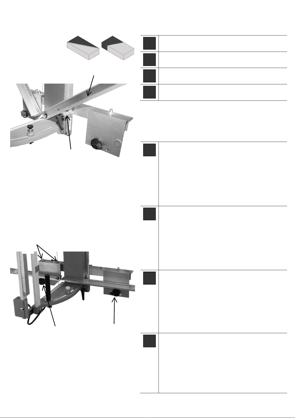
Schrägschnitt: Plattenauflage (10) abschwen-
ken, Feststeller (11) nachschieben und fixieren.
F
Coupe en biais : Détournez le butoir horizontal
(10), repoussez et fixez l'arrêt (11).
I
Taglio obliquo: Oscillare via l’arresto meccanico
longitudinale (10), spingere il fermo (11) e fissare.
GB
Slope cut: Swivel length stop (10), attach the
locking pin (11) and fix it.
D
90°-Justierung:
Flügelgriff (12) an Exzenterscheibe
lösen, Auflageschiene mit der Exzenterscheibe korrigie-
ren und Flügelgriff wieder fest fixieren. Somit bleibt die
90°-Justierung auch nach einem Schrägschnitt weiter
bestehen .
Zum Einstellen der linken Auflageschiene, Winkel oder
Dämmplatte über beide Auflageschienen legen. Höhen-
korrektur erfolgt mittels Gabelschlüssel an Hutmuttern
(13). Waagrechte Justierung mittels Exzenterscheibe
(14) vornehmen.
F
Ajustage à 90 ° :
Dévisser la poignée à ailettes (12)
du disque excen-trique, corriger la barre d’appui à l’aide
du disque excentrique et de nouveau fixer solidement la
poignée à ailettes. C’est ainsi qu’un ajustage de 90 °
reste également conservé après une coupe diagonale.
Afin de régler la barre d’appui gauche, poser la plaque
thermo-isolante sur les deux barres d’appui. La corre-
ction de la hauteur est effectuée à l’aide de la clé à
fourche sur l’écrou borgne à calotte (13). Effectuer
l’ajustage horizontal à l’aide du disque excentrique (14).
I
Regolazione a 90°:
Allentare il raccordo a farfalla
(12) sul disco dell’eccentrico, correggere le guide del
supporto con il disco dell’eccentrico e fissare di nuovo
bene il raccordo a farfalla. In questo modo la regola-
zione a 90° resterà invariata anche dopo un taglio incli-
nato. Per regolare la guida a sinistra, posizionare il pan-
nello isolante su entrambe le guide. Per la regolare
l’altezza utilizzare la chiave fissa sui dadi ciechi (13).
Per la regolazione orizzontale utilizzare il disco
dell’eccentrico (14)
GB
90°-alignment:
Loosen the wing grip (12) at the ex-
centric, correct the board rest with the excentric and
tighten the wing grip again. By doing this the 90°-
adjustment will also be kept after an angular cut.
For setting the left board rest, put insulation board over
both board rests.
Correct the height by turning the cap nuts with flat
wrench (13). ake vertical adjustments by means of the
excentric (14).
11
12
Fig. 11
13
Fig. 12
14
10
Fig. 10
1901178 / 07-2013
600SL
7
Schnittvarianten | Variantes de coupes | Varianti di taglio | Cutting variants
Störungsursachen | Les problèmes potentiels | Potenziali problemi | Potential problems
D
Gehrungsschnitt:
Gehrungsstab (15) lösen und nach oben schieben.
Dämmplatte in Abstellwinkel (16) setzen und bis
zur gewünschten Neigung anheben. Gehrungs-
stab (15) an Dämmplatte schieben und fixieren.
(Gehrung bleibt für Wiederholungsschnitte einge-
stellt)
F
Coupe en onglet :
Desserrez la barre d'onglet (15) et la pousser vers
le haut. Placez le panneau isolant en angle de dé-
brayage (16) et lever jusqu’à l’inclinaison désirée.
Poussez la barre d'onglet (15) jusqu'au panneau
isolant et la fixer. (L'onglet reste réglé pour les ré-
pétitions de coupe)
I
Taglio ad angolo:
Allentare la barra di bisellatura (15) spingendola
verso l’alto. Posizionare la lastra isolante nella
squadra di fermo (16) e sollevare fino ad ottenere
l’inclinazione desiderata.
Premere la barra di bisellatura (15) sulla lastra iso-
lante e procedere con il fissaggio (l’angolo di bisel-
latura regolato rimarrà impostato anche per i tagli
successivi.
GB
itre cut:
Release the mitre rod (15) and push it upwards.
Place the insulation board at the angle support(16)
and elevate it to the desired inclination.
Push the mitre rod (13) onto the insulation board
and fix it. (The mitre is set for repeat cuts)
D
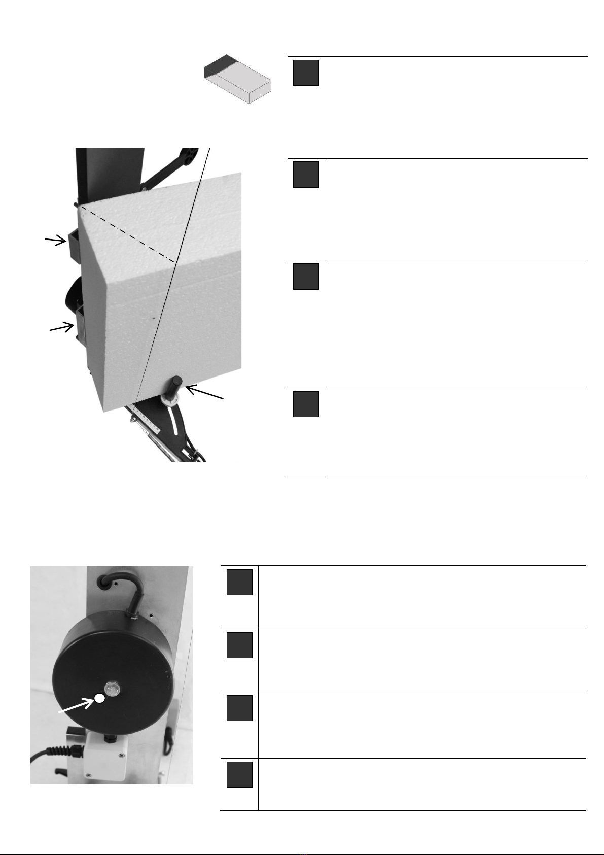
Störungsursachen / Störungsbehebung
Sicherung ersetzen: Dreh- und Druckschraube (17) für die Feinsiche-
rung entfernen, defekte Sicherung ersetzen und Schraube wieder ein-
drehen. (Feinsicherung 5x20mm)
F
Les problèmes potentiels et de dépannage
Remplacez le fusible: tourner et retirer la vis (17) pour les fusibles
fine, remplacer les composants défectueux Si-vis de l'assurance et de
boulons. (Fusible 5x20mm)
I
Potenziali problemi / Risoluzione dei problemi
Sostituire il fusibile: girare e rimuovere la vite (17) per fusibili fine,
sostituire difettoso Si-assicurazione e vite del bullone.
(Fusibili 5x20mm)
GB
Potential problems / troubleshooting
Replace fuse: turn and remove screw (17) for fine fuses, replace de-
fective Si-assurance and bolt screw. (Fuses 5x20mm)
15
16
16
Fig. 12
Fig. 13
Fig. 14
17
This manual suits for next models
1
Other SPEWE Cutter manuals

SPEWE
SPEWE 410GTL 2014 User manual

SPEWE
SPEWE 3500EL-40 Manual

SPEWE
SPEWE 212GS-30 User manual

SPEWE
SPEWE 1200169 User manual

SPEWE
SPEWE ES-5300 User manual

SPEWE
SPEWE 890SL User manual

SPEWE
SPEWE 5300S User manual

SPEWE
SPEWE 212SL-30 User manual

SPEWE
SPEWE Isoturbo 6005L-30 Operation and maintenance manual

SPEWE
SPEWE 791GT User manual

SPEWE
SPEWE 112GT-28 User manual

SPEWE
SPEWE ES-212-30 User manual

SPEWE
SPEWE 890SL User manual

SPEWE
SPEWE DT104-28 User manual

SPEWE
SPEWE 392GT User manual

SPEWE
SPEWE 112SL-28 Manual

SPEWE
SPEWE 1900L-30 User manual

SPEWE
SPEWE FD144T-30 User manual

SPEWE
SPEWE 1900ML-30 04 Series User manual

SPEWE
SPEWE ES-212SL-30 User manual


