manuals.online logo
Brands
  1. Home
  2. •
  3. Brands
  4. •
  5. Teknik
  6. •
  7. Indoor Furnishing
  8. •
  9. Teknik 5417593 User manual

Teknik 5417593 User manual

www.teknikoffice.co.uk
NOTE: THIS INSTRUCTION
BOOKLET CONTAINS IMPORTANT
SAFETY INFORMATION.
PLEASE READ AND KEEP FOR
FUTURE REFERENCE.
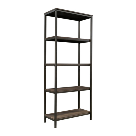
Shaker Style Bookcase with Doors
Model 5417593
Here's one for
the books.
Teknik
Table of Contents Assembly Tools Required
Part Identification
Hardware Identification
Assembly Steps
Français
Español
Safety
Warranty
Hammer
Not actual size
No. 2 Phillips Screwdriver
Tip Shown Actual Size
Skip the power trip.
This time.
3
4
5-22
23-25
26-28
29-30
31
Page 2
Part Identification
åWhile not all parts are labeled, some of the parts will have a label or an inked letter on the edge
to help distinguish similar parts from each other. Use this part identification to help identify similar parts.
Now you know
our ABCs.
A RIGHT END (1)
B LEFT END (1)
C2 TOP (1)
D BOTTOM (1)
E SHELF (1)
F BACK (1)
G DOOR (2)
H ADJUSTABLE SHELF (2)
I SMALL ADJUSTABLE SHELF (1)
J RIGHT LEG (1)
K LEFT LEG (1)
L BASE (1)
M TOP MOLDING (1)
N SHELF MOLDING (1)
O ADJUSTABLE SHELF MOLDING (2)
P SPACER (1)
Page 3
A
B
C2
D
E
F
G
H
I
K
L
M
N
O
H
O
P
G
J
Hardware Identification
åScrews are shown actual size. You may receive extra hardware with your unit.
Page 4
GOLD 1" MACHINE SCREW - 2
50S
BLACK 9/16" LARGE HEAD SCREW - 16
1S
BROWN 1-1/2" FLAT HEAD SCREW - 2
14S
CAM COVER - 12
19P METAL PIN - 12
1R
BLACK 1/2" FLAT HEAD SCREW - 8
11S
CAM SCREW - 8
8F
DOOR STOP - 2
4I NAIL - 60
1N
HIDDEN CAM - 20
1F CAM DOWEL - 12
2F
100K KNOB SET - 2
RUBBER SLEEVE - 12
2R
14H HINGE - 4
METAL BRACKET - 8
4G
FURNITURE TIPPING RESTRAINT KIT - 1
97
Step 1
å Assemble your unit on a carpeted floor or on the empty
carton to avoid scratching your unit or the floor.
å Push twelve HIDDEN CAMS (1F) into the ENDS (A and B),
BOTTOM (D), and SHELF (E). Then, insert the metal end
of a CAM DOWEL (2F) into each HIDDEN CAM.
Do not tighten the HIDDEN CAMS in this step.
Insert the metal end of the CAM
DOWEL into the HIDDEN CAM.
Arrow
A
B
D
E
(12 used)
Arrow
1F
2F
Scan this QR code
to watch a video on how to assemble your unit.
Step 2
å Push eight HIDDEN CAMS (1F) into the remaining holes of
the ENDS (A and B).
A
B
1F
Arrow
(8 used)
Arrow
1F
The arrow in the HIDDEN
CAM must point toward the
hole in the edge of the board.
Arrow
Hole
Page 6
Some assembly
(and snacks) required.
Step
å Turn eight CAM SCREWS (8F) into the LEGS (J and K).
8F
J
K
Step 3
Page 7
(8 used)
StepStep 4
Page 8
å Fasten the LEGS (J and K) to the ENDS (A and B). Tighten
eight HIDDEN CAMS.
A
B
Surface with
HIDDEN CAMS
J
K
Surface with
HIDDEN CAMS
1
2
Edge with
CAM DOWELS
These surfaces
should be even.
Edge with
CAM DOWELS
These surfaces
should be even.
StepStep 5
417593www.sauder.com/services Page 9
å Fasten the SHELF (E) to the LEFT END (B). Tighten two
HIDDEN CAMS.
å Slide the SHELF MOLDING (N) onto the notched edge of
the SHELF (E).
å *U.S. Patent No. 5,499,886
Do not stand the unit upright without the
BACK fastened. The unit may collapse.
Caution
Start Tighten
Arrow
Minimum
190 degrees
Caution
Risk of damage or
injury. HIDDEN CAMS
must be completely
tightened. HIDDEN
CAMS that are not
completely tightened
may loosen, and parts
may separate. To
completely tighten:
Arrow
Maximum
210 degrees
B
K
Surface with
HIDDEN CAMS
EN
Surface with HIDDEN CAMS
Slide the SHELF MOLDING (N)
onto the notched edge.
Notched edge
The large
groove is closer
to this edge.
Step 6
417593 www.sauder.com/servicesPage 10
å Fasten the BOTTOM (D) to the LEFT END (B). Tighten two
HIDDEN CAMS.
å Fasten the RIGHT END (A) to the BOTTOM (D) and
SHELF (E). Tighten four HIDDEN CAMS.
Arrow
Minimum
190 degrees
Maximum
210 degrees
B
E
Surface with
HIDDEN CAMS
D
A
J
Surface without
HIDDEN CAMS
These holes must be here.
Step 7
Page 11
å Fasten the TOP (C2) to the ENDS (A and B). Tighten four
HIDDEN CAMS. Arrow
Minimum
190 degrees
Maximum
210 degrees
B
A
C2
Surface with holes
These holes must be here.
Step 8
Page 12
å Fasten three METAL BRACKETS (4G) to the TOP MOLDING (M).
Use three BLACK 9/16" LARGE HEAD SCREWS (1S).
å NOTE: Be sure the BRACKETS are even with the edges of the
TOP MOLDING.
4G
M
BLACK 9/16" LARGE HEAD SCREW
(3 used in this step)
1S
The TOP MOLDING holes
must be centered in this
METAL BRACKET hole.
The TOP MOLDING
holes must be
closer to this edge.
Don't worry. It isn't
Rome. This can be built
in a day.
Step 9
Page 13
å Fasten the TOP MOLDING (M) to the TOP (C2). Use three
BLACK 9/16" LARGE HEAD SCREWS (1S) through the METAL
BRACKETS on the TOP MOLDING and into the TOP.
BLACK 9/16" LARGE HEAD SCREW
(3 used in this step)
1S
C2
M
Step 10
Page 14
å Fasten the SPACER (P) to the SHELF (E). Use two
BROWN 1-1/2" FLAT HEAD SCREWS (14S).
å Then, insert two DOOR STOPS (4I) into the center holes
in the SPACER (P).
E
E
P
4I
BROWN 1-1/2" FLAT HEAD SCREW
(2 used in this step)
14S
These holes are
closer to this edge.
Step 11
Page 15
å Carefully turn your unit over onto its front edges.
å Fasten five METAL BRACKETS (4G) to the ENDS (A and B) and
BOTTOM (D). Use five BLACK 9/16" LARGE HEAD SCREWS (1S).
å NOTE: Be sure the BRACKETS are even with the edges of
the ENDS (A and B).
å Fasten the BASE (L) to the ENDS (A and B) and BOTTOM (D). Use
five BLACK 9/16" LARGE HEAD SCREWS (1S) through the METAL
BRACKETS on the ENDS and BOTTOM and into the BASE.
BLACK 9/16" LARGE HEAD SCREW
(10 used in this step)
1S
4G
4G
4G
(5 used)
D
L
B
A
Step 12
Page 16
å Unfold the BACK (F) and lay it over your unit.
å Make equal margins along all four edges of the BACK (F).
Push on opposite corners of your unit if needed to make
it "square".
å Fasten the BACK (F) to your unit using the NAILS (1N).
å NOTE: Be sure to tap NAILS into the holes that line up
over the SHELF (E).
Do not stand the unit upright without the
BACK fastened. The unit may collapse.
Caution
Unfinished surface
NAIL
(60 used in this step)
1N
F
These holes must line
up over the SHELF (E).
Step 13
Page 17
14H
14H
BLACK 1/2" FLAT HEAD SCREW
(8 used in this step)
11S
å Fasten four HINGES (14H) to the DOORS (G). Use eight
BLACK 1/2" FLAT HEAD SCREWS (11S).
G
G
Step 14
å Carefully stand your unit upright.
å Before fastening the DOOR to your unit, be sure the
mounting screw is against the stops as shown in the right
diagram. If it isn't, loosen the mounting screw to slide it
against the stops. Then tighten the mounting screw.
å Fasten one of the DOORS (G) to the LEFT END (B)
as shown in the lower diagram. Use the screws in the
HINGES. You should start each SCREW a few turns before
completely tightening any of them.
å Fasten a KNOB SET (100K) to the DOOR (G). Use a
GOLD 1" MACHINE SCREW (50S).
å Repeat this step for the other DOOR (G).
å See the next step for DOOR adjustments.
Pro Tip: Lift with your
legs. And, you know,
your arms.
GOLD 1" MACHINE SCREW
(2 used in this step)
50S
G
100K
B
Mounting
screw
Stop
Hinge
Page 18
Step 15
å Refer to the enlarged diagram to identify the parts on
the HINGES.
å The DOORS may need some adjustments. Follow the text below
to make needed adjustments.
å DOOR ADJUSTMENTS:
To adjust the DOORS from side to side (horizontal), turn the
adjusting screw in or out.
å To adjust the DOORS up and down (vertical), loosen both
vertical adjustment screws. Move the DOORS up or down to the
desired location. Tighten the screws after making adjustments.
å To adjust the DOORS in or out (depth), loosen the mounting
screw one turn and move the DOORS in or out, as needed.
Tighten the mounting screw after making adjustments.
Page 19
Adjusting screw (horizontal)
Mounting screw (depth)
(vertical adjustment)
Step 16
å Slide an ADJUSTABLE SHELF MOLDING* (O) onto the notched
edge of an ADJUSTABLE SHELF (H).
å Repeat this step for the other ADJUSTABLE SHELF (H).
å *U.S. Patent No. 5,499,886
Slide the ADJUSTABLE SHELF
MOLDING (O) onto the notched edge.
O
H
The groove
is closer to
this edge.
Notched edge
These surfaces
should be even.
Page 20

Other Teknik Indoor Furnishing manuals

Teknik 5426510 User manual

Teknik

Teknik 5426510 User manual

Teknik City Center 5425658 User manual

Teknik

Teknik City Center 5425658 User manual

Teknik Craft 5427456 User manual

Teknik

Teknik Craft 5427456 User manual

Teknik Canal Heights Console 5419230 User manual

Teknik

Teknik Canal Heights Console 5419230 User manual

Teknik 5412314 User manual

Teknik

Teknik 5412314 User manual

Teknik 5426484 User manual

Teknik

Teknik 5426484 User manual

Teknik 5423505 User manual

Teknik

Teknik 5423505 User manual

Teknik Barrister Home User manual

Teknik

Teknik Barrister Home User manual

Teknik 5421120 User manual

Teknik

Teknik 5421120 User manual

Teknik Wide Bookcase 5420282 User manual

Teknik

Teknik Wide Bookcase 5420282 User manual

Teknik Clifton Place 5421116 User manual

Teknik

Teknik Clifton Place 5421116 User manual

Teknik Essentials L-Shaped Desk 5425092 User manual

Teknik

Teknik Essentials L-Shaped Desk 5425092 User manual

Teknik Hudson 5427871 User manual

Teknik

Teknik Hudson 5427871 User manual

Teknik Spanish Style Desk 5420114 User manual

Teknik

Teknik Spanish Style Desk 5420114 User manual

Teknik 5427415 User manual

Teknik

Teknik 5427415 User manual

Teknik 5427413 User manual

Teknik

Teknik 5427413 User manual

Teknik Canal Heights 5419231 User manual

Teknik

Teknik Canal Heights 5419231 User manual

Teknik Craft 5421407 User manual

Teknik

Teknik Craft 5421407 User manual

Teknik Canyon Lane 5425306 User manual

Teknik

Teknik Canyon Lane 5425306 User manual

Teknik 5424943 User manual

Teknik

Teknik 5424943 User manual

Teknik 5426436 User manual

Teknik

Teknik 5426436 User manual

Teknik Hampstead 5426504 User manual

Teknik

Teknik Hampstead 5426504 User manual

Teknik Barrister Home 5417772 User manual

Teknik

Teknik Barrister Home 5417772 User manual

Teknik City Centre 5427120 User manual

Teknik

Teknik City Centre 5427120 User manual

Popular Indoor Furnishing manuals by other brands

Dedeman VALENCIA 160 Assembling Instruction

Dedeman

Dedeman VALENCIA 160 Assembling Instruction

Baxton Studio Nia 2082C Assembly instruction

Baxton Studio

Baxton Studio Nia 2082C Assembly instruction

Essentials For Living NOUVEAU DINING TABLE Assembly instructions

Essentials For Living

Essentials For Living NOUVEAU DINING TABLE Assembly instructions

Superrollo GW60 Installation and operating instructions

Superrollo

Superrollo GW60 Installation and operating instructions

Serta Motion Custom II Divided King Quick installation guide

Serta

Serta Motion Custom II Divided King Quick installation guide

Bertolini 6053EX ASSEMBLY HANDBOOK

Bertolini

Bertolini 6053EX ASSEMBLY HANDBOOK

JWA CALDWELL 75129 Assembly instruction

JWA

JWA CALDWELL 75129 Assembly instruction

Racaminetto TERRA Instructions for use

Racaminetto

Racaminetto TERRA Instructions for use

Sunnydaze Decor SIGONELLA CAST ALUMINUM TABLE YUK-267 Assembly instructions

Sunnydaze Decor

Sunnydaze Decor SIGONELLA CAST ALUMINUM TABLE YUK-267 Assembly instructions

Klaxon G0223IT0231 installation guide

Klaxon

Klaxon G0223IT0231 installation guide

MH MH-TB-891 Assembly instructions

MH

MH MH-TB-891 Assembly instructions

Collection C LIVING AUREA Assembly instruction

Collection C

Collection C LIVING AUREA Assembly instruction

Restol Theo THW-1L Fitting-Up Instruction

Restol

Restol Theo THW-1L Fitting-Up Instruction

Next 869116 Assembly instructions

Next

Next 869116 Assembly instructions

Takara Belmont INOVA-EX Installation instruction

Takara Belmont

Takara Belmont INOVA-EX Installation instruction

Baxton Studio 0038 Twin Bed Assembly instructions

Baxton Studio

Baxton Studio 0038 Twin Bed Assembly instructions

Belleze 014-HG-31043 owner's manual

Belleze

Belleze 014-HG-31043 owner's manual

Furniture of America CM-AC6401 Assembly instructions

Furniture of America

Furniture of America CM-AC6401 Assembly instructions

manuals.online logo
manuals.online logoBrands
  • About & Mission
  • Contact us
  • Privacy Policy
  • Terms and Conditions

Copyright 2025 Manuals.Online. All Rights Reserved.