manuals.online logo
Brands
  1. Home
  2. •
  3. Brands
  4. •
  5. Teknik
  6. •
  7. Indoor Furnishing
  8. •
  9. Teknik Barrister Home 5417772 User manual

Teknik Barrister Home 5417772 User manual

NOTE: THIS INSTRUCTION
BOOKLET CONTAINS IMPORTANT
SAFETY INFORMATION.
PLEASE READ AND KEEP FOR
FUTURE REFERENCE.
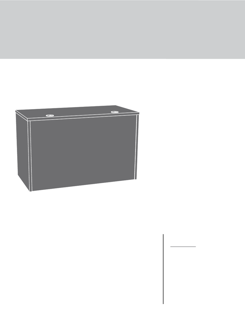
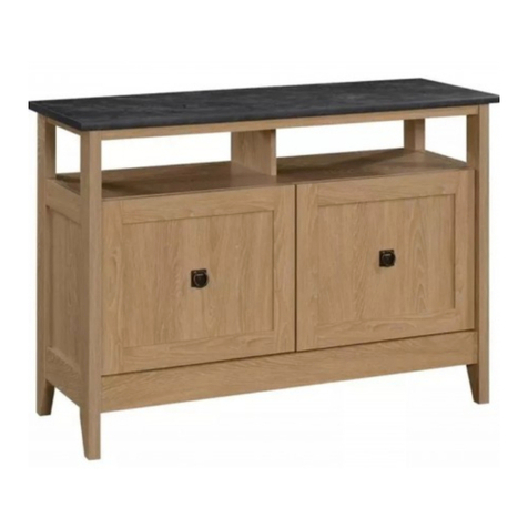
TV Stand
Barrister Home | Model 5417772
Your holder for all
things awesome.
Teknik
www.teknikoffice.co.uk
Table of Contents Assembly Tools Required
Part Identification
Hardware Identification
Assembly Steps
Français
Español
Safety
Warranty
Hammer
Not actual size
No. 2 Phillips Screwdriver
Tip Shown Actual Size
Skip the power trip.
This time.
3
4
5-21
22-24
25-28
29-30
31
WARNING
!
70 lbs.
70 lbs.
15"
15"
47-1/2"
47-1/2"
Use of a TV that is too heavy or large is hazardous. A TV that is too heavy will create a risk of a tip-over that can cause severe injury or
death. A TV that is too large for the available space might be accidentally pushed or bumped o the furniture, or subject to tip-over.
• Check the size and weight of your TV. Compare it to the diagram below – before you begin assembly!
• This Sauder unit is designed for use with televisions weighing less than 70 pounds. Never use with a TV that weighs more.
• The size of the television, front-to-back and side-to-side, must fit within the space defined in the diagram.
• Never place the front edge of the TV past the front edge of the TV support shelf (or stop molding – if equipped)
• Never allow the sides of the TV to extend past the side edges of the TV support surface.
• If the TV has a CRT picture tube, the picture tube cone may extend past the rear of the support shelf.
• Be sure to apply the warning label as instructed in the last assembly step. The label provides important safety related information.
Page 2
Part Identification
åWhile not all parts are labeled, some of the parts will have a label or an inked letter on the edge
to help distinguish similar parts from each other. Use this part identification to help identify similar parts.
Now you know
our ABCs.
A RIGHT END (1)
B LEFT END (1)
C RIGHT UPRIGHT (1)
D LEFT UPRIGHT (1)
E2 TOP (1)
F BOTTOM (1)
G BACK (1)
H DOOR (2)
I ADJUSTABLE SHELF (1)
J SMALL ADJUSTABLE SHELF (2)
K FRONT LEG (2)
L BACK LEG (2)
M TOP MOLDING (1)
N BOTTOM MOLDING (1)
O2 STOP MOLDING (1)
Page 3
A
B
C
D
E2
F
G
H
I
J
K
L
M
N
O2
J
K
L
H
Hardware Identification
Page 4
åScrews are shown actual size. You may receive extra hardware with your unit.
(Refer to Step 18 for proper
location and application)
WARNING LABEL - 1
2L
WARNING
Never use this furniture with a TV that is too
large or too heavy. Severe injury or death
can occur. The TV and furniture will be
unstable and may tip.
-The TV must less than 70 lbs.
-The base of the TV must be able to sit
completely on this shelf.
-Refer to instruction book for complete
safety information.
Note: This is a permanent label. Do not try
to remove. Surface will be damaged.
02/ 02 269224
ADJUSTABLE FOOT - 1
25E
FOOT BASE - 1
24E
GOLD 1" MACHINE SCREW - 2
50S
ANGLE BRACKET - 4
27G
BLACK 9/16" LARGE HEAD SCREW - 8
1S
BLACK 1-7/8" FLAT HEAD SCREW - 4
2S
BLACK 2-1/4" FLAT HEAD SCREW - 6
26S
RUBBER
SLEEVE - 12
2R
METAL PIN - 12
1R
SILVER 5/8" FLAT HEAD SCREW - 4
23S
BLACK 1/2" FLAT HEAD SCREW - 8
11S
TACK GLIDE - 4
13E
CAM SCREW - 6
8F
NAIL - 44
1N
HIDDEN CAM - 18
1F CAM DOWEL - 12
2F
KNOB - 2
69K
29M BUMPER CARD - 2
CONNECTOR SCREW - 4
8S
HIDDEN
CONNECTOR - 4
9F 14H HINGE - 4
Step 1
å Assemble your unit on a carpeted floor or on the empty
carton to avoid scratching your unit or the floor.
å Using your hammer, carefully tap four HIDDEN
CONNECTORS (9F) with SCREWS into the TOP (E2).
Step 2
å Insert a CONNECTOR SCREW (8S) into each
HIDDEN CONNECTOR (9F).
8S
9F
9F
E2
Page 5
Scan this QR code or go to this address:
http://qr.sauder.com/?ID=2278
to watch a video on how to assemble your unit.
Step 3
Page 6
å Push twelve HIDDEN CAMS (1F) into the ENDS (A and B),
UPRIGHTS (C and D), and BOTTOM (F). Then, insert the
metal end of a CAM DOWEL (2F) into each HIDDEN CAM.
å NOTE: Use the exact holes shown.
(12 used)
Arrow
1F
2F
Insert the metal end of the CAM
DOWEL into the HIDDEN CAM.
Arrow
Do not tighten the HIDDEN CAMS in this step.
A
B
C
D
F
Just think. The sooner
you do this, the sooner
you do something else.
å Push six HIDDEN CAMS (1F) into the ENDS (A and B).
Step 4
Page 7
A
B
Arrow
The arrow in the HIDDEN
CAM must point toward the
hole in the edge of the board.
Hole
1F
Arrow
Arrow
1F
(6 used)
Step 5
å Turn six CAM SCREWS (8F) into the FRONT LEGS (K).
Page 8
8F (6 used)
K
K
Step 6
Page 9
Surface with HIDDEN CONNECTORS
å Fasten the STOP MOLDING (O2) to the TOP (E2). Tighten
four HIDDEN CONNECTORS.
E2
O2
The holes are closer
to this surface.
How to use the HIDDEN CONNECTOR
To fasten two parts together using the HIDDEN
CONNECTORS, insert your screwdriver, at an angle,
into the slot in the HIDDEN CONNECTOR. While
pushing the screw into the hole of the adjoining
part, turn the screwdriver clockwise to tighten.
Step 7
Page 10
1
2
å Fasten a FRONT LEG (K) to the RIGHT END (A). Tighten
three HIDDEN CAMS.
å Fasten a BACK LEG (L) to the RIGHT END (A). Use three
BLACK 2-1/4" FLAT HEAD SCREWS (26S).
A
K
L
Surface with
HIDDEN CAMS
BLACK 2-1/4" FLAT HEAD SCREW
(3 used in this step)
26S
These surfaces
should be even.
The LEGS will
overhang this edge.
Edge with
CAM DOWELS
Step 8
Page 11
å Fasten a FRONT LEG (K) to the LEFT END (B). Tighten
three HIDDEN CAMS.
å Fasten a BACK LEG (L) to the LEFT END (B). Use three
BLACK 2-1/4" FLAT HEAD SCREWS (26S).
B
K
L
Surface with
HIDDEN CAMS
BLACK 2-1/4" FLAT HEAD SCREW
(3 used in this step)
26S
These surfaces
should be even.
The LEGS will
overhang this edge.
Edge with
CAM DOWELS
Don't worry. It isn't
Rome. This can be built
in a day.
Step 9
Page 12
Start Tighten
Arrow
Minimum
190 degrees
Caution
Risk of damage or
injury. HIDDEN CAMS
must be completely
tightened. HIDDEN
CAMS that are not
completely tightened
may loosen, and parts
may separate. To
completely tighten:
Arrow
Maximum
210 degrees
B
K
O2
E2
Surface with
HIDDEN CONNECTORS
Surface
with
HIDDEN
CAMS
å Fasten the LEFT END (B) to the TOP (E2). Tighten two
HIDDEN CAMS.
Step 10
Page 13
å Fasten the UPRIGHTS (C and D) to the TOP (E2). Tighten
four HIDDEN CAMS.
E2
D
C
Surface with
HIDDEN CAMS
Surface without
HIDDEN CAMS
Arrow
Minimum
190 degrees
Maximum
210 degrees
Finished edge
Step 11
å Fasten the BOTTOM (F) to the LEFT END (B). Tighten two
HIDDEN CAMS.
å Fasten the BOTTOM (F) to the UPRIGHTS (C and D). Use
four BLACK 1-7/8" FLAT HEAD SCREWS (2S).
å Slide the BOTTOM MOLDING* (N) onto the notched edge
of the BOTTOM (F).
å *U.S. Patent No. 5,499,886
Notched edge
N
F
Surface with
HIDDEN CAMS
Arrow
Minimum
190 degrees
Maximum
210 degrees
BLACK 1-7/8" FLAT HEAD SCREW
(4 used in this step)
2S
B
D
C
Page 14
Slide the BOTTOM
MOLDING (N) onto
the notched edge.
The groove
is closer to
this edge.
Step
å Fasten the RIGHT END (A) to the TOP (E2) and BOTTOM (F).
Tighten four HIDDEN CAMS.
å Fasten four ANGLE BRACKETS (27G) to the TOP (E2). Use
four BLACK 9/16" LARGE HEAD SCREWS (1S).
å Fasten the TOP MOLDING (M) to the TOP (E2). Use four
BLACK 9/16" LARGE HEAD SCREWS (1S) through the ANGLE
BRACKETS on the TOP and into the TOP MOLDING.
å NOTE: There are no pre-drilled holes in the TOP MOLDING.
The SCREWS will tighten into the groove.
Step 12
Arrow
Minimum
190 degrees
Maximum
210 degrees
E2
F
A
K
Surface
without
HIDDEN
CAMS
M
BLACK 9/16" LARGE HEAD SCREW
(8 used in this step)
1S
Page 15
The groove
is closer to
this edge.
27G
(4 used)
StepStep 13
Page 16
å Fasten the FOOT BASE (24E) to the BOTTOM (F). Use four
SILVER 5/8" FLAT HEAD SCREWS (23S).
å Push the ADJUSTABLE FOOT (25E) into the FOOT BASE (24E).
å Turn the adjustable end of the ADJUSTABLE FOOT completely in.
Final adjustments will be made after the unit is standing upright.
å Using your hammer, carefully tap four TACK GLIDES (13E) into
the LEGS (K and L).
25E
24E
F
Turn completely in. 13E
L
L
K
K
If you're doing this to
help a friend, don't
leave without a bite.
13E
SILVER 5/8" FLAT HEAD SCREW
(4 used in this step)
23S
Step
Page 17
å Carefully turn your unit over onto its front edges. Unfold the
BACK (G) and lay it over your unit.
å Make the bottom edge of the BACK (G) even with the bottom
edge of the BOTTOM (F). Then, make equal margins along the
side edges of the BACK (G). Push on opposite corners of your
unit if needed to make it "square".
å Fasten the BACK (G) to your unit using the NAILS (1N).
å NOTE: Be sure to tap NAILS into the holes that line up over
the UPRIGHTS (C and D).
å NOTE: Perforations have been provided for access through the
BACK. Carefully cut out the holes needed.
Unfinished surface
These holes must line up over
the UPRIGHTS (C and D).
G
Step 14
NAIL
(44 used in this step)
1N
These large holes must be
closer to the bottom edge.
F
StepStep 15
Page 18
å Fasten two HINGES (14H) to each DOOR (H). Use eight
BLACK 1/2" FLAT HEAD SCREWS (11S).
14H
BLACK 1/2" FLAT HEAD SCREW
(8 used in this step)
11S
H
H
14H
Step
Page 19
Step 16
Pro Tip: Lift with your
legs. And, you know,
your arms.
å Carefully stand your unit upright.
å Position your unit in its final location. Turn the ADJUSTABLE FOOT (25E)
downward until it touches the floor.
å IMPORTANT: The ADJUSTABLE FOOT should not extend beyond the
bottom edges of the LEGS (K and L).
å Before fastening the DOOR to your unit, be sure the mounting screw is against
the stops as shown in the right diagram. If it isn't, loosen the mounting screw
to slide it against the stops. Then tighten the mounting screw.
å Fasten the DOOR (H) to the RIGHT END (A) as shown in the lower diagram.
Use the screws in the HINGES. You should start each SCREW a few turns
before completely tightening any of them.
å Fasten a KNOB (69K) to the DOOR (H). Use a GOLD 1" MACHINE SCREW (50S).
å Peel two BUMPERS from the BUMPER CARD (29M) and stick them on the
DOOR (H) where they will come into contact with the RIGHT UPRIGHT (C).
å Repeat this step for the other DOOR (H).
å See the next step for DOOR adjustments.
H
A
C
69K
29M
29M
GOLD 1" MACHINE SCREW
(2 used for the KNOBS)
50S
Turn the ADJUSTABLE FOOT
downward until it touches the floor.
25E
Floor
K
L
Mounting
screw
Stop
Hinge
StepStep 17
Page 20
å Refer to the enlarged diagram to identify the parts on
the HINGES.
å The DOORS may need some adjustments. Follow the text
below to make needed adjustments.
å DOOR ADJUSTMENTS:
To adjust the DOORS from side to side (horizontal), turn the
adjusting screw in or out.
å To adjust the DOORS up and down (vertical), loosen both
vertical adjustment screws. Move the DOORS up or down to the
desired location. Tighten the screws after making adjustments.
å To adjust the DOORS in or out (depth), loosen the mounting
screw one turn and move the DOORS in or out, as needed.
Tighten the mounting screw after making adjustments.
(vertical adjustment)
Adjusting screw (horizontal)
Mounting screw (depth)

Other Teknik Indoor Furnishing manuals

Teknik Barrister Home 5418891 User manual

Teknik

Teknik Barrister Home 5418891 User manual

Teknik Barrister Home L-Shaped Desk 5418270 User manual

Teknik

Teknik Barrister Home L-Shaped Desk 5418270 User manual

Teknik Clifton Place 5421116 User manual

Teknik

Teknik Clifton Place 5421116 User manual

Teknik Hudson 5425815 User manual

Teknik

Teknik Hudson 5425815 User manual

Teknik 5412885 User manual

Teknik

Teknik 5412885 User manual

Teknik Craft 5421416 User manual

Teknik

Teknik Craft 5421416 User manual

Teknik Louvre 5415109 User manual

Teknik

Teknik Louvre 5415109 User manual

Teknik Hudson Elm finish 5427457 User manual

Teknik

Teknik Hudson Elm finish 5427457 User manual

Teknik Boulevard Cafe Desk 5420701 User manual

Teknik

Teknik Boulevard Cafe Desk 5420701 User manual

Teknik Essentials L-Shaped Desk 5425092 User manual

Teknik

Teknik Essentials L-Shaped Desk 5425092 User manual

Teknik 5418269 User manual

Teknik

Teknik 5418269 User manual

Teknik Clifton Place 5421113 User manual

Teknik

Teknik Clifton Place 5421113 User manual

Teknik 5420173 User manual

Teknik

Teknik 5420173 User manual

Teknik Boulevard Cafe 5420667 User manual

Teknik

Teknik Boulevard Cafe 5420667 User manual

Teknik Boulevard Cafe 5420650 User manual

Teknik

Teknik Boulevard Cafe 5420650 User manual

Teknik 5427134 User manual

Teknik

Teknik 5427134 User manual

Teknik 5427427 User manual

Teknik

Teknik 5427427 User manual

Teknik 5422378 User manual

Teknik

Teknik 5422378 User manual

Teknik Mahattan View 5423446 User manual

Teknik

Teknik Mahattan View 5423446 User manual

Teknik 5427873 User manual

Teknik

Teknik 5427873 User manual

Teknik Elstree 5426908 User manual

Teknik

Teknik Elstree 5426908 User manual

Teknik Hudson 5425829 User manual

Teknik

Teknik Hudson 5425829 User manual

Teknik 5427429 User manual

Teknik

Teknik 5427429 User manual

Teknik Hideaway Cotswold 5430446 User manual

Teknik

Teknik Hideaway Cotswold 5430446 User manual

Popular Indoor Furnishing manuals by other brands

Steelcase 41-TSLP Assembly Directions

Steelcase

Steelcase 41-TSLP Assembly Directions

modway Exceed EEI-2992 manual

modway

modway Exceed EEI-2992 manual

Safavieh Furniture Riona FOX2539 quick start guide

Safavieh Furniture

Safavieh Furniture Riona FOX2539 quick start guide

POVISON SF02AG user manual

POVISON

POVISON SF02AG user manual

Crosswater Alo Furniture Range manual

Crosswater

Crosswater Alo Furniture Range manual

Williams-Sonoma TABOR KNOB Assembly instructions

Williams-Sonoma

Williams-Sonoma TABOR KNOB Assembly instructions

Winners Only GA172R Assembly instructions

Winners Only

Winners Only GA172R Assembly instructions

TREX TXA15 Assembly instructions

TREX

TREX TXA15 Assembly instructions

Alice's Home EVA IEVACHEST3D manual

Alice's Home

Alice's Home EVA IEVACHEST3D manual

Forte EZNT133 Assembling Instruction

Forte

Forte EZNT133 Assembling Instruction

HOME RETAIL GROUP Matrix Desk 619/1645 Assembly instructions

HOME RETAIL GROUP

HOME RETAIL GROUP Matrix Desk 619/1645 Assembly instructions

U-Line H-6314 Assembly

U-Line

U-Line H-6314 Assembly

VECELO KHD-JYX-CST07-BRN Assembly instructions

VECELO

VECELO KHD-JYX-CST07-BRN Assembly instructions

Tojo System 200 instructions

Tojo

Tojo System 200 instructions

rst brands Venetia OP-ALBS6-VEN Assembly instructions

rst brands

rst brands Venetia OP-ALBS6-VEN Assembly instructions

Article DAKO Assembly instructions

Article

Article DAKO Assembly instructions

Lightolier D01 specification

Lightolier

Lightolier D01 specification

Bellamy Marylou quick start guide

Bellamy

Bellamy Marylou quick start guide

manuals.online logo
manuals.online logoBrands
  • About & Mission
  • Contact us
  • Privacy Policy
  • Terms and Conditions

Copyright 2025 Manuals.Online. All Rights Reserved.