manuals.online logo
Brands
  1. Home
  2. •
  3. Brands
  4. •
  5. Teknik
  6. •
  7. Indoor Furnishing
  8. •
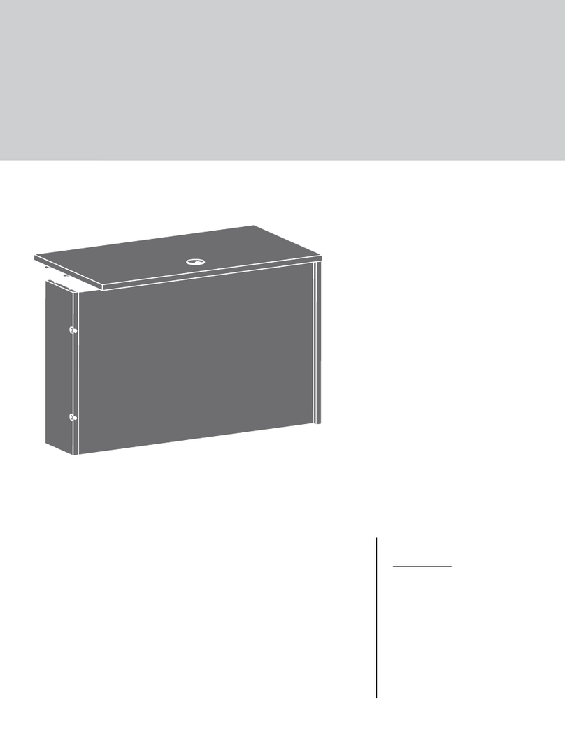
  9. Teknik 5420649 User manual

Teknik 5420649 User manual

www.teknikoffice.co.uk
It stands. You sit.
A thing of beauty,
this one.
Industrial Styled Sideboard
Boulevard Cafe Collection | Model 5420649
Teknik
Table of Contents Assembly Tools Required
Part Identification
Hardware Identification
Assembly Steps
Français
Español
Safety
Warranty
No. 2 Phillips Screwdriver
Tip Shown Actual Size
WARNING
!
Use of a TV that is too heavy or large is hazardous. A TV that is too heavy will create a risk of a tip-over that can cause severe injury or
death. A TV that is too large for the available space might be accidentally pushed or bumped o the furniture, or subject to tip-over.
• Check the size and weight of your TV. Compare it to the diagram below – before you begin assembly!
• This Sauder unit is designed for use with televisions weighing less than 70 pounds. Never use with a TV that weighs more.
• The size of the television, front-to-back and side-to-side, must fit within the space defined in the diagram.
• Never place the front edge of the TV past the front edge of the TV support shelf (or stop molding – if equipped)
• Never allow the sides of the TV to extend past the side edges of the TV support surface.
• If the TV has a CRT picture tube, the picture tube cone may extend past the rear of the support shelf.
• Be sure to apply the warning label as instructed in the last assembly step. The label provides important safety related information.
3
4
5-20
21-24
25-28
29-30
31
Skip the power trip.
This time.
70 lbs.
70 lbs.
20"
20"
70-1/8"
70-1/8"
Page 2
Part Identification
åWhile not all parts are labeled, some of the parts will have a label or an inked letter on the edge
to help distinguish similar parts from each other. Use this part identification to help identify similar parts.
Now you know
our ABCs.
A RIGHT END (1)
B LEFT END (1)
C UPRIGHT (1)
D TOP (1)
E REAR TOP TUBE (1)
F FRONT TOP TUBE (1)
G BACK (1)
H ADJUSTABLE SHELF (2)
I UPRIGHT TUBE (1)
J REAR BOTTOM TUBE (1)
K BOTTOM (1)
L FRONT BOTTOM TUBE (1)
M FOOT (2)
N FOOT BRACE (8)
O LEFT DOOR (2)
P RIGHT DOOR (2)
A
B
C
D
E
F
G
H
H
J
I
K
L
N
N
N
N
NN
N
N
M
M
OO
PP
Page 3
Hardware Identification
åScrews are shown actual size. You may receive extra hardware with your unit.
LARGE CAM
SCREW - 2
2
HIDDEN CAM - 6
1WOOD
DOWEL - 4
4
SMALL CAM
SCREW - 4
3
GROMMET
WITH CAP - 2
6
BLACK 1-3/8" HEX HEAD SCREW - 8
13
BLACK 5/8" PAN HEAD SCREW - 8
14 BLACK 1/2" HEX HEAD SCREW - 20
15
BLACK 1/2" PAN HEAD SCREW - 28
17
BLACK 1/2" MACHINE SCREW - 16
16
MAGNETIC CATCH - 4
10
METAL PIN - 8
7RUBBER SLEEVE - 8
8
L-WRENCH - 1
9
APPLIQUE CARD - 1
5
BLACK 2-1/4" PAN HEAD SCREW - 6
12
(Refer to the last step for proper location and application)
WARNING LABEL - 1
11
522,68 22,68
70 lbs. 31,75 kg 31,75 kg
Page 4
Step 1
å Assemble your unit on a carpeted floor or on the empty
carton to avoid scratching your unit or the floor.
å Fasten the TOP TUBES (E and F) to the TOP (D). Use
twelve BLACK 1/2" PAN HEAD SCREWS (17).
BLACK 1/2" FLAT HEAD SCREW
(12 used in this step)
17
D
E
F
These holes must be here.
The TUBE should cover
the long edge of the TOP.
The TUBE should cover
the long edge of the TOP.
These edges must be even.
This block must be here.
The tabs
should face
each other.
Page 5
å Fasten two MAGNETIC CATCHES (10) to the TOP (D).
Use four BLACK 5/8" PAN HEAD SCREWS (14).
å Turn two LARGE CAM SCREWS (2) into the TOP (D).
å Turn four SMALL CAM SCREWS (3) into the REAR TOP
TUBE (E).
Step 2
10
BLACK 5/8" PAN HEAD SCREW
(4 used for the MAGNETIC CATHCHES)
14
DE
3
2
Page 6
å Push six HIDDEN CAMS (1) into the BACK (G)
and UPRIGHT (C).
å Insert two GROMMETS WITH CAPS (6) into the BACK (G).
Step 3
The arrow in the HIDDEN
CAM must point toward the
hole in the edge of the board.
Hole
Arrow
Arrow
1
G
6
C
Page 7
Some assembly
(and snacks) required.
å Fasten the BACK (G) to the TOP REAR TUBE (E). Tighten
four HIDDEN CAMS.
Step 4
G
E
Surface with
HIDDEN CAMS
1
2
Page 8
å Fasten the UPRIGHT TUBE (I) to the UPRIGHT (C). Use
four BLACK 1/2" PAN HEAD SCREWS (17).
å NOTE: Two screws will turn into each surface of the
UPRIGHT (C). Be sure to use the exact holes shown.
Step 5
BLACK 1/2" FLAT HEAD SCREW
(4 used in this step)
17
C
IThese edges must be even.
Page 9
å Push two WOOD DOWELS (4) into the TOP (D).
å Fasten the UPRIGHT (C) to the TOP (D). Tighten two
HIDDEN CAMS.
å NOTE: Be sure the WOOD DOWELS in the TOP insert
into the holes in the UPRIGHT.
Step 6
1
2
4
Surface with
HIDDEN CAMS
D
G
C
Page 10
å Fasten the BOTTOM TUBES (J and L) to the BOTTOM (K).
Use twelve BLACK 1/2" PAN HEAD SCREWS (17).
Step 7
J
L
K
BLACK 1/2" FLAT HEAD SCREW
(12 used in this step)
17
The TUBE should cover
the long edge of the TOP.
The TUBE should cover
the long edge of the TOP.
These edges must be even.
Edge with more holes
Edge with holes
Surface with more holes
The tabs
should face
each other.
Page 11
Now might be a
good time to refresh
your drink.
Two MAGNETIC CATCH holes
will be located on the opposite
surface near this edge.
å Flip the BOTTOM (K) over.
å Push two WOOD DOWELS (4) into the BOTTOM (K).
å
Fasten two MAGNETIC CATCHES (10) to the BOTTOM (K).
Use four BLACK 5/8" PAN HEAD SCREWS (14).
Step 8
10
BLACK 5/8" PAN HEAD SCREW
(4 used for the MAGNETIC CATHCHES)
14
4
K
Page 12
å Flip the BOTTOM (K) over and fasten it to the BACK (G) and
UPRIGHT (C). Use six BLACK 2-1/4" PAN HEAD SCREWS (12).
å NOTE: Be sure the WOOD DOWELS in the BOTTOM insert
into the holes in the UPRIGHT.
Step 9
BLACK 2-1/4"" PAN HEAD SCREW
(6 used in this step)
12
K
G
C
Surface without
WOOD DOWELS
Page 13
J
å
Fasten the ENDS (A and B) to the ends of the TUBES (E, F, J,
and L).
Tighten eight BLACK 1-3/8" HEX HEAD SCREWS (13)
using the L-WRENCH (9).
Step 10
9
BLACK 1-3/8" ALLEN HEAD SCREW
13
BLACK 1-3/8" ALLEN HEAD SCREW
(8 used in this step)
13
A
B
J
L
E
F
Surface with
holes
Surface
without
holes
Page 14
å Fasten the FEET (M) to the BOTTOM TUBES (J and L).
Tighten four BLACK 1/2" HEX HEAD SCREWS (15) using
the L-WRENCH (9).
Step 11
9
J
L
M
M
BLACK 1/2" FLAT HEAD SCREW
(4 used in this step)
15
Page 15
å Fasten four FOOT BRACES (N) to the FEET (M) and
BOTTOM TUBES (J and L). Tighten eight BLACK 1/2"
HEX HEAD SCREWS (15) with the L-WRENCH (9).
å Fasten the remaining four FOOT BRACES (N) to the
ENDS (A and B) and BOTTOM TUBES (J and L). Tighten
eight BLACK 1/2" HEX HEAD SCREWS (15) with the
L-WRENCH (9).
å NOTE: Start each screw a few turns before tightening any
of the them.
Step 12
A
B
J
L
N
N
N
N
N
N
N
N
BLACK 1/2" FLAT HEAD SCREW
(16 used in this step)
15
M
M
9
Page 16
å Carefully stand your unit upright.
å Push the RUBBER SLEEVES (8) over the METAL
PINS (7). Insert the METAL PINS into the hole locations of
your choice in the ENDS (A and B) and UPRIGHT (C). Set
the ADJUSTABLE SHELVES (H) onto the METAL PINS.
Step 13
A
B
7
8
C
H
H
Page 17
Pro Tip: Lift with your
legs. And, you know,
your arms.
(8 used)
å Fasten the RIGHT DOORS (P) to the RIGHT END (A) and
UPRIGHT (C). Use eight BLACK 1/2" MACHINE SCREWS (16).
Step 14
BLACK 1/2" MACHINE SCREW
(8 used in this step)
16
A
C
P
P
Page 18
å Fasten the LEFT DOORS (O) to the LEFT END (B) and
UPRIGHT (C). Use eight BLACK 1/2" MACHINE SCREWS (16).
å To vertically adjust the DOORS (O and P), loosen the screws in
the hinges and make adjustments. Then, tighten the screws.
Step 15
BLACK 1/2" MACHINE SCREW
(8 used in this step)
16
O
P
P
O
Page 19
B
C
Step 16
å Peel APPLIQUES from the APPLIQUE CARD (5) and stick them onto each visible HIDDEN CAM.
å Apply the WARNING LABEL (11) to the TOP (D). You should be able to read the label when the TV is removed
from the unit. When the TV is in place, it should hide the label. Peel o the backing and apply the label as shown
in the diagram.
å NOTE: This is a permanent label intended to last for the life of the product. Once applied, do not try to remove it.
å NOTE: Please read the back pages of the instruction booklet for important safety information.
å This completes assembly. Clean with your favorite furniture polish or a damp cloth. Wipe dry.
522,68 22,68
70 lbs. 31,75 kg 31,75 kg
522,68 22,68
70 lbs. 31,75 kg 31,75 kg
11
D
70 lbs.
35 lbs.
35 lbs.
50 lbs. total
Page 20
5
To cover HIDDEN CAMS
(6 used)

Other Teknik Indoor Furnishing manuals

Teknik 5418793 User manual

Teknik

Teknik 5418793 User manual

Teknik Hudson 5425825 User manual

Teknik

Teknik Hudson 5425825 User manual

Teknik 5427030 User manual

Teknik

Teknik 5427030 User manual

Teknik 5420173 User manual

Teknik

Teknik 5420173 User manual
Teknik Hudson 5427871 User manual

Teknik

Teknik Hudson 5427871 User manual

Teknik Barrister Home Lift Up 5420329 User manual

Teknik

Teknik Barrister Home Lift Up 5420329 User manual

Teknik Barrister Home L-Shaped Desk 5418270 User manual

Teknik

Teknik Barrister Home L-Shaped Desk 5418270 User manual

Teknik Essentials L-Shaped Desk 5425092 User manual

Teknik

Teknik Essentials L-Shaped Desk 5425092 User manual

Teknik Hudson Elm finish 5427457 User manual

Teknik

Teknik Hudson Elm finish 5427457 User manual

Teknik 5418072 User manual

Teknik

Teknik 5418072 User manual

Teknik 5420276 User manual

Teknik

Teknik 5420276 User manual

Teknik Home Study 5426055 User manual

Teknik

Teknik Home Study 5426055 User manual

Teknik 5420277 User manual

Teknik

Teknik 5420277 User manual

Teknik Shaker Style 5428225 User manual
Teknik

Teknik Shaker Style 5428225 User manual

Teknik White Home Study L-Shaped Desk User manual

Teknik

Teknik White Home Study L-Shaped Desk User manual

Teknik 5414142 User manual

Teknik

Teknik 5414142 User manual

Teknik Streamline L-Shaped Desk 5414417 User manual

Teknik

Teknik Streamline L-Shaped Desk 5414417 User manual

Teknik Metro 5426461 User manual

Teknik

Teknik Metro 5426461 User manual

Teknik Wide Bookcase 5420282 User manual

Teknik

Teknik Wide Bookcase 5420282 User manual

Teknik Lux Desk 5426429 User manual

Teknik

Teknik Lux Desk 5426429 User manual

Teknik 5425655 User manual

Teknik

Teknik 5425655 User manual

Teknik City Centre 5427120 User manual

Teknik

Teknik City Centre 5427120 User manual

Teknik Clifton Place 5421116 User manual

Teknik

Teknik Clifton Place 5421116 User manual

Teknik Canal Heights 5419231 User manual

Teknik

Teknik Canal Heights 5419231 User manual

Popular Indoor Furnishing manuals by other brands

Coaster 130071 Assembly instructions

Coaster

Coaster 130071 Assembly instructions

JSI Moto installation instructions

JSI

JSI Moto installation instructions

RTA Products Techni Mobili RTA-2024 Assembly instructions

RTA Products

RTA Products Techni Mobili RTA-2024 Assembly instructions

nardi CLIP 70 manual

nardi

nardi CLIP 70 manual

Noble House Home Furnishings Dining Chair Assembly instructions

Noble House Home Furnishings

Noble House Home Furnishings Dining Chair Assembly instructions

Hublot HUB-MEUEV-10 instructions

Hublot

Hublot HUB-MEUEV-10 instructions

Safavieh Furniture DSK5712 quick start guide

Safavieh Furniture

Safavieh Furniture DSK5712 quick start guide

Canyon 98-161 Assembly instructions

Canyon

Canyon 98-161 Assembly instructions

Forte Hoyvik HVKL2162 Assembling Instruction

Forte

Forte Hoyvik HVKL2162 Assembling Instruction

Twin-Star International Classic Flame 26MMS9616 manual

Twin-Star International

Twin-Star International Classic Flame 26MMS9616 manual

MAJA Möbel System 1704 Assembling instructions

MAJA Möbel

MAJA Möbel System 1704 Assembling instructions

Maintal Mirco zerl Assembly instructions

Maintal

Maintal Mirco zerl Assembly instructions

Emmezeta TUZK231B Assembling Instruction

Emmezeta

Emmezeta TUZK231B Assembling Instruction

Martha Stewart BELDEN CASTERED Assembly instructions

Martha Stewart

Martha Stewart BELDEN CASTERED Assembly instructions

Lightolier Lighting Systems LSC-10 Specification sheet

Lightolier

Lightolier Lighting Systems LSC-10 Specification sheet

fantastic furniture STOCKHOLM Assembly instructions

fantastic furniture

fantastic furniture STOCKHOLM Assembly instructions

Allen + Roth Roveland 2026VA-30-201-900-SR manual

Allen + Roth

Allen + Roth Roveland 2026VA-30-201-900-SR manual

Amisco Bridget Upholstered Dining Chair 30575 Assembly

Amisco

Amisco Bridget Upholstered Dining Chair 30575 Assembly

manuals.online logo
manuals.online logoBrands
  • About & Mission
  • Contact us
  • Privacy Policy
  • Terms and Conditions

Copyright 2025 Manuals.Online. All Rights Reserved.