manuals.online logo
Brands
  1. Home
  2. •
  3. Brands
  4. •
  5. Teknik
  6. •
  7. Indoor Furnishing
  8. •
  9. Teknik 5425015 User manual

Teknik 5425015 User manual

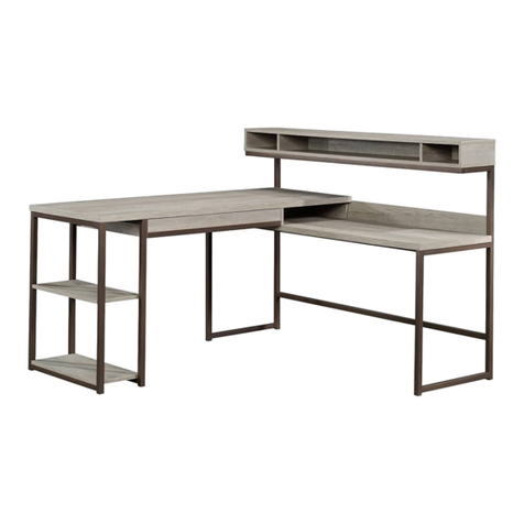
Summit Desk
Model 5425015
The original desktop.
Teknik
www.teknikoffice.co.uk
Table of Contents Assembly Tools Required
Part Identification
Hardware Identification
Assembly Steps
Français
Español
Safety
Warranty
Hammer
Not actual size
No. 2 Phillips Screwdriver
Tip Shown Actual Size
3
4-5
6-28
29-32
33-36
37-38
39
Page 2
Part Identification
åWhile not all parts are labeled, some of the parts will have a label or an inked letter on the edge
to help distinguish similar parts from each other. Use this part identification to help identify similar parts.
Now you know
our ABCs.
A RIGHT END (1)
B LEFT END (1)
B51 PENCIL DRAWER BOTTOM (1)
C MODESTY PANEL (1)
D UPRIGHT (1)
D14 FILE RIGHT DRAWER SIDE (1)
D15 FILE LEFT DRAWER SIDE (1)
D78 FILE DRAWER BACK (1)
D266 PENCIL RIGHT DRAWER SIDE (1)
D267 PENCIL LEFT DRAWER SIDE (1)
D540 PENCIL DRAWER BACK (1)
D541 PENCIL DRAWER BOX FRONT (1)
D716 FILE DRAWER BOTTOM (1)
E BOTTOM (1)
F FILE DRAWER FRONT (1)
G LEFT BRACE (1)
H LEFT BOTTOM MOLDING (1)
J FRONT/BACK MOLDING (2)
K LONG BRACE (1)
LPEDESTAL LEFT FRONT/RIGHT
REAR LEG (2)
M BACK (1)
N BRACE (1)
O PENCIL DRAWER FRONT (1)
PPEDESTAL RIGHT FRONT/LEFT
REAR LEG (2)
Q DESK LEFT FRONT LEG (1)
R DESK LEFT REAR LEG (1)
S RIGHT BOTTOM MOLDING (1)
T TOP (1)
Page 3
D15
D540
A
B
C
D
E
F
G
HJ
KL
M
N
O
P
Q
R
S
T
D541
D716
D14
D78
D267
D266
B51
J
P
L
Hardware Identification
åScrews are shown actual size. You may receive extra hardware with your unit.
FILE GLIDE - 2
4B
35GA CABINET RIGHT - 1 35GB CABINET LEFT - 1 35GC DRAWER RIGHT - 1 35GD DRAWER LEFT - 1
(EXTENSION SET SHOWN SEPARATED)
EXTENSION RAIL - 2
35MA EXTENSION SLIDE - 2
35MC 10A SLIDE CAM - 2
Page 4
HIDDEN CAM - 38
1F CAM DOWEL - 20
2F CAM SCREW - 18
8F WOOD DOWEL - 11
15F
CROSS SLOTTED DOWEL - 2
24F EXTENSION BRACKET - 2
43G PULL - 1
35K
GROMMET CAP - 1
1P GROMMET - 1
10P CAM COVER - 6
75P
GLUE - 1
177M
Hardware Identification
åScrews are shown actual size. You may receive extra hardware with your unit.
Page 5
BLACK 9/16" LARGE HEAD SCREW - 4
1S 3S GOLD 5/16" FLAT HEAD SCREW - 16
BLACK 7/8" LARGE HEAD SCREW - 4
17S 30S BLACK 1-9/16" FLAT HEAD SCREW - 8
BLACK 7/8" MACHINE SCREW - 2
37S BLACK 2-3/8" FLAT HEAD BOLT - 2
103S
BLACK 1-15/16" FLAT HEAD SCREW - 2
113S
Step 1
Page 6
å Assemble your unit on a carpeted floor or on the empty carton to
avoid scratching your unit or the floor.
å Push twenty HIDDEN CAMS (1F) into the ENDS (A and B),
MODESTY PANEL (C), UPRIGHT (D), BOTTOM (E), BACK (M), and
BRACE (N). Then, insert the metal end of a CAM DOWEL (2F) into
each HIDDEN CAM.
A
B
C
D
E
M
N
Insert the metal end of the CAM
DOWEL into the HIDDEN CAM.
Arrow
Do not tighten the HIDDEN CAMS in this step.
Insert the metal end of the CAM
DOWEL into the HIDDEN CAM.
The arrow in the HIDDEN
CAM must point toward the
hole in the edge of the board.
Hole
Arrow
1F
2F
(20 used)
Metal end
å Push eighteen HIDDEN CAMS (1F) into the remaining
holes of the ENDS (A and B), UPRIGHT (D), LEFT
BRACE (G), and BOTTOM MOLDINGS (H and S).
Step 2
Page 7
A
B
D
G
H
S
Arrow
The arrow in the HIDDEN
CAM must point toward the
hole in the edge of the board.
Hole
1F
(18 used)
Arrow
1F
Arrow
å Turn eighteen CAM SCREWS (8F) into the LEGS (L, P, Q, and R).
å First, fill the hole in the end of the LEG (Q) 1/4 to 1/2 full with
GLUE (177M). Then, insert the WOOD DOWEL (15F) into the hole.
Wipe away the excess GLUE.
Step 3
Page 8
L
P
Q
R
P
L
8F
(18 used)
Inspect the parts thoroughly before
assembling. Disassembly of glued
parts is extremely dicult.
Caution
!
15F
177M
Fill the holes 1/4 to 1/2 full with GLUE.
å First, fill the holes in the LEGS (Q and R) 1/4 to 1/2 full with
GLUE (177M). Then, insert the WOOD DOWELS (15F) into
the holes. Wipe away the excess GLUE.
å Now, fill the holes in the LEFT END (B) and LEFT BRACE (G)
1/4 to 1/2 full with GLUE.
å Fasten the LEGS (Q and R) to the LEFT END (B) and LEFT
BRACE (G). Tighten six HIDDEN CAMS. Wipe away the
excess GLUE.
å NOTE: Be sure the WOOD DOWELS in the LEGS insert into
the LEFT END and LEFT BRACE.
Step 4
Page 9
B
G
Q
R
Inspect the parts thoroughly before
assembling. Disassembly of glued
parts is extremely dicult.
Caution
!
15F
1
2
Surface
with
HIDDEN
CAMS
These surfaces
should be even.
Edge with
CAM DOWELS
15F
Surface
with
HIDDEN
CAMS
177M
Fill the holes 1/4 to 1/2 full with GLUE.
å Fasten the LEGS (L and P) to the RIGHT END (A)
and RIGHT BOTTOM MOLDING (S). Tighten six
HIDDEN CAMS.
å NOTE: Position the RIGHT BOTTOM MOLDING (S)
exactly as shown.
Step 5
Page 10
A
P
S
L
Surface
with
HIDDEN
CAMS
These surfaces
should be even.
Edge with
CAM DOWELS
Surface
with
HIDDEN
CAMS
The holes are
closer to this edge.
å Fasten the LEGS (L and P) to the UPRIGHT (D) and LEFT
BOTTOM MOLDING (H). Tighten six HIDDEN CAMS.
å NOTE: Position the LEFT BOTTOM MOLDING (H) exactly
as shown.
Step 6
Page 11
D
H
L
P
Surface
with
HIDDEN
CAMS
These surfaces
should be even.
Edge with
CAM DOWELS
Surface
with
HIDDEN
CAMS
This hole
must be here.
Step 7
Page 12
A
D
Open end
å Separate the EXTENSION SLIDES (35MC) from the EXTENSION RAILS (35MA) as
shown in the upper diagram below. Be prepared, the parts are greasy.
å Fasten the EXTENSION RAILS (35MA) to the RIGHT END (A) and UPRIGHT (D). Use
four GOLD 5/16" FLAT HEAD SCREWS (3S) through holes #1 and #3..
å NOTE: For each EXTENSION RAIL, turn a SCREW into the hole shown in the enlarged
diagram. Then, slide the inner cartridge of the EXTENSION RAIL in to find the other hole
that lines up with the hole in the END/UPRIGHT. Turn a SCREW into this hole.
å NOTE: The EXTENSION SLIDES (35MC) will be used later for the FILE DRAWER.
Open end
Push the black lever in and pull the SLIDE from the RAIL.
35MA
35MC
3
2
1
1
2
3
GOLD 5/16" FLAT HEAD SCREW
(4 used for the RAILS)
3S
These holes
must be here.
These holes
must be here.
å Carefully flip the UPRIGHT (D) over.
å Fasten two EXTENSION BRACKETS (43G) to the UPRIGHT (D). Use four
BLACK 9/16" LARGE HEAD SCREWS (1S).
å Fasten the CABINET RIGHT (35GA) to the EXTENSION BRACKETS (43G)
on the UPRIGHT (D). Use two GOLD 5/16" FLAT HEAD SCREWS (3S)
through holes #1 and #3.
å NOTE: Use the exact holes shown in the EXTENSION BRACKETS.
å Fasten the CABINET LEFT (35GB) to the LEFT END (B). Use two GOLD
5/16" FLAT HEAD SCREWS (3S) through holes #1 and #3.
Step 8
Page 13
B
D
1
2
3
1
2
3
Roller end
Roller end
GOLD 5/16" FLAT HEAD SCREW
(4 used for the RAILS)
3S
BLACK 9/16" LARGE HEAD SCREW
(4 used for the BRACKETS)
1S
43G
å Fasten the MODESTY PANEL (C) to the
LEFT END (B). Tighten two HIDDEN CAMS.
Step 9
Page 14
Start Tighten
Arrow
Minimum
190 degrees
Caution
Risk of damage or
injury. HIDDEN CAMS
must be completely
tightened. HIDDEN
CAMS that are not
completely tightened
may loosen, and parts
may separate. To
completely tighten:
Arrow
Maximum
210 degrees
C
Surface
with
HIDDEN
CAMS
B
Roller end
å First, fill the hole in the TOP (T) 1/4 to 1/2 full with GLUE (177M).
å Then, fasten the LEFT END (B) and MODESTY PANEL (C) to
the TOP (T). Tighten four HIDDEN CAMS.
å NOTE: Be sure the WOOD DOWEL in the LEG (Q) inserts into
the TOP. Wipe away the excess GLUE.
Step 10
425015www.sauder.com/service Page 15
Arrow
Minimum
190 degrees
Maximum
210 degrees
C
B
T
Inspect the parts thoroughly before
assembling. Disassembly of glued
parts is extremely dicult.
Caution
!
Q
Meet Part (T). This component has
been engineered to be lighter, stronger,
faster… well ok. Not technically faster.
But definitely makes for a sturdier
Desk that’s easier to assemble and
friendlier to the environment.
The large hole
must be here.
177M
Fill the holes 1/4 to 1/2 full with GLUE.
å Push two CROSS-SLOTTED DOWELS (24F) into the LONG BRACE (K)
as shown.
å NOTE: The threads in the DOWEL should be pointed toward the hole in
the edge of the LONG BRACE.
å First, fill the holes in the ends of the LONG BRACE (K) 1/4 to 1/2 full
with GLUE (177M). Then, insert the WOOD DOWELS (15F) into the
holes. Wipe away the excess GLUE.
å Now, fill the hole in the LEFT BRACE (G) 1/4 to 1/2 full with GLUE.
å Fasten the LONG BRACE (K) to the LEFT BRACE (G). Use one BLACK
2-3/8" FLAT HEAD BOLT (103S).
å NOTE: The BOLT will thread into the DOWEL in the LONG BRACE.
å NOTE: Be sure the WOOD DOWEL in the LONG BRACE inserts into the
LEFT BRACE. Wipe away the excess GLUE.
Step 11
Page 16
24F
The long slot should face up
and be parallel to the long
edges of the SIDE SKIRTS.
KK
Inspect the parts thoroughly before
assembling. Disassembly of glued
parts is extremely dicult.
Caution
!
15F
G
103S
BLACK 2-3/8" FLAT HEAD BOLT
(1 used for the LONG BRACE)
Surface with slotted dowels
177M
Fill the holes 1/4 to 1/2 full with GLUE.
å First, fill the hole in the LEFT BOTTOM MOLDING (H) 1/4 to 1/2
full with GLUE.
å Next, fasten the UPRIGHT (D) to the TOP (T). Tighten two
HIDDEN CAMS.
å NOTE: Be sure the WOOD DOWEL in the LONG BRACE (K)
inserts into the LEFT BOTTOM MOLDING (H). Wipe away the
excess GLUE.
å Fasten the LEFT BOTTOM MOLDING (H) to the LONG BRACE (K).
Use one BLACK 2-3/8" FLAT HEAD BOLT (103S).
å Fasten the UPRIGHT (D) to the MODESTY PANEL (C). Use two
BLACK 1-15/16" FLAT HEAD SCREWS (113S).
Step 12
Page 17
Arrow
Minimum
190 degrees
Maximum
210 degrees
103S
BLACK 2-3/8" FLAT HEAD BOLT
(1 used for the LONG BRACE)
Inspect the parts thoroughly before
assembling. Disassembly of glued
parts is extremely dicult.
Caution
!
K
T
D
H
C
BLACK 1-15/16" FLAT HEAD SCREW
(2 used for the MODESTY PANEL)
113S
103S
177M
Fill the holes 1/4 to 1/2 full with GLUE.
å First, fill the holes in the BRACE (N) 1/4 to 1/2 full with
GLUE (177M). Then, insert the WOOD DOWELS (15F)
into the holes. Wipe away the excess GLUE.
å Now, fill the hole in the UPRIGHT (D) 1/4 to 1/2 full
with GLUE.
å Fasten the BRACE (N) to the UPRIGHT (D). Tighten
one HIDDEN CAM.
å NOTE: Be sure the WOOD DOWEL in the BRACE
inserts into the UPRIGHT. Wipe away the excess GLUE.
å Insert the CAM DOWELS in the edge of the BACK (M)
into the UPRIGHT (D) but do not tighten them.
Step 13
Page 18
Arrow
Minimum
190 degrees
Maximum
210 degrees
MN
Inspect the parts thoroughly before
assembling. Disassembly of glued
parts is extremely dicult.
Caution
!
15F
Surface with
HIDDEN CAMS
Surface
with
HIDDEN
CAMS
Finished edge
D
15F
NOTE: Do not
tighten in this step.
Finished
edge
177M
Fill the holes 1/4 to 1/2 full with GLUE.
å Slide the FRONT/BACK MOLDINGS* (J) onto the
notched edges of the BOTTOM (E).
å Fasten the BOTTOM (E) to the LEFT BOTTOM
MOLDING (H). Tighten two HIDDEN CAMS.
å *U.S. Patent No. 5,499,886
Step 14
Page 19
Arrow
Minimum
190 degrees
Maximum
210 degrees
Notched edge
Notched edge
These surfaces
should be even.
E
J
J
Surface with
HIDDEN CAMS
H
E
The groove
is closer to
this edge.
The groove
is closer to
this edge.
Surface with
HIDDEN CAMS
å First, fill the hole in the RIGHT END (A) 1/4 to 1/2 full
with GLUE.
å Next, fasten the RIGHT END (A) to the BOTTOM (E),
BACK (M), BRACE (N), and TOP (T). Tighten seven
HIDDEN CAMS.
å NOTE: You may need to lift the BACK (M) up
slightlyto align the holes.
å NOTE: Be sure the WOOD DOWEL in the BRACE (N)
inserts into the RIGHT END (A). Wipe away the
excess GLUE.
å Fasten the BACK (M) to the UPRIGHT (D). Tighten
two HIDDEN CAMS.
Step 15
Page 20
Arrow
Minimum
190 degrees
Maximum
210 degrees
Inspect the parts thoroughly before
assembling. Disassembly of glued
parts is extremely dicult.
Caution
!
T
A
MN
E
D
S
NOTE: Tighten two HIDDEN
CAMS to fasten the BACK (M)
to the UPRIGHT (D).
177M
Fill the holes 1/4 to 1/2 full with GLUE.

Other Teknik Indoor Furnishing manuals

Teknik Elstree Executive Desk 5426918 User manual

Teknik

Teknik Elstree Executive Desk 5426918 User manual

Teknik Clifton Place 5421115 User manual

Teknik

Teknik Clifton Place 5421115 User manual

Teknik Hampstead 5426504 User manual

Teknik

Teknik Hampstead 5426504 User manual

Teknik Barrister Home 5418891 User manual

Teknik

Teknik Barrister Home 5418891 User manual

Teknik Denver Swivel Recliner User manual

Teknik

Teknik Denver Swivel Recliner User manual

Teknik 5431916 User manual

Teknik

Teknik 5431916 User manual

Teknik 5427415 User manual

Teknik

Teknik 5427415 User manual

Teknik CUBE RECEPTION CHAIR MODULAR UNIT User manual

Teknik

Teknik CUBE RECEPTION CHAIR MODULAR UNIT User manual

Teknik Boulevard Cafe 5420650 User manual

Teknik

Teknik Boulevard Cafe 5420650 User manual

Teknik Barrister Home 5420176 User manual

Teknik

Teknik Barrister Home 5420176 User manual

Teknik 5427127 User manual

Teknik

Teknik 5427127 User manual

Teknik Hudson Elm finish 5427457 User manual

Teknik

Teknik Hudson Elm finish 5427457 User manual

Teknik 5427872 User manual

Teknik

Teknik 5427872 User manual

Teknik 5418072 User manual

Teknik

Teknik 5418072 User manual

Teknik 5414873 User manual

Teknik

Teknik 5414873 User manual

Teknik 5423023 User manual

Teknik

Teknik 5423023 User manual

Teknik Boulevard Cafe 5427345 User manual

Teknik

Teknik Boulevard Cafe 5427345 User manual

Teknik Contemporary Bureau 5416966 User manual

Teknik

Teknik Contemporary Bureau 5416966 User manual

Teknik Hudson 5425825 User manual

Teknik

Teknik Hudson 5425825 User manual

Teknik Boulevard Cafe Series User manual

Teknik

Teknik Boulevard Cafe Series User manual

Teknik 5412320 User manual

Teknik

Teknik 5412320 User manual

Teknik City Centre 5425653 User manual

Teknik

Teknik City Centre 5425653 User manual

Teknik 5424933 User manual

Teknik

Teknik 5424933 User manual

Teknik City Centre 5426059 User manual

Teknik

Teknik City Centre 5426059 User manual

Popular Indoor Furnishing manuals by other brands

TikkTokk Nanny Panel Playpen Assembly guide

TikkTokk

TikkTokk Nanny Panel Playpen Assembly guide

Möbelix MDIK211R Assembling Instruction

Möbelix

Möbelix MDIK211R Assembling Instruction

URBAN OUTFITTERS Ezra Side Table Assembly instructions

URBAN OUTFITTERS

URBAN OUTFITTERS Ezra Side Table Assembly instructions

Simpli Home WyndenHall Brooklyn + Max AXCKIT17-GR manual

Simpli Home

Simpli Home WyndenHall Brooklyn + Max AXCKIT17-GR manual

WIEMANN Lissabon 991798 Assembly instructions

WIEMANN

WIEMANN Lissabon 991798 Assembly instructions

Happy Babies HAPPY RW01 Assembly instructions

Happy Babies

Happy Babies HAPPY RW01 Assembly instructions

Furniture of America CM7556D Assembly instructions

Furniture of America

Furniture of America CM7556D Assembly instructions

Furniture of America CM5233 Assembly instructions

Furniture of America

Furniture of America CM5233 Assembly instructions

VONDOM Faz 54166T Assembling instructions

VONDOM

VONDOM Faz 54166T Assembling instructions

Furniture of America CM-BK1032-WH Assembly instructions

Furniture of America

Furniture of America CM-BK1032-WH Assembly instructions

Bertolini R-620 BE Assembly instructions

Bertolini

Bertolini R-620 BE Assembly instructions

John Lewis Glass Shelf user manual

John Lewis

John Lewis Glass Shelf user manual

LDI Spaces SAFCO Diaz 5009 Assembly instructions

LDI Spaces

LDI Spaces SAFCO Diaz 5009 Assembly instructions

Early Childhood Resources ELR-0625 manual

Early Childhood Resources

Early Childhood Resources ELR-0625 manual

Coaster 723458 Assembly instructions

Coaster

Coaster 723458 Assembly instructions

Bravo 254150 quick start guide

Bravo

Bravo 254150 quick start guide

Schardt Zirbe 06 263 Assembly instructions

Schardt

Schardt Zirbe 06 263 Assembly instructions

Naomi Home Deluxe Glider and Ottoman quick start guide

Naomi Home

Naomi Home Deluxe Glider and Ottoman quick start guide

manuals.online logo
manuals.online logoBrands
  • About & Mission
  • Contact us
  • Privacy Policy
  • Terms and Conditions

Copyright 2025 Manuals.Online. All Rights Reserved.