manuals.online logo
Brands
  1. Home
  2. •
  3. Brands
  4. •
  5. Teknik
  6. •
  7. Indoor Furnishing
  8. •
  9. Teknik 5427873 User manual

Teknik 5427873 User manual

NOTE: THIS INSTRUCTION
BOOKLET CONTAINS
IMPORTANT SAFETY
INFORMATION.
PLEASE READ AND KEEP
FOR FUTURE REFERENCE.
10/13/21 Lot # 572777
Purchased:
__________________
English pg 1-28
Français pg 29-32
Español pg 33-36
3-Drawer Mobile
Pedestal
Hudson Elm finish | Model 5427873
Teknik
www.teknikoffice.co.uk
Table of Contents Assembly Tools Required
Part Identification
Hardware Identification
Hardware Usage Guide
Assembly Steps
Français
Español
Safety
Warranty
Hammer
Not actual size
No. 2 Phillips Screwdriver
Tip Shown Actual Size
3
4-5
7
6-28
29-32
33-36
37-38
39
Pae 2
Adjustable Wrench
Part Identification
åWhile not all parts are labeled, some of the parts will have a label or an inked letter on the edge
to help distinguish similar parts from each other. Use this part identification to help identify similar parts.
Now you know
our ABCs.
A RIGHT END (1)
B LEFT END (1)
C TOP (1)
D BACK (1)
D78 LARGE DRAWER BACK (1)
D109 DRAWER BACK (2)
D579 RIGHT DRAWER SIDE (2)
D580 LEFT DRAWER SIDE (2)
D581 LARGE RIGHT DRAWER SIDE (1)
D582 LARGE LEFT DRAWER SIDE (1)
D707 LARGE DRAWER BOTTOM (1)
D716 DRAWER BOTTOM (2)
E BOTTOM (1)
F BASE (1)
G DRAWER FRONT (2)
H LOCKING DRAWER FRONT (1)
Pae 3
A
B
C
D
E
FH
D78 D581
D707
D582
G
D579
D716
D580
D109
Hardware Identification
åScrews are shown actual size. You may receive extra hardware with your unit.
(EXTENSION SET SHOWN SEPARATED)
EXTENSION
SLIDE - 2
40MC
EXTENSION
RAIL - 2
40MA 10A SLIDE
CAM - 6 8B FILE
ROD - 2
15B FILE
GLIDE - 2 8CN NON-SWIVEL
CASTER - 2 8CS SWIVEL
CASTER - 2 42F WOOD DOWEL - 16
40CA CABINET RIGHT - 2 40CB CABINET LEFT - 2 40CC DRAWER RIGHT - 2 40CD DRAWER LEFT - 2
4G METAL
BRACKET - 4 34G INTERLOCK
MECHANISM - 1 62G DRAWER
ACTUATOR - 2 76G L - LOCK
BRACKET - 1
Pae 4
Hardware Identification
åScrews are shown actual size. You may receive extra hardware with your unit.
77G Z - LOCK
BRACKET - 1 21J LOCK PACK - 1 202K PULL - 3 10M TOUCH-UP PEN - 1
1S BLACK 9/16" LARGE HEAD SCREW - 28 3S GOLD 5/16" FLAT HEAD SCREW - 24
37S BLACK 7/8" MACHINE SCREW - 6 51S BLACK 9/16" PAN HEAD SCREW - 3
30S BLACK 1-9/16" FLAT HEAD SCREW - 12
11S BLACK 1/2" FLAT HEAD SCREW - 6
Pae 5
Hardware Usae Guide
1. Insert the dowel end of the FASTENER into the
hole of the adjoinin part.
NOTE: The dowel end of the FASTENER must
remain fully inserted in the hole of the adjoinin
part while lockin the FASTENER.
2. Tihten the FASTENER with a Phillips
screwdriver as tiht as possible.
Dowel end
2.
Push a TWIST-LOCK® FASTENER
into the lare hole in the part.
1.
HOW TO USE A TWIST-LOCK®FASTENER
Pae 6
å Assemble your unit on a carpeted floor or on the empty
carton to avoid scratchin your unit or the floor.
å Insert two WOOD DOWELS (42F) into the BACK (D).
å NOTE: You may need to ently tap the WOOD DOWEL in
with your hammer.
å Fasten the BOTTOM (E) to the BACK (D). Tihten one
TWIST-LOCK® FASTENER.
å NOTE: Be sure the WOOD DOWELS in the BACK insert
into the BOTTOM.
Step 1
D
E
Surface with
TWIST-LOCK®
FASTENERS
Surface with
TWIST-LOCK®
FASTENERS
Pae 7
Some assembly
(and snacks) required.
42F
42F
Step 2
å Fasten two CABINET RIGHTS (40CA) to the
RIGHT END (A). Use four GOLD 5/16" FLAT HEAD
SCREWS (3S) throuh holes #1 and #3.
Pae 8
These holes
must be here.
1
2
3
4
A
GOLD 5/16" FLAT HEAD SCREW
(4 used in this step)
3S Roller end
Ede with
TWIST-LOCK®
FASTENERS
1
2
3
4
Step 3
Pae 9
å Separate the EXTENSION SLIDES (40MC) from the EXTENSION RAILS (40MA) as shown in the upper diaram below. Be
prepared, the parts are reasy.
å Fasten one EXTENSION RAIL (40MA) to the RIGHT END (A). Use two GOLD 5/16" FLAT HEAD SCREWS (3S) throuh
holes #1 and #4.
å NOTE: For each EXTENSION RAIL, turn a SCREW into the hole shown in the enlared diaram. Then, slide the inner cartride
of the EXTENSION RAIL in to find the other hole that lines up with the hole in the END. Turn a SCREW into this hole.
å NOTE: The EXTENSION SLIDES will be used later for the LARGE DRAWER.
Push the black lever in and pull the SLIDE from the RAIL.
40MA40MC
A
1
2
3
4
Open end
GOLD 5/16" FLAT HEAD SCREW
(2 used in this step)
3S
Step 4
å Fasten the INTERLOCK MECHANISM (34G) to the RIGHT END (A).
Use three BLACK 9/16" PAN HEAD SCREWS (51S).
å Fasten the L-LOCK BRACKET (76G) to the RIGHT END (A) exactly
as shown. Use two BLACK 9/16" LARGE HEAD SCREWS (1S).
Pae 10
BLACK 9/16" LARGE HEAD SCREW
(2 used for the BRACKET)
1S
A
34G
76G
BLACK 9/16" PAN HEAD SCREW
(3 used for the MECHANISM)
51S
å Insert four WOOD DOWELS (42F) into the
RIGHT END (A).
å NOTE: You may need to ently tap the WOOD DOWEL
in with your hammer.
å Fasten the BACK (D) and BOTTOM (E) to the RIGHT
END (A). Tihten four TWIST-LOCK® FASTENERS.
å NOTE: Be sure the WOOD DOWELS in the END and
insert into the BACK and BOTTOM.
Step 5
Pae 11
A
D
E
42F
(4 used)
Step 6
Pae 12
1
2
3
4
å Fasten two CABINET LEFTS (40CB) to the LEFT END (B).
Use four GOLD 5/16" FLAT HEAD SCREWS (3S) throuh
holes #1 and #3.
Roller end
B
Ede with
TWIST-LOCK®
FASTENERS 1
2
3
4
GOLD 5/16" FLAT HEAD SCREW
(4 used in this step)
3S
Step 7
Pae 13
B
3
2
1
4
GOLD 5/16" FLAT HEAD SCREW
(2 used in this step)
3S
å Fasten the remainin EXTENSION RAIL (40MA) to the LEFT
END (B). Use two GOLD 5/16" FLAT HEAD SCREWS (3S)
throuh holes #1 and #4.
å NOTE: For each EXTENSION RAIL, turn a SCREW into the
hole shown in the enlared diaram. Then, slide the inner
cartride of the EXTENSION RAIL in to find the other hole that
lines up with the hole in the END. Turn a SCREW into this hole.
Open end
Step 8
Pae 14
B
D
E
å Insert four WOOD DOWELS (42F) into
the LEFT END (B).
å NOTE: You may need to ently tap the WOOD DOWEL
in with your hammer.
å Fasten the LEFT END (B) to the BACK (D) and
BOTTOM (E). Tihten four TWIST-LOCK® FASTENERS.
å NOTE: Be sure the WOOD DOWELS in the BACK and
BOTTOM insert into the END.
42F
(4 used)
Step 9
å Insert six WOOD DOWELS (42F) into the TOP (C).
å NOTE: You may need to ently tap the WOOD DOWEL in
with your hammer.
å Fasten the ENDS (A and B) and BACK (D) to the
ENDS (A and B). Tihten five TWIST-LOCK® FASTENERS.
å NOTE: Be sure the WOOD DOWELS in the TOP insert into
the ENDS and BACK.
Pae 15
A
D
B
C
Just think. The sooner
you do this, the sooner
you do somethin else.
42F
42F
(6 used)
Step 10
Pae 16
å Fasten four METAL BRACKETS (4G) to the
ENDS (A and B) and BOTTOM (E). Use four
BLACK 9/16" LARGE HEAD SCREWS (1S).
å NOTE: Be sure the BRACKETS are even with the edes of
the ENDS and BOTTOM.
å Fasten the BASE (F) to the METAL BRACKETS on the
ENDS and BOTTOM. Use four BLACK 9/16" LARGE
HEAD SCREWS (1S).
4G
BLACK 9/16" LARGE HEAD SCREW
(8 used in this step)
1S
4G
4G
A
B
E
F
Ede with
wrapped seam
Step 11
å Fasten the CASTERS (8CN and 8CS) to the BOTTOM (E)
exactly as shown. Use sixteen BLACK 9/16" LARGE
HEAD SCREWS (1S).
Pae 17
BLACK 9/16" LARGE HEAD SCREW
(16 used in this step)
1S
E
8CN
8CS
The small tab
should be here.
Step 12
Pae 18
BLACK 9/16" LARGE HEAD SCREW
(2 used in this step)
1S
G
77G
With the palm of
your hand, tap
the DRAWER
BOTTOM down
into the roove.
The tabs should insert freely
into the slots. Gently tilt the
DRAWER SIDES side to side
until the tabs slip into the slots.
Groove
Be sure the DRAWER
BOTTOM inserts into the
DRAWER FRONT roove.
G
D716
D716
Unfinished
surface
D580
D579
D580
D579
G
D580
D579
D109
å Fasten the Z-LOCK BRACKET (77G) to one of the
DRAWER FRONTS (G). Use two BLACK 9/16" LARGE
HEAD SCREWS (1S).
å Insert the DRAWER SIDES (D579 and D580) at an anle
into the slot at each end of the DRAWER FRONT (G).
å Slide the DRAWER BOTTOM (D716) into the rooves
in the DRAWER SIDES (D579 and D580) and
DRAWER FRONT (G).
å Fasten the DRAWER BACK (D109) to the DRAWER
SIDES (D579 and D580). Use four BLACK 1-9/16" FLAT
HEAD SCREWS (30S).
å NOTE: Be sure the DRAWER BOTTOM (D716) inserts
into the roove of the DRAWER BACK (D109).
å Repeat this step for the remaining small DRAWER.
12
34
Be sure the
DRAWER
BOTTOM
inserts into
the DRAWER
BACK roove.
30S
Start each screw a few turns before
completely tihtenin any of them.
BLACK 1-9/16" FLAT HEAD SCREW
(8 used in this step)
Step 13
Pae 19
å Insert a SLIDE CAM (10A) into each DRAWER SIDE (D579 and D580).
å Fasten the DRAWER RIGHT (40CC) to the RIGHT DRAWER SIDE (D579)
and the DRAWER LEFT (40CD) to the LEFT DRAWER SIDE (D580). Use
four GOLD 5/16" FLAT HEAD SCREWS (3S) throuh holes #2 and #4.
å NOTE: The screw head in the CAM must be visible throuh the slotted
hole in the SLIDE.
å Repeat this step for the remainin small DRAWER.
GOLD 5/16" FLAT HEAD SCREW
(8 used in this step)
3S Drawer Slide
Center the screw in the oval hole.
10A
Screw head - turn CAM to line up holes in
the SLIDES with holes in DRAWER SIDES
10A
Roller end
Roller end
1
2
3
4
1
2
3
4
D580
D579
Step 14
Pae 20
With the palm of
your hand, tap
the DRAWER
BOTTOM down
into the roove.
å Fasten the LARGE DRAWER BACK (D78) to the LARGE DRAWER SIDES (D581 and D582). Use four
BLACK 1-9/16" FLAT HEAD SCREWS (30S).
å NOTE: Be sure the DRAWER BOTTOM (D707) inserts into the roove of the DRAWER BACK (D78).
1 2
3
å Insert the LARGE DRAWER SIDES (D581 and D582)
at an anle into the slot at each end of the LOCKING
DRAWER FRONT (H).
å Slide the LARGE DRAWER BOTTOM (D707) into the
rooves in the LARGE DRAWER SIDES (D581 and D582)
and LOCKING DRAWER FRONT (H).
The tabs should insert freely
into the slots. Gently tilt the
DRAWER SIDES side to side
until the tabs slip into the slots.
Groove
30S
Start each screw a few turns before
completely tihtenin any of them.
BLACK 1-9/16" FLAT HEAD SCREW
(4 used in this step)
Be sure the DRAWER
BOTTOM inserts into the
DRAWER FRONT roove.
H
D707
D707
D78
Unfinished
surface
Be sure the
DRAWER
BOTTOM
inserts into
the DRAWER
BACK roove.
D582
D581 D582
D581
H
D582
D581

Other Teknik Indoor Furnishing manuals
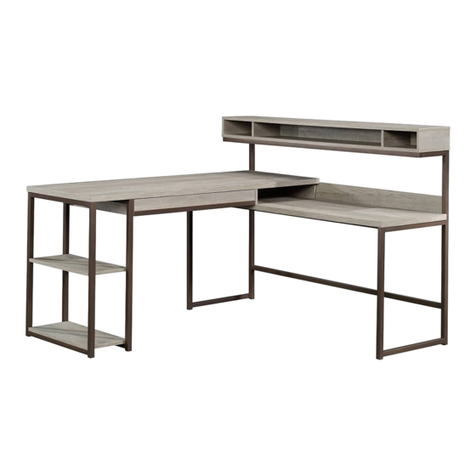
Teknik Canal Heights Console 5419230 User manual

Teknik

Teknik Canal Heights Console 5419230 User manual

Teknik 5426436 User manual

Teknik

Teknik 5426436 User manual

Teknik 5418793 User manual

Teknik

Teknik 5418793 User manual

Teknik 5431916 User manual

Teknik

Teknik 5431916 User manual

Teknik 5424152 User manual

Teknik

Teknik 5424152 User manual

Teknik Hampstead Park  Narrow Bookcase 5420283 User manual

Teknik

Teknik Hampstead Park Narrow Bookcase 5420283 User manual

Teknik Canyon Lane 5425306 User manual

Teknik

Teknik Canyon Lane 5425306 User manual

Teknik 5426463 User manual

Teknik

Teknik 5426463 User manual

Teknik 5402174 User manual

Teknik

Teknik 5402174 User manual

Teknik 5426510 User manual

Teknik

Teknik 5426510 User manual

Teknik 5420277 User manual

Teknik

Teknik 5420277 User manual

Teknik Hampstead Park 5420834 User manual

Teknik

Teknik Hampstead Park 5420834 User manual

Teknik Canal Heights 5419228 User manual

Teknik

Teknik Canal Heights 5419228 User manual

Teknik Boulevard Cafe 5420667 User manual

Teknik

Teknik Boulevard Cafe 5420667 User manual

Teknik 5426133 User manual

Teknik

Teknik 5426133 User manual

Teknik 5427427 User manual

Teknik

Teknik 5427427 User manual

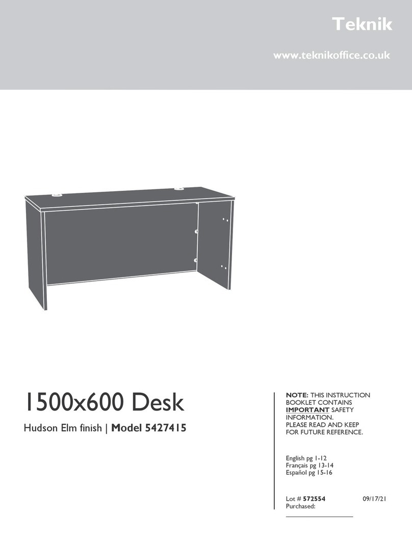
Teknik Wide Bookcase 5420282 User manual
Teknik

Teknik Wide Bookcase 5420282 User manual

Teknik Home Study 5426055 User manual

Teknik

Teknik Home Study 5426055 User manual

Teknik 5424933 User manual

Teknik

Teknik 5424933 User manual

Teknik 5417593 User manual

Teknik

Teknik 5417593 User manual

Teknik City Centre 5427120 User manual

Teknik

Teknik City Centre 5427120 User manual

Teknik White Home Study L-Shaped Desk User manual

Teknik

Teknik White Home Study L-Shaped Desk User manual

Teknik 5427413 User manual

Teknik

Teknik 5427413 User manual

Teknik Trestle 5410421 User manual

Teknik

Teknik Trestle 5410421 User manual

Popular Indoor Furnishing manuals by other brands

RUSTA CATANIA 605011450102 manual

RUSTA

RUSTA CATANIA 605011450102 manual

Vela Tango 300 user manual

Vela

Vela Tango 300 user manual

Furniture of America CM4910S Assembly instructions

Furniture of America

Furniture of America CM4910S Assembly instructions

MAISONS DU MONDE GUAM 198367 manual

MAISONS DU MONDE

MAISONS DU MONDE GUAM 198367 manual

Habitat Pegase 822402 manual

Habitat

Habitat Pegase 822402 manual

Prosedia Younico PRO Assembly and operating instructions

Prosedia

Prosedia Younico PRO Assembly and operating instructions

Made Monterosso AX8 Quick start quide

Made

Made Monterosso AX8 Quick start quide

Modus Furniture International TOWNSEND STORAGE BED Assembly instructions

Modus Furniture International

Modus Furniture International TOWNSEND STORAGE BED Assembly instructions

Biohort Shelves Assembly manual

Biohort

Biohort Shelves Assembly manual

Sauder Barrister Lane 414720 manual

Sauder

Sauder Barrister Lane 414720 manual

Office Boffins MAC001 Assembly instructions

Office Boffins

Office Boffins MAC001 Assembly instructions

VIPACK jaxx RKST1114 Assembly instructions

VIPACK

VIPACK jaxx RKST1114 Assembly instructions

Forever Redwood MAYNARD MODERN REDWOOD PATIO TABLE Assembly instructions

Forever Redwood

Forever Redwood MAYNARD MODERN REDWOOD PATIO TABLE Assembly instructions

Burgtec STRATA 360 troubleshooting manual

Burgtec

Burgtec STRATA 360 troubleshooting manual

Manhattan Comfort Beekman 17.51 Assembly instructions

Manhattan Comfort

Manhattan Comfort Beekman 17.51 Assembly instructions

King Living Oscar Sofa Bed Assembly instructions

King Living

King Living Oscar Sofa Bed Assembly instructions

Mocka Dahlia Four Drawer Assembly instructions

Mocka

Mocka Dahlia Four Drawer Assembly instructions

Balmani Idra Basin Cabinet installation guide

Balmani

Balmani Idra Basin Cabinet installation guide

manuals.online logo
manuals.online logoBrands
  • About & Mission
  • Contact us
  • Privacy Policy
  • Terms and Conditions

Copyright 2025 Manuals.Online. All Rights Reserved.