manuals.online logo
Brands
  1. Home
  2. •
  3. Brands
  4. •
  5. Teknik
  6. •
  7. Indoor Furnishing
  8. •
  9. Teknik Boutique Style Desk User manual

Teknik Boutique Style Desk User manual

www.teknikoffice.co.uk
The original desktop.
NOTE: THIS INSTRUCTION
BOOKLET CONTAINS IMPORTANT
SAFETY INFORMATION.
PLEASE READ AND KEEP FOR
FUTURE REFERENCE.
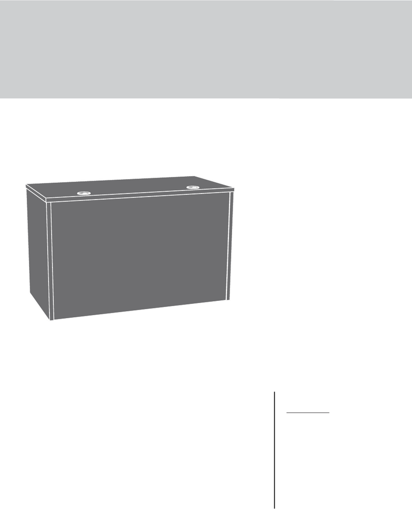
Boutique Style Desk
Model 5420194
Teknik
Table of Contents Assembly Tools Required
Part Identification
Hardware Identification
Assembly Steps
Hammer
Not actual size
No. 2 Phillips Screwdriver
Tip Shown Actual Size
Skip the power trip.
This time.
2-3
4
5-22
Part Identification
A RIGHT END (1)
B LEFT END (1)
C RIGHT UPRIGHT (1)
D LEFT UPRIGHT (1)
D16 RIGHT DRAWER SIDE (2)
D17 LEFT DRAWER SIDE (2)
D144 DRAWER BACK (2)
D950 DRAWER BOTTOM (2)
E MODESTY PANEL (1)
F TOP (1)
G BOTTOM (2)
H BACK (2)
I LEFT UPPER DOOR PANEL (1)
J LEFT CENTER DOOR PANEL (1)
K LEFT LOWER DOOR PANEL (1)
L RIGHT UPPER DOOR PANEL (1)
M RIGHT CENTER DOOR PANEL (1)
N RIGHT LOWER DOOR PANEL (1)
O ADJUSTABLE SHELF (2)
P VALANCE (1)
Q BRACE (2)
R SKIRT (2)
S RIGHT DRAWER FRONT (1)
T LEFT DRAWER FRONT (1)
U DOOR MOLDING (4)
Page 2
åWhile not all parts are labeled, some of the parts will have a label or an inked letter on the edge
to help distinguish similar parts from each other. Use this part identification to help identify similar parts.
Now you know
our ABCs.
Part Identification
A
B
C
D
E
F
G
G
HH
O
O
P
Q
Q
R
R
D16
D17
D950
D144
D16
D17
D950
D144
L
M
N
T
S
I
J
K
U
U
U
U
Page 3
Hardware Identification
åScrews are shown actual size. You may receive extra hardware with your unit.
METAL BRACKET - 6
4G
BLACK 9/16" LARGE HEAD SCREW - 12
1S
36P CAM COVER - 8
12S BROWN 1" FLAT HEAD SCREW - 16
SCREW COVER - 12
16P
3S GOLD 5/16" FLAT HEAD SCREW - 16
METAL PIN - 12
1R
10A SLIDE CAM - 4
BLACK 1/2" FLAT HEAD SCREW - 8
11S
48H HINGE
BRACKET - 4 HINGE - 4
54H DOOR STOP - 2
4I
NAIL - 40
1N
HIDDEN CAM - 28
1F CAM DOWEL - 20
2F BI-CAM DOWEL - 4
25F
GLUE - 1
54M RUBBER SLEEVE - 8
2R
BLACK 1-15/16" FLAT HEAD SCREW - 8
113S
30S BLACK 1-9/16" FLAT HEAD SCREW - 8
WOOD DOWEL - 8
30F
PULL - 8
132K
35GA CABINET RIGHT - 2 35GB CABINET LEFT - 2 35GC DRAWER RIGHT - 2 35GD DRAWER LEFT - 2
Page 4
Step 1
å Assemble your unit on a carpeted floor or on the empty
carton to avoid scratching your unit or the floor.
å Push twenty-eight HIDDEN CAMS (1F) into the
ENDS (A and B), UPRIGHTS (C and D), BOTTOMS (G),
DOOR PANELS (I, J, K, L, M, and N ) and BRACES (Q).
Then, insert the metal end of a CAM DOWEL (2F) into
each HIDDEN CAM except in the DOOR PANELS.
Page 5
Arrow
1F
2F
(28 used)
(20 used)
Arrow
1F
2F
Do not tighten the HIDDEN CAMS in this step.
Do not insert CAM
DOWELS (2F) into the DOOR
PANELS (I, J, K, L, M, and N).
Insert the metal end of the CAM
DOWEL into the HIDDEN CAM.
Arrow
I
J
K
L
M
N
G
G
D
C
A
B
Q
Q
Step 2
Page 6
å Fasten the CABINET RIGHTS (35GA) to the RIGHT END (A)
and LEFT UPRIGHT (D) and the CABINET LEFTS (35GB) to
the LEFT END (B) and RIGHT UPRIGHT (C). Use eight GOLD
5/16" FLAT HEAD SCREWS (3S) through holes #1 and #3.
1
1
2
2
3
3
Roller end
Roller end
Roller end
Roller end
GOLD 5/16" FLAT HEAD SCREW
(8 used in this step)
3S
D
C
A
B
1
1
2
2
3
3
Remember:
Righty tighty.
Lefty loosey.
å Fasten the ENDS (A and B) to the BOTTOMS (G). Tighten
four HIDDEN CAMS.
Step 3
Page 7
Start Tighten
Arrow
Minimum
190 degrees
Caution
Risk of damage or
injury. HIDDEN CAMS
must be completely
tightened. HIDDEN
CAMS that are not
completely tightened
may loosen, and parts
may separate. To
completely tighten:
Arrow
Maximum
210 degrees
A
B
G
G
Surface with
HIDDEN CAMS
Surface with
HIDDEN CAMS
Surface with holes
Surface without holes
These holes must be here.
Rounded edge
Rounded edge
å Insert four METAL PINS (1R) into the short edges of the
BRACES (Q).
å Fasten the BRACES (Q) to the ENDS (A and B). Tighten
two HIDDEN CAMS.
å NOTE: Be sure the PINS in the BRACES insert into the
holes in the ENDS.
Step 4
Page 8
1R
A
B
Surface with
HIDDEN CAMS
Surface with
HIDDEN CAMS
Q
Q
Arrow
Minimum
190 degrees
Maximum
210 degrees
Finished edge
Finished edge
å Fasten the UPRIGHTS (C and D) to the BRACES (Q) and
BOTTOMS (G). Tighten six HIDDEN CAMS.
å NOTE: Be sure the PINS in the BRACES insert into the
holes in the UPRIGHTS.
Step 5
Page 9
A
B
Q
Q
Arrow
Minimum
190 degrees
Maximum
210 degrees
C
D
Rounded edge
Rounded edge
G
G
å Fasten six METAL BRACKETS (4G) to the SKIRTS (R). Use
six BLACK 9/16" LARGE HEAD SCREWS (1S).
å Fasten the SKIRTS (R) to the ENDS (A and B), UPRIGHTS
(C and D), and BOTTOMS (G). Use six BLACK 9/16"
LARGE HEAD SCREWS (1S).
Step 6
Page 10
BLACK 9/16" LARGE HEAD SCREW
(12 used in this step)
1S
R
R
R
R
4G
4G
4G
A
B
C
D
G
G
å Fasten the VALANCE (P) and MODESTY PANEL (E) to
the UPRIGHTS (C and D). Use eight BLACK 1-15/16" FLAT
HEAD SCREWS (113S).
Step 7
Page 11
BLACK 1-15/16" FLAT HEAD SCREW
(8 used in this step)
113S
Finished edge
C
D
E
P
Curved edge
Finished surface
å Fasten the TOP (F) to the ENDS (A and B) and UPRIGHTS
(C and D). Tighten eight HIDDEN CAMS.
Step 8
Page 12
Surface with holes
F
These edges must be even.
Arrow
Minimum
190 degrees
Maximum
210 degrees
Don't worry. It isn't
Rome. This can be built
in a day.
A
B
C
D
Step 9
Page 13
å Carefully turn your unit over onto its front edges. Lay the
BACKS (H) over the two box openings.
å Make equal margins along all four edges of the BACKS (H).
å Fasten the BACKS (H) to your unit using the NAILS (1N).
Do not stand the unit upright without the
BACK fastened. The unit may collapse.
Caution
Finished surface Finished surface
NAIL
(40 used in this step)
1N
H
H
Step 10
Page 14
I
J
K
U
U
Fill the holes 1/4 to 1/2 full with GLUE.
Inspect the parts thoroughly before
assembling. Disassembly of glued
parts is extremely dicult.
Caution
!
54M
å 1. Fill the two outside holes in the LEFT UPPER DOOR PANEL (I) 1/4 to 1/2 full with
GLUE (54M).
å 2. Insert two WOOD DOWELS (30F) into the holes. Wipe away the excess GLUE.
Insert a BI-CAM DOWEL (25F) into the center hole of the LEFT UPPER DOOR
PANEL (I).
å 3. Place a MOLDING (U) over the WOOD DOWELS and the BI-CAM DOWEL in the
LEFT UPPER DOOR PANEL (I).
å 4. Fill the two outside holes in the long edge of the LEFT CENTER DOOR PANEL (J)
1/4 to 1/2 full with GLUE (54M). Then push the LEFT CENTER DOOR PANEL (J) onto
the WOOD DOWELS and the BI-CAM DOWEL.
Wipe away the excess GLUE.
å NOTE: It is important that you orient the picture on the CENTER PANEL as shown.
å Repeat this step to fasten the remaining MOLDING (U) and LEFT LOWER DOOR
PANEL (K).
30F
25F
25F
1st
2nd
2nd
2nd
3rd
4th
IMPORTANT
Follow the numerical assembly order. The center
hole in each DOOR PANEL will not get glue.
It is important that you
orient the picture on the
CENTER PANEL as shown.
Step 11
Page 15
L
M
N
U
U
Fill the holes 1/4 to 1/2 full with GLUE.
Inspect the parts thoroughly before
assembling. Disassembly of glued
parts is extremely dicult.
Caution
!
54M
å 1. Fill the two outside holes in the RIGHT UPPER DOOR PANEL (L) 1/4 to 1/2 full
with GLUE (54M).
å 2. Insert two WOOD DOWELS (30F) into the holes. Wipe away the excess GLUE.
Insert a BI-CAM DOWEL (25F) into the center hole of the RIGHT UPPER DOOR
PANEL (L)
å 3. Place a MOLDING (U) over the WOOD DOWELS and the BI-CAM DOWEL in the
RIGHT UPPER DOOR PANEL (L).
å 4. Fill the two outside holes in the long edge of the RIGHT CENTER DOOR PANEL (M)
1/4 to 1/2 full with GLUE (54M). Then push the RIGHT CENTER DOOR PANEL (M)
onto the WOOD DOWELS and the BI-CAM DOWEL.
Wipe away the excess GLUE.
å NOTE: It is important that you orient the picture on the CENTER PANEL as shown.
å Repeat this step to fasten the remaining MOLDING (U) and RIGHT LOWER DOOR
PANEL (N).
30F
25F
25F
1st
2nd
2nd
2nd
3rd
4th
IMPORTANT
Follow the numerical assembly order. The center
hole in each DOOR PANEL will not get glue.
It is important that you
orient the picture on the
CENTER PANEL as shown.
å Carefully flip the doors over. Tighten eight HIDDEN
CAMS. Wipe away the excess glue.
å First, slide a HINGE BRACKET (48H) into the L shaped
clip underneath the HINGE (54H). Second, swing the
other end of it up until it snaps into the HINGE as shown
in the right diagram. Repeat this for the remaining three
HINGE BRACKETS and HINGES.
å Fasten the HINGES (54H) to the DOORS PANELS (I, K, L,
and N). Use eight BLACK 1/2" FLAT HEAD SCREWS (11S).
Step 12
Page 16
54H
54H
54H
54H
54H
48H
1ST
2ND
Square hole
Arrow
Minimum
190 degrees
Maximum
210 degrees
I
K
L
N
BLACK 1/2" FLAT HEAD SCREW
(8 used in this step)
11S
å Carefully stand your unit upright.
å Fasten the LEFT DOOR PANELS (I and K) to the LEFT
END (B). Use the screws in the HINGES BRACKETS.
å Fasten three PULLS (132K) to the DOOR PANELS (I, J,
and K). Use six BROWN 1" FLAT HEAD SCREWS (12S).
å Push a DOOR STOP (4I) into the hole in the UPRIGHT (D)
as shown.
å Repeat this step fastening the RIGHT DOOR PANELS to the
RIGHT END (A) and DOOR STOP (4I) to the UPRIGHT (C).
å See the next step for DOOR adjustments.
Step 13
Page 17
BROWN 1" FLAT HEAD SCREW
(12 used for the PULLS)
12S
4I
132K
K
I
J
B
A
C
D
Step 14
Page 18
å Refer to the enlarged diagram to identify the parts on
the HINGES.
å The DOORS may need some adjustments. Follow the text
below to make needed adjustments.
å DOOR ADJUSTMENTS:
To adjust the DOORS from side to side (horizontal) turn the
adjusting screw in or out.
å To adjust the DOORS up and down (vertical), loosen both
vertical adjustment screws. Move the DOORS up or down to the
desired location. Tighten the screws after making adjustments.
å To adjust the DOORS in or out (depth), loosen the mounting
screw one turn and move the DOORS in or out, as needed.
Tighten the mounting screw after making adjustments.
Adjusting screw (horizontal)
Mounting screw (depth)
(vertical adjustment)
Step 15
Page 19
å Fasten the DRAWER BACK (D144) to the DRAWER SIDES (D16
and D17). Use four BLACK 1-9/16" FLAT HEAD SCREWS (30S).
å NOTE: Be sure the DRAWER BOTTOM (D950) inserts into
the groove of the DRAWER BACK (D144).
å Repeat this step for the remaining drawer.
12
3
å Insert the DRAWER SIDES (D16 and D17) at an angle
into the slot at each end of the DRAWER FRONT (S).
å Slide the DRAWER BOTTOM (D950) into the grooves in the
DRAWER SIDES (D16 and D17) and DRAWER FRONT (S).
The tabs should insert freely
into the slots. Gently tilt the
DRAWER SIDES side to side
until the tabs slip into the slots.
Groove
30S
Start each screw a few turns before
completely tightening any of them.
BLACK 1-9/16" FLAT HEAD SCREW
(8 used in this step)
Be sure the DRAWER
BOTTOM inserts into the
DRAWER FRONT groove.
D950
D950
D144
SS
Unfinished
surface
With the palm of your
hand, tap the DRAWER
BOTTOM down into
the groove.
Be sure the
DRAWER
BOTTOM
inserts into
the DRAWER
BACK groove.
D16
D16
D16
D17 D17
D17
Step 16
Page 20
å Insert a SLIDE CAM (10A) into the DRAWER
SIDES (D16 and D17).
å Fasten a DRAWER RIGHT (35GC) to the DRAWER RIGHT
SIDE (D16) and a DRAWER LEFT (35GD) to the DRAWER
LEFT SIDE (D17). Use four GOLD 5/16" FLAT HEAD
SCREWS (3S) through holes #1 and #3.
å NOTE: The screw head in the CAM must be visible
through the slotted hole in the SLIDE.
å Fasten a PULL (132K) to the DRAWER FRONT (S). Use
two BROWN 1" FLAT HEAD SCREWS (12S).
å Repeat this step for the remaining drawer.
1
2
3
1
2
3
Roller end
Roller end
GOLD 5/16" FLAT HEAD SCREW
(8 used in this step)
3S
(4 screws per drawer)
Screw head - turn CAM to line up holes in
the SLIDES with holes in DRAWER SIDES
10A
10A
BROWN 1" FLAT HEAD SCREW
(4 used in this step)
12S
D16
D17
S
132K

This manual suits for next models

1

Other Teknik Indoor Furnishing manuals
Teknik Hudson Elm finish 5427422 User manual

Teknik

Teknik Hudson Elm finish 5427422 User manual

Teknik 5427455 User manual

Teknik

Teknik 5427455 User manual

Teknik 5423505 User manual

Teknik

Teknik 5423505 User manual

Teknik 5418295 User manual

Teknik

Teknik 5418295 User manual

Teknik Home Study 5426616 User manual

Teknik

Teknik Home Study 5426616 User manual

Teknik Scribed Oak Storage Desk 5418294 User manual

Teknik

Teknik Scribed Oak Storage Desk 5418294 User manual

Teknik New Hyde 426440 User manual

Teknik

Teknik New Hyde 426440 User manual

Teknik Stationmaster 5426454 User manual

Teknik

Teknik Stationmaster 5426454 User manual

Teknik 5427415 User manual

Teknik

Teknik 5427415 User manual

Teknik Boulevard Cafe 5421950 User manual

Teknik

Teknik Boulevard Cafe 5421950 User manual

Teknik 5426135 User manual

Teknik

Teknik 5426135 User manual

Teknik 5420277 User manual

Teknik

Teknik 5420277 User manual

Teknik Hampstead Park Compact Desk 5420284 User manual
Teknik

Teknik Hampstead Park Compact Desk 5420284 User manual

Teknik Boulevard Cafe 5420650 User manual

Teknik

Teknik Boulevard Cafe 5420650 User manual

Teknik 5427134 User manual

Teknik

Teknik 5427134 User manual

Teknik Barrister 5420330 User manual

Teknik

Teknik Barrister 5420330 User manual
Teknik 5431262 User manual

Teknik

Teknik 5431262 User manual

Teknik Hudson 5425829 User manual

Teknik

Teknik Hudson 5425829 User manual

Teknik Denver Swivel Recliner User manual

Teknik

Teknik Denver Swivel Recliner User manual

Teknik 5420275 User manual

Teknik

Teknik 5420275 User manual

Teknik Barrister Home 5418902 User manual

Teknik

Teknik Barrister Home 5418902 User manual

Teknik Hythe 5426437 User manual

Teknik

Teknik Hythe 5426437 User manual

Teknik 5414142 User manual

Teknik

Teknik 5414142 User manual

Teknik 5421405 User manual

Teknik

Teknik 5421405 User manual

Popular Indoor Furnishing manuals by other brands

Costway HW61782 user manual

Costway

Costway HW61782 user manual

Boraam JAMESTOWN 77403 manual

Boraam

Boraam JAMESTOWN 77403 manual

FJK home products DKW-X9067-GLSTB user guide

FJK home products

FJK home products DKW-X9067-GLSTB user guide

Serta COPA Assembly instructions

Serta

Serta COPA Assembly instructions

kingsley-bate Essex TR36 Assembly instructions

kingsley-bate

kingsley-bate Essex TR36 Assembly instructions

Mirplay 1605 Assembly instructions

Mirplay

Mirplay 1605 Assembly instructions

Allen + Roth WSLSB16AW quick start guide

Allen + Roth

Allen + Roth WSLSB16AW quick start guide

RH Baby&child LORIN Assembly instruction

RH Baby&child

RH Baby&child LORIN Assembly instruction

fantastic furniture DELOREAN manual

fantastic furniture

fantastic furniture DELOREAN manual

ExBrite DHJSBM242322LALXXX Installation and operating manual

ExBrite

ExBrite DHJSBM242322LALXXX Installation and operating manual

GPM SHFURB5RS Assembly instructions

GPM

GPM SHFURB5RS Assembly instructions

Sister Bay Laguna 28-1 quick start guide

Sister Bay

Sister Bay Laguna 28-1 quick start guide

Argos Aruba 614/3837 Assembly instructions

Argos

Argos Aruba 614/3837 Assembly instructions

Criterion CHRYSLER1500 Assembly & instruction manual

Criterion

Criterion CHRYSLER1500 Assembly & instruction manual

2K FURNITURE DESIGN PS25 Assembly instructions

2K FURNITURE DESIGN

2K FURNITURE DESIGN PS25 Assembly instructions

TCC S-LINE Mesh Series operating instructions

TCC

TCC S-LINE Mesh Series operating instructions

Coaster 723277 Assembly instructions

Coaster

Coaster 723277 Assembly instructions

Hay AAT15 instruction manual

Hay

Hay AAT15 instruction manual

manuals.online logo
manuals.online logoBrands
  • About & Mission
  • Contact us
  • Privacy Policy
  • Terms and Conditions

Copyright 2025 Manuals.Online. All Rights Reserved.