manuals.online logo
Brands
  1. Home
  2. •
  3. Brands
  4. •
  5. teko
  6. •
  7. Security Sensor
  8. •
  9. teko Astra-GB Installation instructions

teko Astra-GB Installation instructions

Other teko Security Sensor manuals

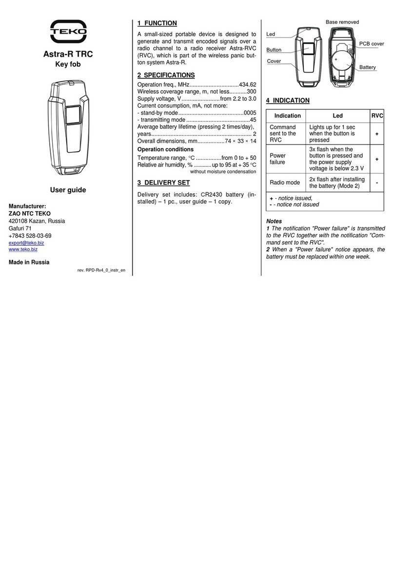
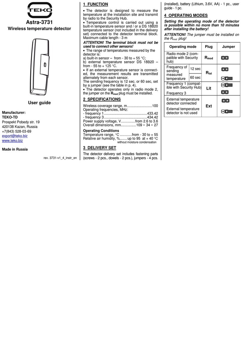
teko Astra-R TRC User manual

teko

teko Astra-R TRC User manual

teko Astra-551 User manual

teko

teko Astra-551 User manual

teko Astra-612 User manual

teko

teko Astra-612 User manual

teko Astra-515 ver.A User manual

teko

teko Astra-515 ver.A User manual

teko Astra-6131 User manual

teko

teko Astra-6131 User manual

teko Astra-43A User manual

teko

teko Astra-43A User manual

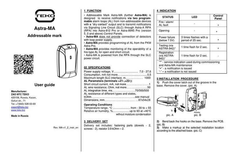
teko Astra-MA User manual

teko

teko Astra-MA User manual

teko Astra-551 User manual

teko

teko Astra-551 User manual

teko Astra-GB User manual

teko

teko Astra-GB User manual

teko Astra-3321 User manual

teko

teko Astra-3321 User manual

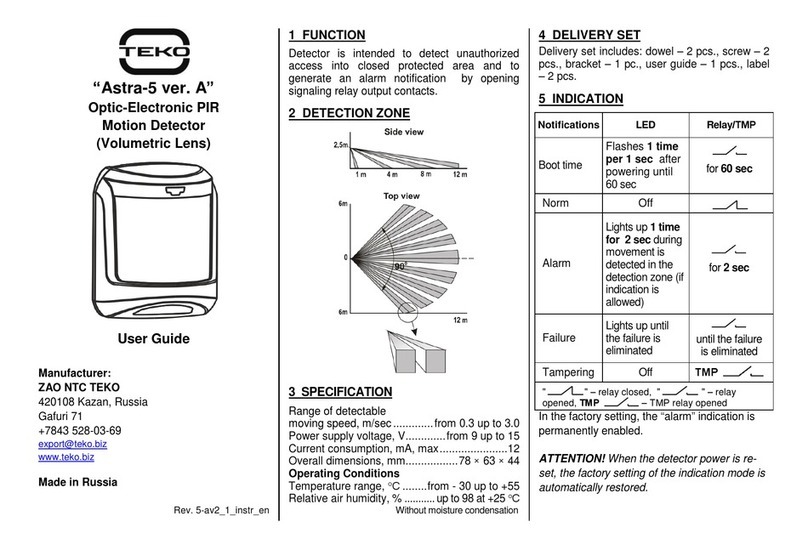
teko Astra-5 ver.A User manual

teko

teko Astra-5 ver.A User manual

teko Astra-A ILS User manual

teko

teko Astra-A ILS User manual

teko Astra-7 User manual

teko

teko Astra-7 User manual

teko User guide User manual

teko

teko User guide User manual

teko Astra-431 User manual

teko

teko Astra-431 User manual

teko Astra-531 DC Installation instructions

teko

teko Astra-531 DC Installation instructions

teko Astra-Z-3645 User manual

teko

teko Astra-Z-3645 User manual

teko Astra-642 User manual

teko

teko Astra-642 User manual

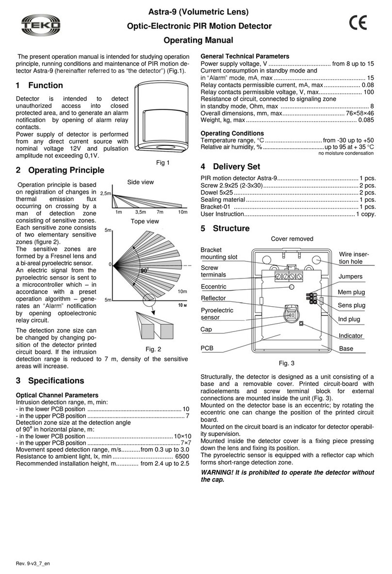
teko Astra-9 Installation instructions

teko

teko Astra-9 Installation instructions

teko Astra-621 User manual

teko

teko Astra-621 User manual

teko Astra-431 ver. RF User manual

teko

teko Astra-431 ver. RF User manual

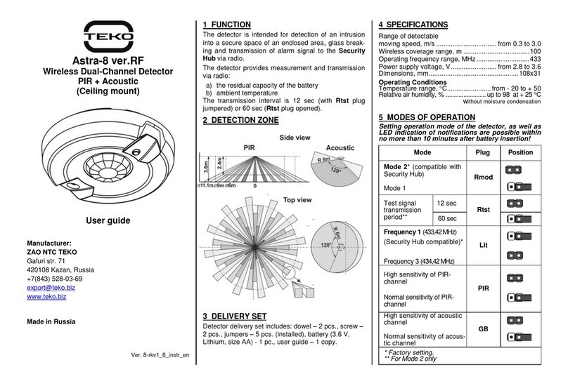
teko Astra-8 User manual

teko

teko Astra-8 User manual

teko Astra-5121 User manual

teko

teko Astra-5121 User manual

teko Astra-516 User manual

teko

teko Astra-516 User manual

Popular Security Sensor manuals by other brands

Honeywell Home PROSiXCOCN Installation and setup guide

Honeywell Home

Honeywell Home PROSiXCOCN Installation and setup guide

Duevi SIRPZ-RB-868 Operation

Duevi

Duevi SIRPZ-RB-868 Operation

RKI 65-2483RK Operator's manual

RKI

RKI 65-2483RK Operator's manual

Nortech PD160 Enhanced Series user manual

Nortech

Nortech PD160 Enhanced Series user manual

Omron K8AC-H2 manual

Omron

Omron K8AC-H2 manual

Agilent Technologies G8610 Series Quick reference card

Agilent Technologies

Agilent Technologies G8610 Series Quick reference card

Shinko SE2EA-1-0-0 instruction manual

Shinko

Shinko SE2EA-1-0-0 instruction manual

Det-Tronics X Series instructions

Det-Tronics

Det-Tronics X Series instructions

ACR Electronics COBHAM RCL-300A Product support manual

ACR Electronics

ACR Electronics COBHAM RCL-300A Product support manual

TOOLCRAFT 1712612 operating instructions

TOOLCRAFT

TOOLCRAFT 1712612 operating instructions

Elkron IM600 Installation, programming and functions manual

Elkron

Elkron IM600 Installation, programming and functions manual

Bosch WEU PDO 6 Original instructions

Bosch

Bosch WEU PDO 6 Original instructions

THORLABS PDA10JT user guide

THORLABS

THORLABS PDA10JT user guide

Waeco UV-DETECT operating manual

Waeco

Waeco UV-DETECT operating manual

Intermatic IOS-DSIMF manual

Intermatic

Intermatic IOS-DSIMF manual

Siemens AZL66 Series manual

Siemens

Siemens AZL66 Series manual

BTI Profiline Multi Finder operating instructions

BTI

BTI Profiline Multi Finder operating instructions

Challenger SL01 instruction manual

Challenger

Challenger SL01 instruction manual

manuals.online logo
manuals.online logoBrands
  • About & Mission
  • Contact us
  • Privacy Policy
  • Terms and Conditions

Copyright 2025 Manuals.Online. All Rights Reserved.

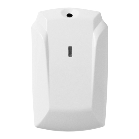
Astra-GB
Acoustic Surface Glass Break
Detector
User Instruction*
Sales:
Controlex GmbH
Philosophenweg 31-33
47051 Duisburg,Germany
+49 (0) 203/393 91 188
info@controlex.eu
www.controlex.eu
Warranty service and
technical support:
TEKO-TD
Prospect Pobedy str. 19
420138 Kazan, Russia
+7(843) 261-55-75
[email protected]z
www.teko.biz
Made in Russia
Rev. GB-v1_0_instr_EN
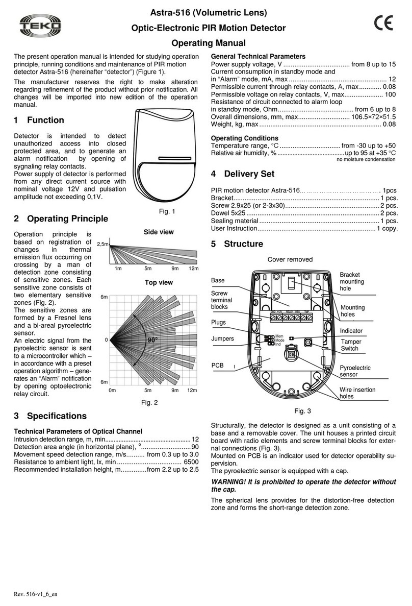
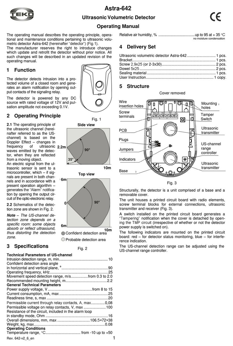
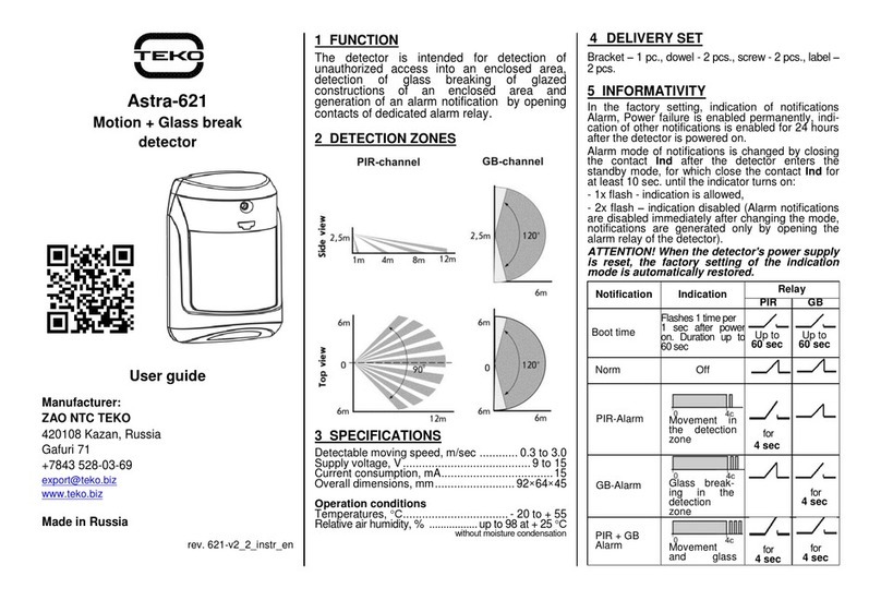
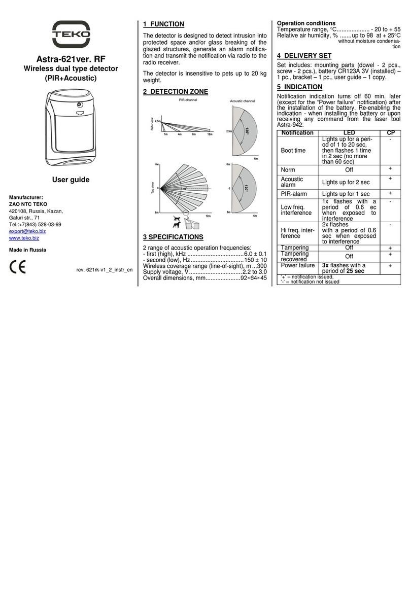
1 FUNCTION
The detector is designed to detect destruction
of glasses, glazed structures of enclosed area
and generate an alarm notification by opening
of signaling relay contacts.
2 DETECTION ZONE
3 SPECIFICATIONS
Maximal detection range, m........................... 6
Operating frequencies:
first, Hz ..............................................6000±100
second, Hz.............................................150±10
Power supply voltage, V.............from 8 up to 15
Current consumption, mA, max......................12
Overall dimensions, mm.....................87×54×27
Operating Conditions
Temperature range, °С........from - 20 up to +50
Relative air humidity, % ...........up to 95 at +35 °С
Withoutmoisture condensation
4 DELIVERY SET
Delivery set contains holders and fasteners
(dowel –2 pcs., screw –2 pcs.).
5 OPERATING MODE
Operating mode
Plug
name
Jumper
position
Interference
indication ON
Interference
indication OFF
Green
Alarm indication
ON
Alarm indication
OFF
Red
“Alarm memory”
ON
“Alarm memory”
OFF
Mem
Min sensitivity
Sens0
Sens1
Low sensitivity
High sensitivity
Max sensitivity
Confident detection area
Probable detection area
(for determination procedure see p.9)
6 INSTALLATION LOCATION
1) Recommended installation height is at least
2m and at a distance not more than 6m from
the most distant spot of protected glass.
2) The detector cannot be used in premises
with high level of acoustic interference.
3) Alarm loop wires should be located far from
power cables.
To eliminate false alarm hazards
1) It is recommended close doors and vents,
switch off fans, loud-speakers and other possi-
ble sources of acoustic interference in the room
during protection period.
2) The detector's location should provide di-
rect visibility of all secured glass parts; masking
the detector with decorative curtains is not al-
lowed, as sensitivity may be lost.
Not recommended installation locations
7 INSTALLATION PROCEDURE
1) Remove cover
2) Remove PCB
3) Push out blank of
wire insertion hole.
4) Install on the wall.
Detector base should be positioned strictly
as per figure!
4) Replace PCB and
perform wiring
(see par.8)
5) Perform AC-channel
testing (see par.9)
8WIRING
Perform wiring to detector`s terminals in
accordance with control panel operating manual.
RES –terminating resistor connection terminal;
TMP –detector tampering control terminals;
RELAY –terminals for detector connection to
alarm loop;
+12V, GND –power supply terminals.
9 AC-CHANNEL TEST
1) Install jumpers on Green, Red, Sens0,
Sens1 plugs. Remove jumper from Mem plug.
2) Close detector.
3) Power detector ON.
Apply non-destructive strike to the most distant
part of the protected glass.
3) At the detection moment the red LED should
light up for 7s and relay shouldopen (check
with control panel) or green LED should dou-
ble-flash one time.
10 WARRANTY
The operation warranty period is 5 years from the date
of operation start-up but no longer than 5 years 6
months from the date of manufacturing subject to the
requirements of Operating Manual.
*For more detailed information refer to detector
Operating Manual available for free from
www.controlex.eu.
Hooks