manuals.online logo
Brands
  1. Home
  2. •
  3. Brands
  4. •
  5. teko
  6. •
  7. Security Sensor
  8. •
  9. teko Astra-A ILS User manual

teko Astra-A ILS User manual

Astra - A ILS
Short Circuit Isolator
User guide
Manufacturer:
ZAO NTC TEKO
420108, Russia, Kazan,
Gafuri str., 71
Tel.:+7(843) 528-03-69
[email protected]
www.teko.biz
Made in Russia
Rev. ILS-v3_0_instr_en
1 FUNCTION
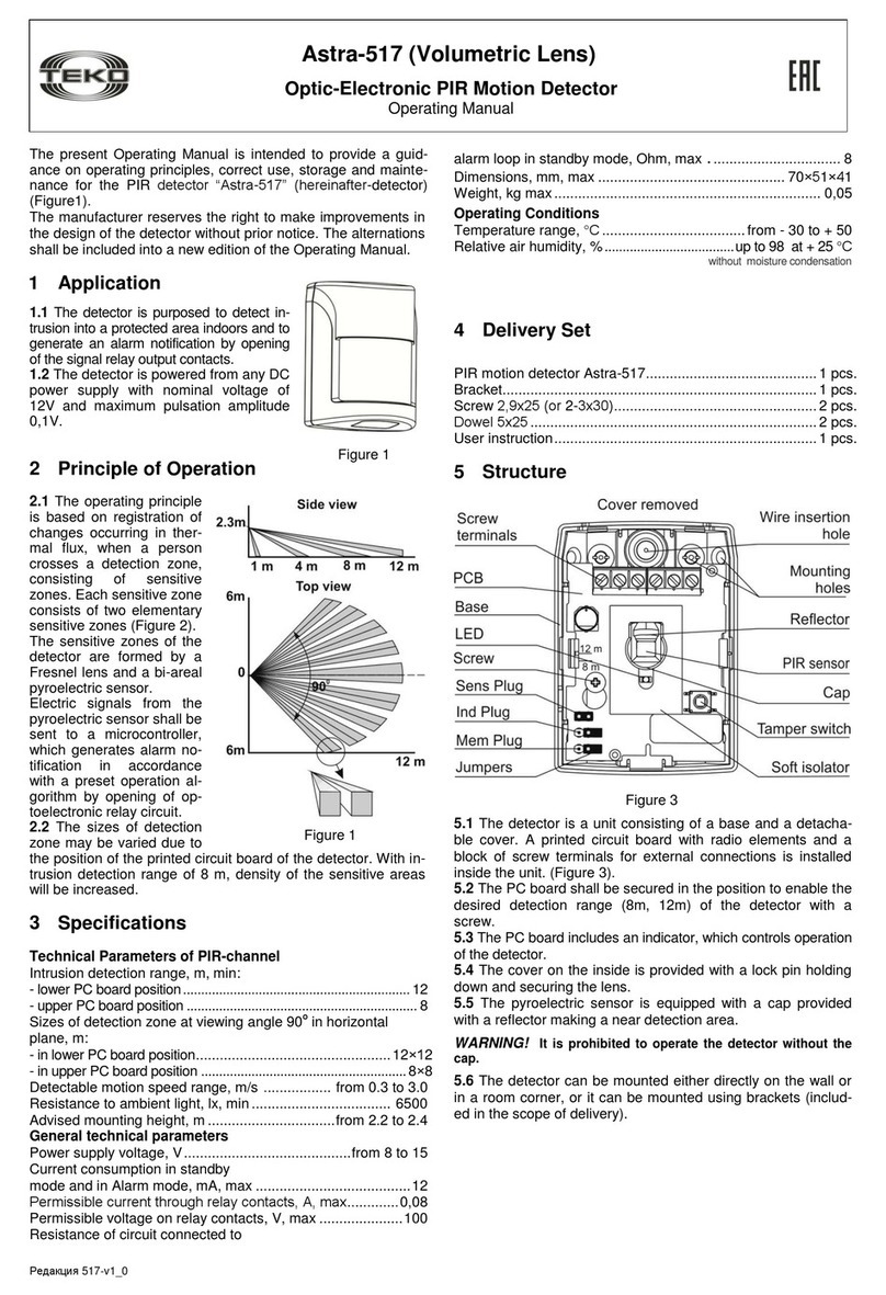
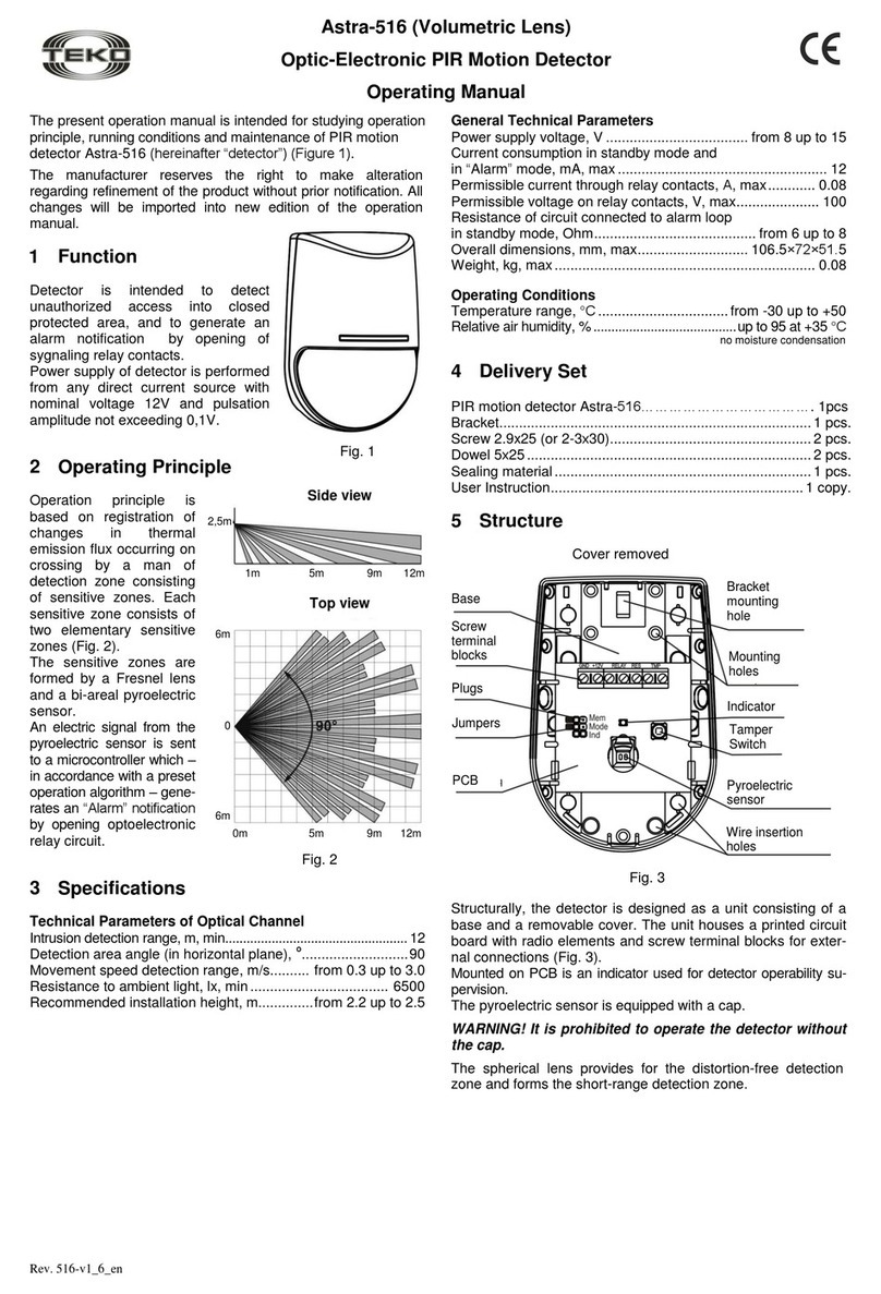
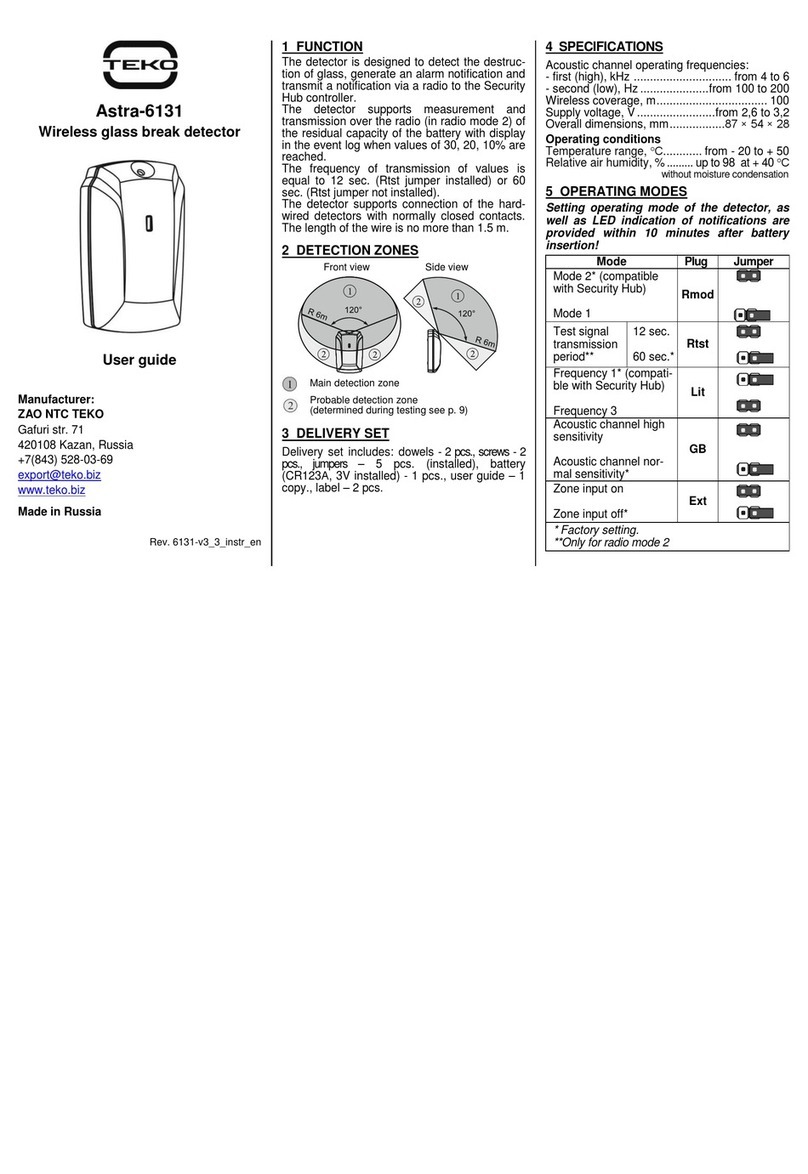
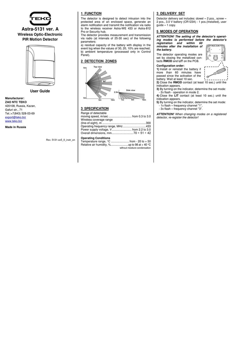
• Isolator (further “Isolator” or “device”) is an
unaddressed device designed for installation in
SLC or RS-485 interface line, formed by the
Control Panel Astra Pro.
• The Isolator is designed for automatic isola-
tion of an SLC segment or a section of the RS-
485 interface line (with extender), in which a
short circuit has occurred. The Isolator is de-
signed to protect and maintain the system
operability in case of a single failure of the SLC
line, to accelerate the search for the location of
the failure.
• The Isolator is powered by:
- in SLC - the Extender through the SLC power
circuit,
- in RS-485 interface - the nearest Extender
power supply circuit.
In case of power failure, the recovery of the
Isolator SLC power line occurs when the power
supply voltage is higher than 15 V.
2 SPECIFICATION
Power supply voltage, V.................... 7.5 –27.6
Current consumption, mA, no more than......... 4
Maximum cable cross-section for connecting to
terminals, mm...............................................2.5
Overall dimensions, mm.....................87×54×28
Operating Conditions
Temperature range, °С............from - 30 to + 55
Relative air humidity, %..........up to 93 at +40°С
without moisturecondensation
3 DELIVERY SET
Dowels –2 pcs., screws –2 pcs., sticker –2 pcs.
4 INDICATION
Table 1
Status
Reason
LED
Standby mode
Norm
ON
Power failure
L1 or L2 (SLC
only)
Short circuit of
the power
supply line
connected to
L1 or L2, or
voltage below
8 V
1 time flashes
with a period of
3 sec.
Failure of data
line L1 or L2
Short circuit of
the SLC data
line or RS-485
interface
connected to
L1 or L2
2 times flashes
with a period of
3 sec.
5 OPERATING MODES CHANGE
By directing a laser beam of Astra-942 laser
pointer to the Isolator indicator we can do the
following:
- disable/enable indication of Isolator in
StandBy mode (red LP button)
- disconnect/connect a part of SLC circuit
(power and data interface) (bottom LP button)
- disable/enable the line Isolator function
(middle LP button).
Note:
1.The Isolator operating modes switching is performed
at each laser beam directing to the Isolator indicator.
When the Isolator is illuminated again by pressing the
same button (not earlier than 5 sec. after the previous
exposure), the operating mode of the Isolator is invert-
ed.
2.The Isolator "memorizes" its state before the power
is turned off and after the power is restored, it restores
its functions in the modes established before the
power was turned off.

6 INSTALLATION PLACE
6.1 Number of isolators:
- Up to 32 devices in one SLC;
- Up to 64 devices in one circuit interface RS-
485
6.2 Each SLC segment formed (between adja-
cent Isolators or between an Isolator and
the Extender) should not exceed 32 ad-
dressable devices
6.3 The cable length in the SLC segment
should not exceed 200 m.
7 INSTALLATION PROCEDURE
1) Remove the cover from the base
2)Remove the PCB
3)Make a marking at the selected installation
location according to the attached base (pic. c.).
b. c.
4)Get the SLC cables or RS-485 interface
cables and power supply from the nearest
Extention through the cable entry holes (pic.c.)
5)Fix the base of the Isolator to the selected
place.
6) Return the PCB to its place
7) Connect the cables to the terminals in
accordance with Table 2 and the selected
connection diagram
Terminal
Terminal function
In SLC
In RS-485
L1
А, В
Connecting
the data line
of the incom-
ing (or out-
going) SLC
Connecting
the RS-485
interface line
+, –
Connecting
the power line
of the incom-
ing (or out-
going) SLC
Connecting
the 12 (24) V
power line
from the near-
est Extender
according to
the connection
diagram
L2
А, В
Connecting
the data line
of outgoing
(or incoming)
SLC
Connecting
the RS-485
interface line
+, –
Connecting
the power line
of the out-
going (or
incoming)
SLC
Connecting
the 12 (24) V
power line
from the near-
est Extender
according to
the wiring
diagram
8 WARRANTY
Warranty period of operation - 5 years from the
date of commissioning, but not more than 5
years 6 months from the date of manufacture,
and subject to the requirements of the current
user guide.

Other teko Security Sensor manuals

teko Astra-531 AC Installation instructions

teko

teko Astra-531 AC Installation instructions

teko Astra-621 User manual

teko

teko Astra-621 User manual

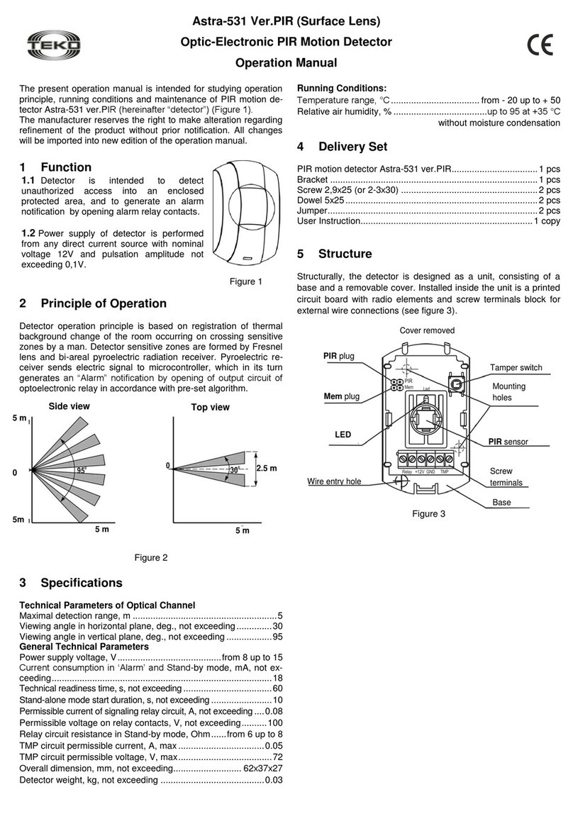
teko Astra-531 Ver.PIR User manual

teko

teko Astra-531 Ver.PIR User manual

teko Astra-642 User manual

teko

teko Astra-642 User manual

teko Astra-43A User manual

teko

teko Astra-43A User manual

teko Astra-516 User manual

teko

teko Astra-516 User manual

teko Astra-9 Installation instructions

teko

teko Astra-9 Installation instructions

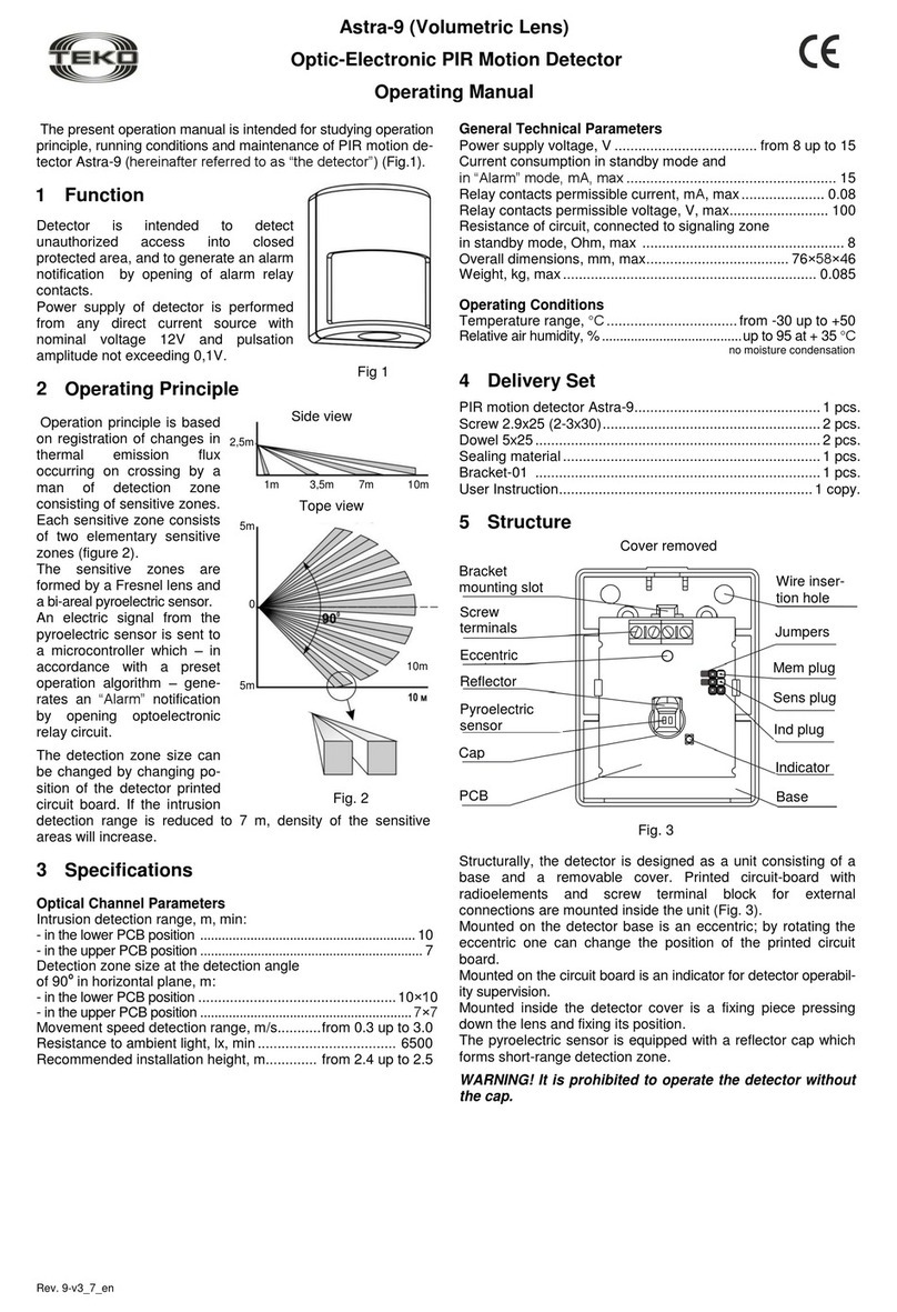
teko Astra-9 User manual

teko

teko Astra-9 User manual

teko Astra-551 User manual

teko

teko Astra-551 User manual

teko Astra-5131 User manual

teko

teko Astra-5131 User manual

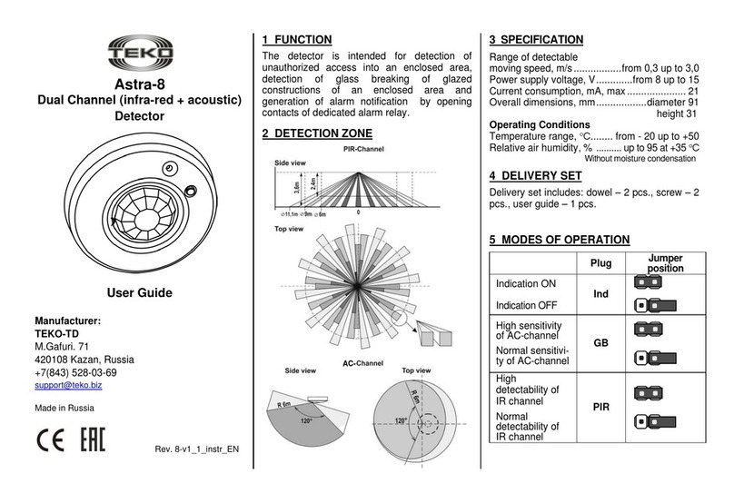
teko Astra-8 User manual

teko

teko Astra-8 User manual

teko Astra-6131 User manual

teko

teko Astra-6131 User manual

teko Astra-531 User manual

teko

teko Astra-531 User manual

teko Astra-531 PIR Installation instructions

teko

teko Astra-531 PIR Installation instructions

teko Astra-5121 User manual

teko

teko Astra-5121 User manual

teko Astra-621 RF User manual

teko

teko Astra-621 RF User manual

teko Astra-MA User manual

teko

teko Astra-MA User manual

teko Astra-551 User manual

teko

teko Astra-551 User manual

teko Astra-R TRC User manual

teko

teko Astra-R TRC User manual

teko Astra-621 User manual

teko

teko Astra-621 User manual

teko Astra-361 Installation instructions

teko

teko Astra-361 Installation instructions

teko Astra-3731 User manual

teko

teko Astra-3731 User manual

teko Astra-621 User manual

teko

teko Astra-621 User manual

teko Astra-GB Installation instructions

teko

teko Astra-GB Installation instructions

Popular Security Sensor manuals by other brands

Argus Security L-OP-SG Installation guides

Argus Security

Argus Security L-OP-SG Installation guides

Omron E8M - manual

Omron

Omron E8M - manual

SPX Radiodetection RD7000+ Operation manual

SPX

SPX Radiodetection RD7000+ Operation manual

Memco 618 Installation sheet

Memco

Memco 618 Installation sheet

Orno OR-CR-265 quick start guide

Orno

Orno OR-CR-265 quick start guide

Abra AK-325 quick start guide

Abra

Abra AK-325 quick start guide

Siemens FDOOTC241 Technical manual

Siemens

Siemens FDOOTC241 Technical manual

AVE AF45 62 Series quick start guide

AVE

AVE AF45 62 Series quick start guide

GJD D-TECT 1 manual

GJD

GJD D-TECT 1 manual

SWARCO MVAS Setup guide

SWARCO

SWARCO MVAS Setup guide

elobau eloProtect E 165ESK Series Translation of the original operating instructions

elobau

elobau eloProtect E 165ESK Series Translation of the original operating instructions

Siemens SLD4 Application notes

Siemens

Siemens SLD4 Application notes

Chauvin Arnoux C.A762 user manual

Chauvin Arnoux

Chauvin Arnoux C.A762 user manual

LUDLUM 70 System manual

LUDLUM

LUDLUM 70 System manual

BST Flamonitec IFR 400 operating manual

BST

BST Flamonitec IFR 400 operating manual

hager TX510 Setup instructions

hager

hager TX510 Setup instructions

Holmatro RA 531 Series manual

Holmatro

Holmatro RA 531 Series manual

Optex FMX-DT-X5 installation instructions

Optex

Optex FMX-DT-X5 installation instructions

manuals.online logo
manuals.online logoBrands
  • About & Mission
  • Contact us
  • Privacy Policy
  • Terms and Conditions

Copyright 2025 Manuals.Online. All Rights Reserved.