Xtool PS80 User manual

PS80
Diagnosis System
User Manual

PS80 Diagnosis System
Declaration
1. This manual is designed for the usage of PS80, applying to PS80 automotive
diagnosis platform.
No part of this manual can be reproduced, stored in a retrieval system or
transmitted, in any form or by any means (electronic, mechanical, photocopying,
recording, or otherwise), without the prior written permission of Xtool.
2. Use the device only as described in this manual. The user will be responsible
solely for the after-effects of violating the laws and regulations caused by using the
product or its data information; in this case Xtool will not bear any legal
responsibility.
3. Xtool shall not be liable for any incidental or consequential damages or for any
economic consequential damages arising from the accidents of individual users and
the third parties, misuse or abuse of the device, unauthorized change or repair of
the device, or the failure made by the user not to use the product according to the
manual.
4. All information, specifications and illustrations in this manual are based on the
latest configurations and functions available at the time of printing. Xtool reserves
the right to make changes at any time without notice.
5. is the registered trademark of SHENZHEN XTOOLTECH CO.,LTD.
6. In countries that the trademarks, service marks, domain names, logos and the
name of the company are not registered, Xtool claims that it still reserves the
ownership of the unregistered trademarks, service marks, domain names, logos and
the company name. All other marks for the other products and the company’s name
mentioned in the manual still belong to the original registered company.
You may not use the trademarks, service marks, domain names, logos and company
name of Xtool or other companies mentioned without written permission from the
trademark holder.
7. Please visit www.xtooltech.com for more information on the PS80.
8. Xtool reserves the right for the final interpretation of this manual content.
Xtool PS80 User Manual Instructions
Please read this user manual carefully before using the scanner.
When reading the manual, please pay special attention to the words “Note”,
“Caution” or “Warning”, read them carefully for appropriate operation.

PS80 Diagnosis System
Xtool PS80 Diagnosis System Main Unit Maintenance
Avoid shaking or dismantling the unit as it may damage the internal components.
Do not use hard or sharp objects to touch the LCD screen; do not use excessive force;
do not expose the screen to strong sunlight for a long period.
Caution: keep it away from water, moisture, high temperature or very low
temperature.
If necessary, calibrate the screen before testing to ensure the accuracy of LCD
performance.
Keep the main unit away from strong magnetic fields.
Operation Instructions
For safe operation please follow the instructions below:
Keep the scanner away from heat or fumes when using it.
If the vehicle battery contains acid, please keep your hands and skin or fire sources
away from the battery during testing.
Exhaust gas of vehicle contains harmful chemicals, please ensure adequate
ventilation.
Do not touch the cooling system components or exhaust manifolds when engine is
running due to the high temperatures reached.
Make sure the car is securely parked, Neutral is selected or the selector is at P or N
position to prevent the vehicle from moving when engine starts.
Make sure the (DLC) diagnostic link connector is functioning properly before starting
the test to avoid damage to the Diagnostic Computer.
Do not switch off the power or unplug the connectors during testing, otherwise you
may damage the ECU and/or the Diagnostic Computer.

PS80 Diagnosis System
Contents
CHAPTER ⅠAbout PS80 ...............................................................................................1
1. Appearance ................................................................................................................1
1.1. Front View...............................................................................................................1
1.2. Back View................................................................................................................1
2. Layout of PS80 Tablet.................................................................................................2
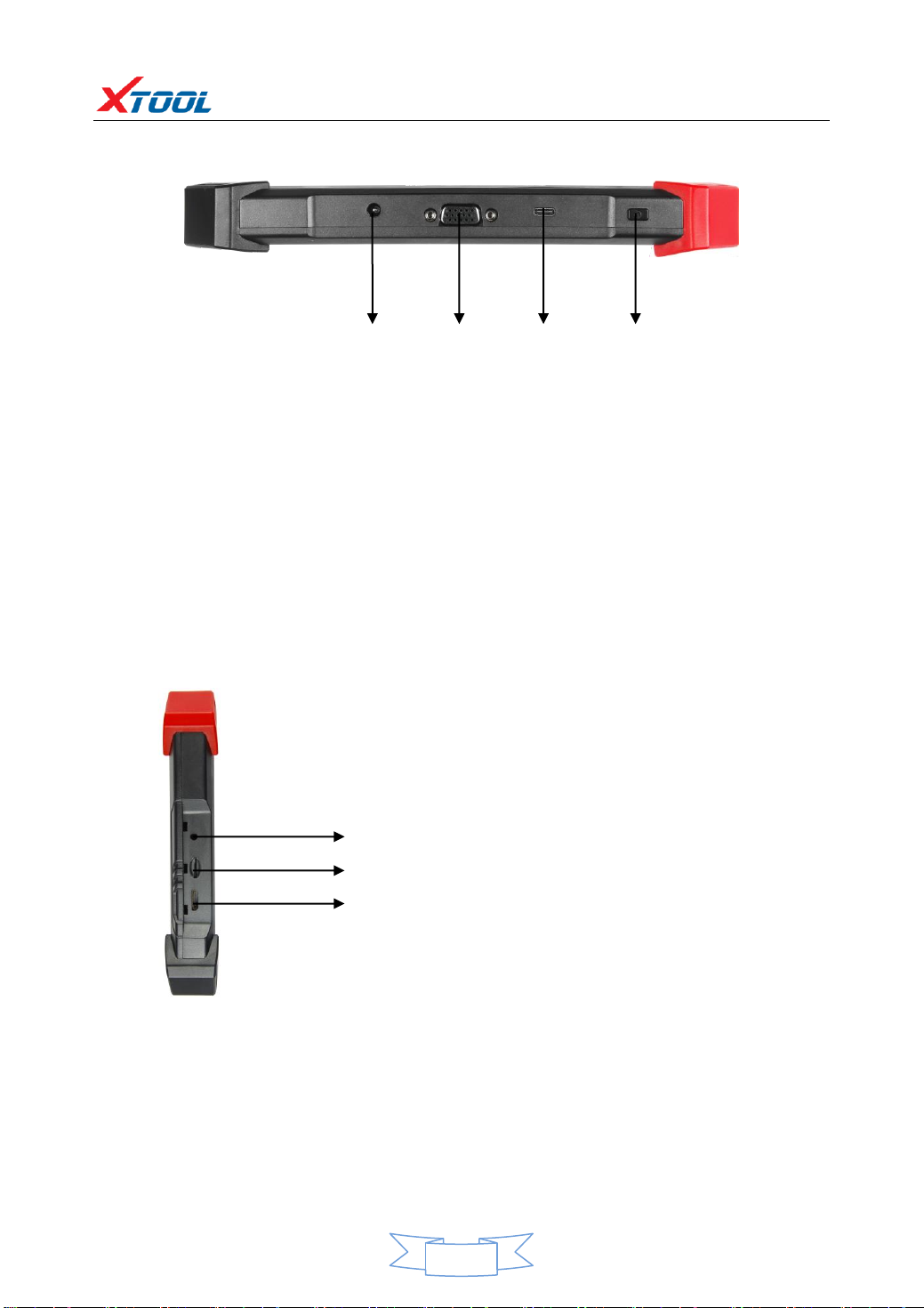
2.1. Top View of PS80 Tablet..........................................................................................2
2.2. Side View of PS80 Tablet.........................................................................................2
3. PS80 Technical Parameters.........................................................................................2
CHAPTER ⅡHow to Use PS80 ....................................................................................3
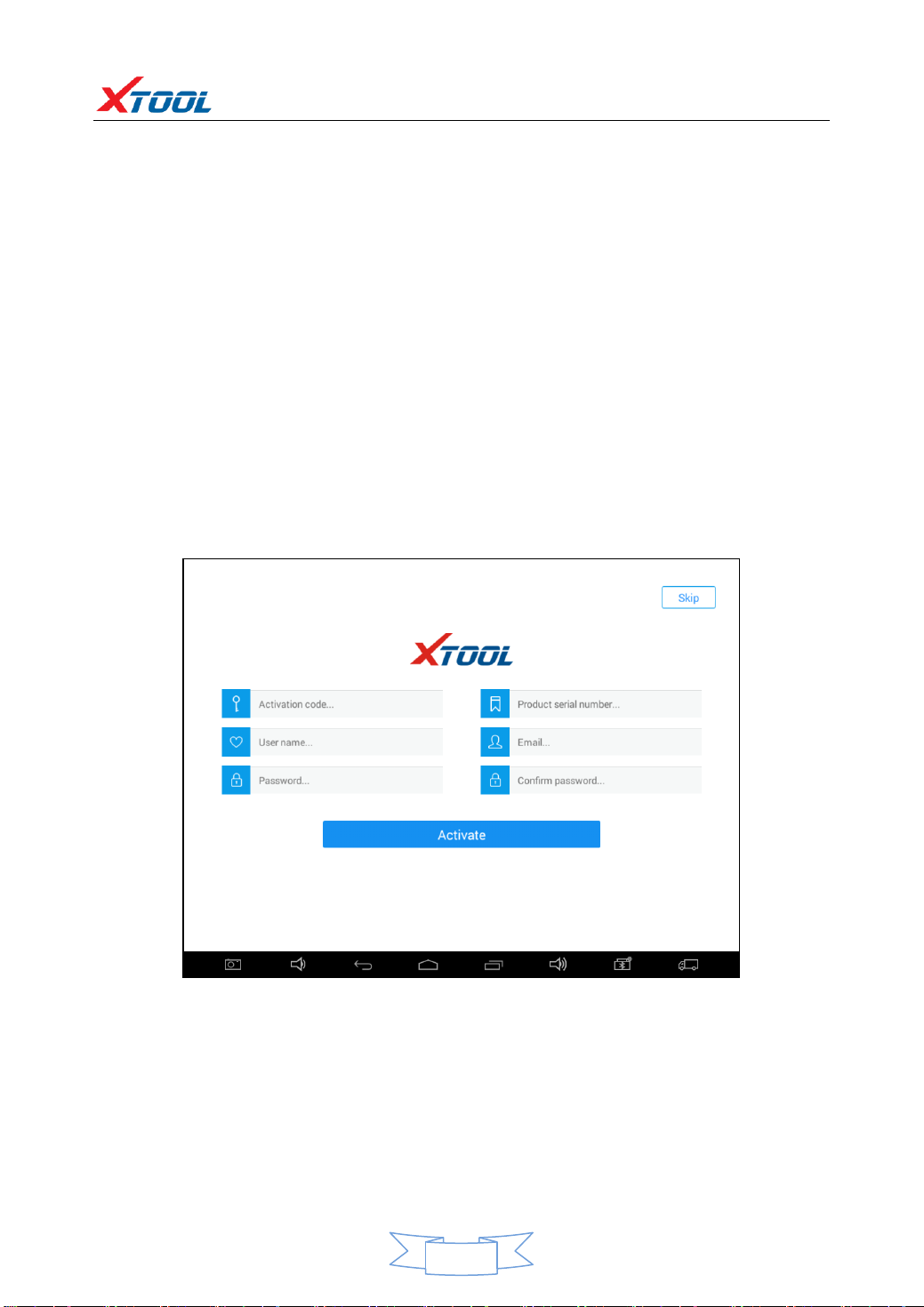
1. PS80 Activation ..........................................................................................................3
2. PS80 Main Interface and Functional Buttons Descriptions .......................................4
2.1. Main Interface.........................................................................................................4
2.2. Sub-menu and Functional Buttons .......................................................................5
2.3. Toolbar Functional Buttons.....................................................................................5
3. Vehicle Connection Diagnosis ....................................................................................6
3.1. Vehicle Connection Test..........................................................................................6
3.2. Precautions Before Use...........................................................................................6
4. Diagnosis ....................................................................................................................7
4.1. Menu Options .........................................................................................................7
4.2. Test Functions .........................................................................................................8
4.3. Read ECU .............................................................................................................10
4.4. Read DTCs..............................................................................................................10
4.5. Clear DTCs .............................................................................................................11
4.6. Read Live Data.......................................................................................................12
4.7. Special Functions ..................................................................................................15
4.8. Actuating Components Test ..................................................................................15
5. Settings.....................................................................................................................16
6. XCloud ......................................................................................................................17
7. Update......................................................................................................................17
8. Report.......................................................................................................................18
9. Remote.....................................................................................................................20
CHAPTER ⅢLocation of Diagnostic Link Connectors on Different Vehicle Models .21
1. Diagnostic Link Connectors Locations of Various Vehicle Models...........................21
2. Location Diagram of Vehicle Diagnostic Link Connectors........................................25
3. Diagnostic Link Connectors Terminal Definition and Communication Protocols ....25

PS80 Diagnosis System
1
CHAPTER ⅠAbout PS80
1. Appearance
1.1. Front View
1.2. Back View

PS80 Diagnosis System
2
2. Layout of PS80 Tablet
2.1. Top View of PS80 Tablet
①Charging port: Battery charging
②DB15 Port: Supports wired connection with car by the cable
③USB Type C Port: Compatible with HDMI TV port, and support for quick charging
④Power Button: Power on or power off
2.2. Side View of PS80 Tablet
3. PS80 Technical Parameters
Operating System:
Processor:
Memory:
Display:
Android
Quad-core 1.6GHz Processor
2G RAM,32G FLASH
8.0 inch capacitive touch screen with 1024x600p
resolution
①
②
③
④
①Earphone jacket
②USB2.0 Port: data synchronization with PC.
③Mini HDMI Port

PS80 Diagnosis System
3
Camera: Rear camera, 5.0 Megapixel, AF with Flashlight
Sensors:
Auto Input/Output:
Auto Input/Output:
Power and Battery:
Power Consumption:
Operating Temperature:
Humidity:
Dimension (L×W×H):
Gravity Sensor, Ambient Light Sensor
Microphone, Dual Speakers, 4-Band 3.5 mm
stereo/standard headset jack
4000mAh, 7.4V lithium-polymer battery
12V
29.6W
-20 to 50℃(-4 to 126℉)
<90%
240×177×30mm
CHAPTER ⅡHow to Use the PS80
1. PS80 Activation
1.1. Please activate PS80 before you use it to test vehicles. And please connect WiFi
first.
1.2. Input activation code (on the Quality Certificate cover), product serial number
(each device will have a serial number and activation code), nickname (workshop’s
name or user’s nickname), login account (can be your email address or cell phone
number) and password, the system will then save it. Activation is a one time process.
The diagnostic application will start after activation.

PS80 Diagnosis System
4
2. PS80 Main Interface and Functional Buttons Descriptions
2.1. Main Interface
Tap on PS80 application icon, the main interface and sub-menus will be shown as
below.▼

PS80 Diagnosis System
5
2.2. Sub-menus and Function Buttons
Function Buttons
Descriptions
Opens the PS80 diagnostic application. It can read diagnostic
information, view live data, perform actuation tests and special
functions etc.
By selecting “Setting”, users can access the language setting
and other system related settings.
Online Communication Platform for PS80 users.
(English version is coming soon)
Click UPDATE after PS80 is connected to internet, then you can
download the latest diagnostic software directly to PS80.
Users can view all the diagnostic reports and diagnostic data
generated in the diagnosis process.
Users can get remote help and support when needed.
2.3. Toolbar Function Buttons
Function Buttons
Descriptions
For screen captures or for turning on the camera
Turn down the volume
Returns to previous interface
Returns to the main interface of Android System
Shows (recently used) applications
Turn up the volume
Click here to return to the diagnostic interface
Click here to return to diagnostic vehicle models interface

PS80 Diagnosis System
6
3. Vehicle Connection Diagnosis
3.1. Vehicle Connection Test
a. Turn on PS80 tablet
b. Connect cables and PS80 in following order: ①→②→③→④
c. Switch on the ignition and tap on PS80 application to test vehicles. (Shown as follows)
①PS80 Mainframe
②Main Test Cable
③OBDII Connector
④Vehicle
3.2. Precautions before Use
3.2.1. The vehicle power supply has to meet the normal voltage limits DC 9-12V.
3.2.2. Users should check the position of the DLC port and ensure the OBDII 16pin
connector and the DLC port are correctly aligned before attempting to connect.
3.2.3. When taking some special functions tests, users are required to operate the
device according to operating instructions. For vehicle, it has to strictly meet the
requirements, for example, the conditions that some vehicle models need to be
reached are as follows: engine temperature 80℃/105℃, turn off the loads (such
as headlights, air-conditioner, etc.), put accelerator pedal in released position, etc.
3.2.4. If users can not find the tested vehicle model or electronic control system in
the PS80 test menu, they may need to update the software or consult Xtool
technical service department.
3.2.5. Please ensure that only official XTOOL cables and connectors are used to
prevent damage to the unit.
3.2.6. Before powering off the unit, please ensure that you cancel or complete the

PS80 Diagnosis System
7
current task or function and return to the main interface, then power off.
3.2.7. Do not use excessive force to operate the touch screen.
3.2.8. During long period of non-use, please disconnect the power and turn off the
PS80 unit.
4.Diagnosis
4.1. Menu Options
4.1.1. After the scanner is connected to the vehicle and paired with PS80 mainframe
via wired or wireless connection, diagnosis can be performed. The diagnostic
interface is as shown below:
4.1.2. Users can choose the relevant menu for the vehicle being tested: selection for
Europe will enter the European cars menu, selection for Asia will enter the Asian
cars menu, selection for America will enter the American cars menu. Users also can
input the vehicle model to search.
4.1.3. Besides the usual system diagnostic functions, XTOOL have also developed a
series of special diagnostic functions for certain vehicles as follows:

PS80 Diagnosis System
8
4.2. Test Functions
4.2.1. Using VW as an example, select Diagnosis, then select EUROPE.Choose the
VW word. If the word is not showing on the screen, please swipe up or down to
display it.
PLEASE NOTE: Different vehicles have different menus and systems.
Common main function menu includes the following options:
Read ECU: This function is to read the ECU version information, which is the
equivalent of “System Identification” or “System Information” in some electronic
control systems.

PS80 Diagnosis System
9
This will allow you to read ECU related software and hardware versions, models and
production date of diesel engine, part number, etc.
Read DTCs: read the trouble codes that are stored in the ECU.
Clear DTCs: clear current and historical trouble codes memory in ECU. The trouble
codes can not be erased without eliminating the fault that the code relates to. TIP:
Save or print the currently stored fault codes before clearing them to provide help in
the case of an intermittent fault.
Read Live Data: This will allow you to read the parameters of the system being
interrogated, such as oil pressure, temperature, engine speed, fuel oil temperature,
coolant temperature, intake air temperature, etc.
Special Functions: Typically these will include Injector programming, DPF
Regeneration/reset, component learning etc.
Actuation/Activate Components Test: Activations allow you to operate supported
components for troubleshooting purposes. Components range from instrument
cluster indicators, to the engine injection valves, to the boot lid latch.
Activations are also used to test components for function and to check systems for
correct operating ranges.
4.2.2. Toolbar function buttons descriptions
Function Buttons
Descriptions
Returns to previous interface
Print test data
Click to record the data, click again to send your
feedback to XTOOL service center
After clicking the data record button the second time the data feedback page will
appear as shown below, showing diagnostic software version, vehicle being tested,
and the steps performed in the diagnostic process. Users can then enter the nature
of the problem and any other relevant information and send the form to the Xtool
engineering department.

PS80 Diagnosis System
10
4.3. Read ECU
This function is used to read ECU version information, which is the equivalent of
“System Identification” or “System Information” in some electronic control systems.
This will allow you to read ECU related software and hardware versions, models and
production date of diesel engine, part number, etc. shown below:
4.4. Read DTCs
Select Read Fault Codes to read the trouble codes stored in the ECU. The screen will
show the trouble codes and their definition, shown below:

PS80 Diagnosis System
11
Tip: In the process of diagnosis, if the device shows “System is OK” or “No Trouble
Code”, it indicates that the ECU has not detected a fault in any of the circuits that it
monitors. If there is a fault which is not being recorded it may be that the fault is
with a part of the system not under the control of ECU, such as a mechanical system
fault. It is also possible that the signal of a system sensor may be incorrect but still
within the ECUs stored limits, this can be verified in Live Data.
4.5. Clear DTCs
4.5.1. Return to the previous step, select Clear Fault Codes to clear the current and
historical trouble codes memory in ECU. Performing this function will clear all the
current and historical trouble codes. Please ensure that the trouble codes have been
recorded before clearing, shown below:

PS80 Diagnosis System
12
4.5.2. Click YES to confirm the operation, if the communication is normal, it will
show “Trouble Codes Successfully Cleared” or “Trouble Codes Cleared”. Generally,
users will need to re-read trouble codes after clearing them to confirm that the
trouble codes have been cleared.
4.6. Read Live Data
System control units or ECUs send out operating parameters and working status of
various components in the form of an Electronic Signal, here Electronic Signal refers
to Live Data. Common Engine Live Data includes Engine Speed, Throttle Position
Sensor Voltage, Oxygen Sensor Voltage, Coolant Temperature, Spark Advance Angle,
Idle Speed Switch State, Intake Air Temperature, Intake Pressure, etc.

PS80 Diagnosis System
13
Tip: Live Data is important function that can be used to help technicians further
diagnose a problem. This function requires technicians to be familiar with sensor
data of each system, control signals and control modes. Tip: Save known good live
data readings for comparison.
(The following are some test conditions and typical values of common live data)
Test Items
Unit
Normal
Data
Test Conditions & Typical Values
1.Engine Speed
rpm
0-6000
Engine warmed-up: 750-850rpm
2.Engine Coolant
Temperature
℃
-40-150
Engine warmed-up: 85-95℃
3.Throttle Percentage
0-100
Throttle closed: 0%,
Throttle wide-open: >85
4.Injecting Pulse Width
ms
0-15
Engine warmed-up: 3.5-4.5ms
5.Intake Air
Temperature
℃
-40-150
Show value a little higher than
ambient temperature
6.Battery Voltage
v
0-15
Idle speed: 11-13.5V
7.Injection closed-loop
correction
0-1.99
8.Load
ms
0-15
Dependent on throttle position etc
9. Angle of Ignition
Advance
℃
0-50
Engine warmed-up: 5-15 ℃
variations
10.Air Intake
kg/h
0-255
Engine not started: 0
11.Intake Pressure
hpa
0-1013
Engine not started: 1013hpa
12. Idle-speed
Adjustment Status
0-255
13.Oxygen Sensor
mv
0-1000
Engine warmed-up: 50-960mv
variations
Display Modes
There are three modes with which to view Live Data, users can choose the optimum
mode according to their own needs and different parameter types.
Digital Mode: Displays parameters in numerical form.
Dashboard Mode: Displays parameters in the form of simulated instrument graphics.
Graph Mode: Displays parameters in graph form.

PS80 Diagnosis System
14

PS80 Diagnosis System
15
4.7. Special Functions
Different vehicle makes and models will have different special functions.
4.8. Actuation/Active Components Test
Test Conditions: Ignition on engine off.
If the engine is started or an engine rotation speed signal is received, component
actuation will be interrupted.
In the process of actuating components, a single component will always be in the
trigger status until the next component is activated.

PS80 Diagnosis System
16
Actuating components can be checked by hearing or touching.
4.8.1. Return to Dynamic Diagnostic Data, enter Test Actuator and it will show the
menu of the components that are available to actuate, shown below:
Tip: Actuating Components Test performs function tests for system components. When
performing this function, the diagnostic tool will simulate the ECU signal to enable the
user to judge whether the actuating components or circuits are working correctly.
5. Settings
By selecting Settings users can set the language, unit and other system related
options:
Languages: select the language. Please tick the required option from the
multi-language options on the right.
Table of contents
Other Xtool Diagnostic Equipment manuals