BEGA Gantenbrink-Leuchten KG · Postfach 31 60 · 58689 Menden · info@bega.com · www.bega.com 3/7
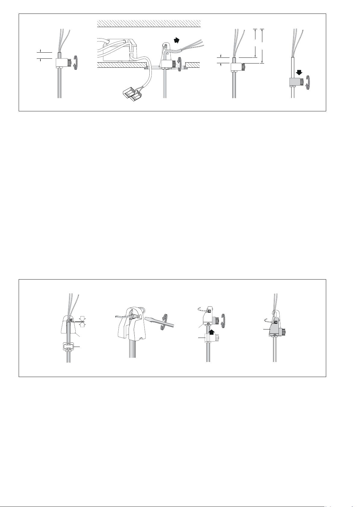
Vor der Montage zu beachten:
Vor dem Anbringen des Zugentlasters an
der Leuchtenleitung, muss sichergestellt
sein, dass die Leuchtenleitung zuerst
durch die unterseitige Lochbohrung der
Baldachinabdeckung geführt wird.
Zum Anschluss und zur Ansteuerung weiterer
Leuchten ist die Verwendung einer bauseitigen
Abzweigdose aus Kunststoff in entsprechender
Schutzklasse erforderlich.
Prior to installation, please note:
Make sure that the luminaire cable is
routed through the hole drilled into the
underside of the canopy cover before
attaching the strain relief to the luminaire
cable.
For connection and control of further
luminaires, the use of an on-site synthetic
junction box of the appropriate protection class
is required.
À noter avant l’installation:
avant de raccorder la décharge de traction
au câble du luminaire, il faut d’abord faire
passer le câble du luminaire à travers la
perforation de la paroi inférieure du capot
du cache-piton.
Pour le raccordement et la gestion d'autres
luminaires, l'utilisation d'une boîte de dérivation
en plastique (à prévois sur le chantier) de la
classe de protection appropriée est requise.
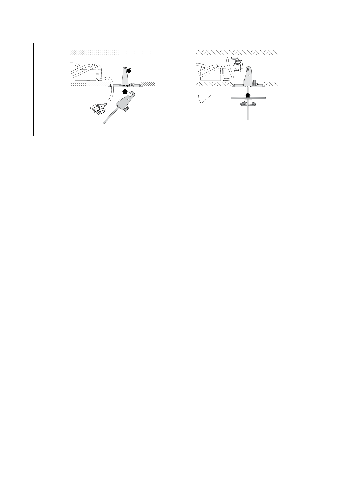
Für die Befestigung der Leuchte ist auf
ausreichende Tragfähigkeit der Deckenäche
zu achten.
Bitte prüfen Sie nach der Montage die
sichere Befestigung der Leuchte.
When mounting the luminaires, it must be
ensured that the ceiling surface has sufcient
load-bearing capacity.
Please check the secure mounting of the
luminaires after installation.
Il convient de vérier que la capacité de charge
du plafond est sufsante pour la xation du
luminaire.
Une fois l’installation terminée, veuillez
vérier que le luminaire est solidement
xé.
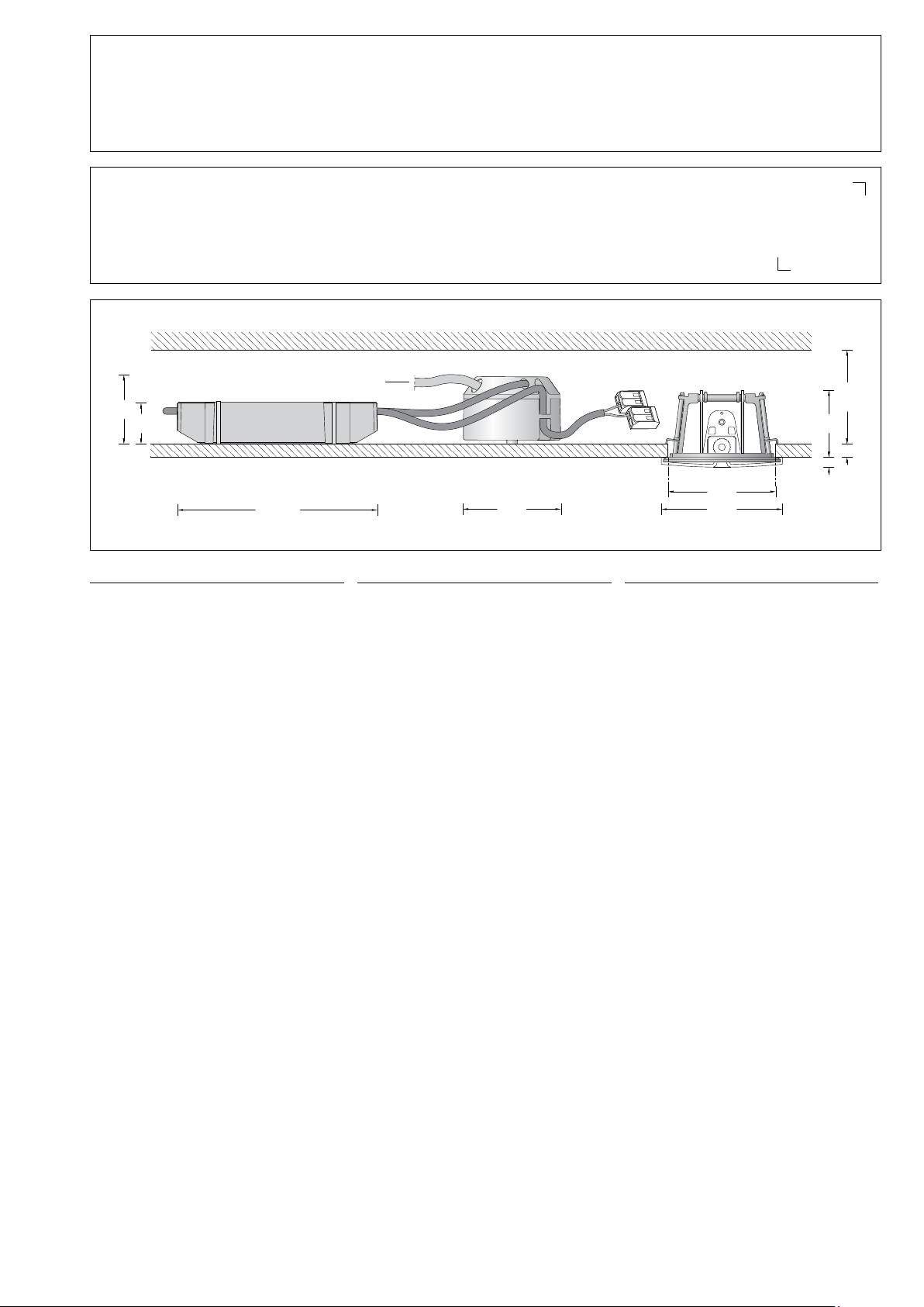
Montage
Netzanschlussleitung ca. 80 mm abisolieren.
Deckel von Anschlussdose des Smart DALI-
Controllers lösen.
Netzanschlussleitung (bis Ø11mm,
max.5×1.5@) durch die Lochbohrung
im Deckel der Anschlussdose führen und
Leitungsmantel mit dem beiliegenden
Kabelbinder unter Zuhilfenahme der
Fixierlaschen im Deckel befestigen.
(Kabelbinder und Data Matrix Code-Etiketten
zusammen in separatem Beutel).
Installation
Strip approx. 80 mm of insulation from the
power connecting cable.
Remove the cover of the connection box from
the Smart DALI-Controller.
Guide the mains supply cable (up to Ø 11 mm,
max. 5 ×1.5@) through the borehole in the
cover of the connection box and secure the
cable sheath with the enclosed cable tie using
the xing straps in the cover.
(Cable tie and Data Matrix Code labels together
in separate bag).
Installation
Dénuder le câble de raccordement de
±80mm.
Détacher le couvercle de la boîte de
raccordement du Smart DALI Controller.
Introduire le câble de raccordement (jusqu'
à Ø 11 mm, max. 5 ×1.5@) par le trou du
couvercle de la boîte de raccordement et xer
la gaine du câble avec l’attache de câble à à
l'aide des pattes de xation dans le couvercle.
(Attaches de câble et étiquettes de code
DataMatrix ensemble dans le sachet séparé).
Bitte beachten Sie:
Der Smart DALI-Controller kann nur allein
in einer DALI-Linie verbaut werden und darf
nicht mit einer anderen DALI-Steuerung
zusammenhängend betrieben werden.
Der Smart DALI-Controller erstellt
sekundärseitig eine eigene DALI-Linie, an
der ausschließlich bis zu 14weitere DALI-
Betriebsgeräte angeschlossen werden können.
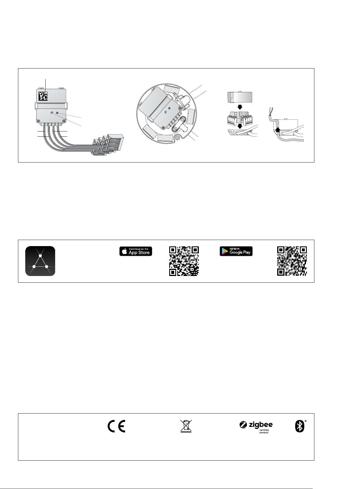
Die Ansteuerung des Smart DALI-Controller
erfolgt über die App BEGA Smart.
Please note:
The Smart DALI Controller can only be used in
a DALI line alone, and cannot be operated in
conjunction with another DALI control system.
The Smart DALI Controller creates a separate
DALI line on the secondary side, to which only
up to 14 additional DALI operating devices can
be connected.
The Smart DALI Controller is then controlled via
the BEGA Smart app.
Attention:
Le Contrôleur Smart DALI peut seulement être
monté seul sur une ligne DALI; il ne doit pas
être utilisé avec un autre pilotage DALI.
Le contrôleur Smart DALI crée une ligne DALI
séparée sur le côté secondaire, laquelle admet
exclusivement la connexion de 14appareillages
DALI supplémentaires au maximum.
Le pilotage du contrôleur Smart DALI s’effectue
via l’application BEGA Smart.
DA
N
PE
L
DA
max . 14
DALI Betriebsgeräte
DALI operating devices
Appareillages DALI
L
N
DA
DA
L
N
DA
DA
PE
DALI Betriebsgerät
DALI operating device
Appareillage DALI
-
+
Bauseitige Abzweigdose
On-site junction box
Boîte de dérivation (à prévoir sur le chantier)
DA
DA
PE
N
L
Smart DALI
Controller
WICHTIG: Nur die separat beiliegenden
Data Matrix Code-Etiketten sind identisch mit
dem Aufdruck des integrierten Smart DALI-
Controllers dieser Installationskomponente.
Ein Vertauschen dieser Data Matrix
Code-Etiketten mit Etiketten weiterer
eingesetzter Smart DALI Controller
kann zu falscher Zuordnung bei der
Konguration führen!
Bewahren Sie diese Etiketten mit zuordnenden
Angaben zu Installationsort (Raumbezeichnung,
Lage etc.) in Ihrer Dokumentation auf.
IMPORTANT: Only the separately enclosed
data matrix code labels are identical to the print
on the integrated Smart DALI-Controller of the
installation component.
Mismatching these data matrix code
labels with the labels of other Smart DALI
Controllers may cause faulty assignment
during conguration!
Please save these labels with the assigned
specications for the location site (room
description, location, etc.) with your
documentation.
IMPORTANT: Seules les étiquettes de
code DataMatrix jointes sont identiques
à l’inscription gurant sur le Smart DALI-
Controller intégré de ces composants
d’installation.
Le remplacement de ces étiquettes de
code Data Matrix avec des étiquettes
d’autres Smart DALI Controller utilisés
peut conduire à une conguration
erronée!
Conservez ces étiquettes avec les informations
liées au site de l’installation (désignation de la
pièce, situation etc.) dans vos documents.