CDVI C2R User manual

G0301FR0145V01 Ed : 02/2004 Français
1
CARACTERISTIQUES TECHNIQUES
. Alimentation 12V DC -8% à +20%
. Alimentation 12V alternatif +15%
. Consommation au repos < 5 mA
. Consommation maximale < 100 mA
. Protection IP 43/5
. Température Fonctionnement : -20° C à +70° C
. Sortie relais : 2 relais 1RT 24V - 2A
. 1 contact boucle surveillance à l’arrachement ou à l’ouverture
. 1 voyant jaune indiquant : Frappe au clavier
Entrée en programmation
Défaut programmation
. 1 voyant vert indiquant la commande du relais 1
. 1 voyant rouge indiquant la commande du relais 2
. 2 picots à strapper pour retour aux codes par défaut
(à la mise sous tension)
. Codes maître et utilisateurs à 5 termes
. Sauvegarde des codes et modes de commande des relais
en cas de coupure alimentation
. Temporisations de sécurité clavier
. Entrée Bouton poussoir pour commande relais 1
PROGRAMMATION USINE
En sortie d’usine, les codes en mémoires sont les suivants :
CODE 1 : 11111 sortie relais 1 mode impulsionnel 1 seconde
CODE 5 : 22222 sortie relais 2 mode impulsionnel 1 seconde
CODE 0 : 00000 code maître d’entrée en programmation
PROGRAMMATION DU CODE MAITRE
Taper deux fois de suite 00000
Le voyant jaune s’allume fixe.
Taper 0 puis les 5 termes de votre choix, le voyant jaune s’éteint 1 seconde.
Taper sur pour sortir de la programmation, le voyant jaune s’éteint.
* A chaque appui le voyant s’éteint 0.1s indiquant la prise en compte de la touche.
PROGRAMMATION DES CODES UTILISATEURS
Taper deux fois de suite le code maître
Le voyant jaune s’allume fixe
Taper de 1 à 8 suivant le code à programmer, puis les 5 termes de votre choix,
le voyant jaune s’éteint 1 seconde.
Taper sur pour sortir de la programmation, 1 à 8 pour entrer un autre code,
9 ou pour entrer une temporisation.
* A chaque appui le voyant s’éteint 0.1s indiquant la prise en compte de la touche
* Termes du code : 0 à 9 et
(sauf premier terme)
* Le voyant jaune clignote pour indiquer une erreur de programmation .
On ne peut utiliser le code maître comme code utilisateur
PROGRAMMATION DES TEMPORISATIONS
Taper deux fois de suite le code maître
Le voyant jaune s’allume fixe
Taper 9 pour la temporisation du relais 1
pour la temporisation du relais 2
C2R

G0301FR0145V01 Ed : 02/2004 Français
2
Taper 00 pour le mode permanent
01 à 09 pour le mode impulsionnel
Le voyant jaune s’éteint 1 seconde
Taper sur pour sortir de la programmation, 1 à 8 pour entrer un code utilisateur,
9 ou pour entrer une temporisation
•A chaque appui, le voyant s’éteint 0.1 seconde indiquant la prise en compte de la touche.
ANNULATION D’UN CODE UTILISATEUR
Taper deux fois de suite le code maître
Le voyant jaune s’allume fixe
Taper 1 à 8 suivant le code à annuler
Taper sur , le voyant jaune s’éteint 1 seconde
Taper sur pour sortir de la programmation
Le voyant jaune s' éteint
CHOIX DU GROUPE DE CODES
GROUPE 1 : de 1 à 4 RELAIS 1 voyant vert
GROUPE 2 : de 5 à 8 RELAIS 2 voyant rouge
•Un code utilisateur peut être programmé dans les deux groupes pour commander simultanément les 2 relais
TEMPORISATIONS DE SECURITE
. Temporisation interchiffre frappe clavier : 10 secondes
. Temporisation sortie programmation : 60 secondes
(le voyant jaune clignote puis s’éteint)
. Temporisation de blocage clavier : 30 secondes
REMISE A ZERO EN CAS D’OUBLI DES CODES
. Couper l’alimentation du clavier, ouvrir le boîtier
. Court-circuiter les deux picots situés sur le circuit imprimé
. Rétablir l’alimentation après 1 seconde environ. Annuler le court- circuit
. Le clavier retrouve sa programmation usine. Refermer le boîtier
. Reprogrammer les codes et les temporisations.
UTILISATION
A chaque appui sur une touche, le voyant jaune s’allume 0.1s puis s’éteint
pour indiquer que la touche à été prise en compte.
Dès qu’un code a été reconnu, le relais concerné est activé.
Après 6 faux codes consécutifs, le clavier est bloqué pendant une
temporisation de 30 secondes.
L’appui sur le bouton poussoir provoque la commande du relais 1.
(voir raccordements page 7)

G0301FR0145V01 Ed : 0799 English
3
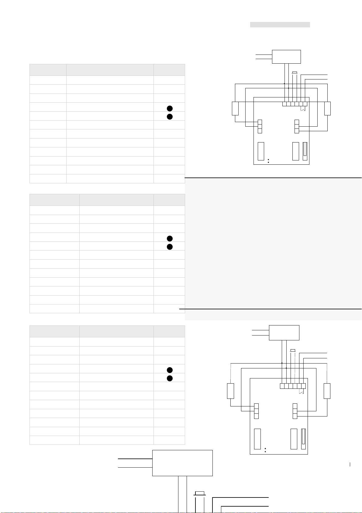
TECHNICAL SPECIFICATIONS
. Operating voltage 12 V DC : -8% to +20%
. Operating voltage 12V AC : +15%
. Consumption at rest < 5mA
. Consumption maximum <100mA
. Protection IP43/5
. Operating temperature: -20°C to +70°C
. Relay : 2 relays N/O & N/C contact 2 amp @ 24V
. 1 tamper switch
. 1 yellow LED activated : - Key-in
- Programming mode
- Data error in programming mode
. 1 green LED lights on when relay 1 is activated
. 1 red LED lights on when relay 2 is activated
. Jumper to reset the keypad
. 1 master code and 5-digit user code
. EEPROM memory storage
. Security keypad time delay
. Request to exit input for relay 1
FACTORY DEFAULT VALUES
This keypad is set with the factory default values
Code 1 : 11111 EXIT RELAY 1 momentary output time 1 second
Code 5 : 22222 EXIT RELAY 2 momentary output time 1 second
Code 0 : 00000 Master Code
SETTING A NEW MASTER CODE
Enter the master code 00000 twice. The yellow LED lights on.
Press “0” and then the new 5-digit master code, the yellow LED lights off during 1 second that the new master code
has been saved.
Press the “” key to exit from the programming mode, the yellow LED lights off.
SETTING THE USER CODES
Enter the master code twice, the yellow LED lights on.
Enter the user number from 1 to 8, then the 5-digit code, the yellow LED lights off during 1 second.
Press on the key to exit from the programming mode, or another user number, or 9 or to enter a time delay.
* Each time you key-in the LED lights off to indicate the validation of the key.
* Keypad: From “0” to “9” and “”; “” (except first digit)
* The yellow LED blinks when a data error occurs in programming mode
The master code can’t be use as door opening code
SETTING TIME DELAY
Enter the master code twice.
The yellow LED lights on
Press “9” for time delay of relay 1
Press “” for time delay of relay 2
Enter “00” for a latched output
“01” to “99” for a momentary output time
The yellow LED lights off during 1 second.
Press the “” key to exit from the programming mode, 1 to 8 to enter a user code, 9 or “” to enter a time delay.
* Each time you key-in, the LED lights off to indicate the validation of the key.
DELETING A USER CODE
Enter the master code twice, The yellow LED lights on.
Enter a user number from 1 to 8 according to the user code to delete.
Press the “” key, the yellow LED lights off during 1 second.
Press the “” key to exit from the programming mode, the yellow LED lights off.
C2R
English

G0301FR0145V01 Ed : 0799 English
4
USER CODE GROUPS
GROUP 1 : From 1 to 4 RELAY 1 Green LED
GROUP 2 : From 5 to 8 RELAY 2 Red LED
* A user code can be programmed into 2 groups to control simultaneously the 2 relays.
SECURITY TIME DELAY
. Key-in keypad delay: 10 seconds maximum
. Programming mode exit delay: 60 seconds maximum
. Lockout delay: 30 seconds
GENERAL RESET
. Cut the power supply of the keypad
. Short- circuit with the jumper.
. Put the power supply back for about 1 second. Remove the jumper
. The keypad is reset to the factory default values.
NOTE
Each time you key-in, the LED lights off during 0.1 second to indicate the validation of the key.
After 6 incorrect code, the keypad locks out during 30 seconds.

G0301FR0145V01 Ed : 0799 Italiano
5
Ed: 0497
SPECIFICHE TECNICHE
. Alimentazione 12 V DC : -8% to +20%
. Alimentazione 12V AC : +15%
. Consumo a riposo < 5mA
. Consumo massimo <100mA
. Protezione IP43/5
. Temperatura di funzionamento: -20°C to +70°C
. Relè : 2 relè N/O & N/C contatto da 2 amp @ 24V
. 1 tamper switch
. 1 LED giallo attivato : - Inserimento codice-
- Programmazione
- Dato sbagliato in modalità programmazione
. 1 LED verde si accende quando il relè 1 è attivo
. 1 LED rosso si accende quando il relè 2 è attivo
. Jumper per il reset dei codici
. 1 codice master di 5-cifre
. EEPROM per l’immagazzinamento dei dati.
. Security keypad time delay
. Un pulsante di richiesta uscita per il relè 1
Valori di DEFAULT
Questa tastiera a i seguenti valori preimpostati
Code 1 : 11111 USCITA RELE’ 1 relè pilotato per 1 secondo
Code 5 : 22222 USCITA RELE’ 1 relè pilotato per 1 secondo
Code 0 : 00000 Codice master
IMPOSTAZIONE CODICE MASTER
Inserire il codice master 00000 due volte.Il led giallo si accende.
Premere “0” e il codice Master nuovo (5 cifre),il LED giallo si spegne per 1 secondo
ed il codice nuovo è memorizzato.
Premere “” per uscire dalla programmazione , il LED giallo si spegne.
IMPOSTAZIONE DEI CODICI UTENTE
Inserire il codice master due volte.Il led giallo si accende.
Inserire il numero utente da 1 a 8, e digitare 5cifre del codice, il LED giallo si spegne per un secondo.
Premere il tasto per uscire dalla programmazione, o premete il tasto 9 o per entrare nella programmazione
dei ritardi.
Ogni durata Lei chiave-in le luci Condotte via indicare la convalidazione della chiave.
* Ogni volta che si pigia un tasto valido il LED si spegne per convalidare il tasto.
* Tasti da “0” a “9” e “” ; “” ( eccetto come primo )
* Il LED giallo lampeggia qundo c’è un inserimento dei dati in programmazione.
Il codice master non può essere usato per aprire le porte.
Impostazione ritardi
Inserire il codice master due volte
Il LED giallo si accende
Premere “9” per impostazione dei ritardi sul relè 1
Premere “” per impostazione dei ritardi sul relè 2
Digitare “00” per avere un latche output
“01” to “99” per una chiusura momentanea dell’output
Il LED giallo si spegne per un secondo.
Premere il tasto “” per uscire dalla programmazione, da 1 a 8 per codici utente,9 o
“” per entrare nella programmazione dei ritardi.
* Ogni volta che si pigia un tasto valido il LED si spegne per convalidare il tasto.
C2R
italiano

G0301FR0145V01 Ed : 0799 Italiano
6
DELETING A USER CODE
Inserire il codice master due volte
Il LED giallo si accende
Inserire il numero utente da 1 a 8 in base al codice da cancellare.
Premere il tasto “”,il LED si spegne per un secondo.
Premere il tasto “”per uscire dalla programmazione il LED si spegne.
USER CODE GROUPS
GROUPPO 1 : Da 1 a 4 RELE’ 1 Verde LED
GROUPPO 2 : Da 5 a 8 RELE’ 2 Rosso LED
* Un codice utente può essere programmato nei due gruppi per ottenere l’apertura simultanea dei due relè.
Ritardo di siqurezza.
. Ritardo inserimento cifre: 10 secondi massimo
. Uscita dalla programmazione dopo inattività : 60 secondi massimo.
. Ritardo di chiusura: 30 secondi
RESET GENERALE
1 Togliere corrente
2 Chiudere il jumper.
3 Dare corrente dopo 1 secondo togliere il jumper
4 La tastiera è ritornata con le impostazioni di default.
NOTE :
Ogni volta che viene premuto un tasto il LED si spegne per 0,1 Secondi.
Dopo 6 codici sbagliati , la resterà inattivo per 30 ssecondi.

G0301FR0145V01 Ed : 0799 Français / English /Italiano
7
RACCORDEMENT/WIRING:
N°BORNE SIGNAL SORTIE
1 contact repos relais 1
2 commun 1
3 contact travail relais 1
4 alimentation 12V
5 alimentation 12V
6 entrée bouton poussoir 1
7 entrée bouton poussoir 1
8 contact surveillance
9 contact surveillance
10 contact repos relais 2
11 commun 2
12 contact travail 2
TERMINAL DESCRIPTION OUTPUT
1 N/C contact 1
2 Common 1
3 N/O contact 1
4 Power supply 12V
5 Power supply 12V
6 Request to exit input 1
7 Request to exit input 1
8 Tamper switch output
9 Tamper switch output
10 N/C contact 2
11 Common 2
12 N/O contact 2
TERMINAL N SIGNAL OUTPUT
1 Contatto N/C 1
2 Comune 1
3 Contatto N/O 1
4 Alimentazione12V
5 Alimentazione12V
6 Pulsante uscita 1
7 Pulsante uscita 1
8 Tamper switch output
9 Tamper switch output
10 Contatto N/C 2
11 Comune 2
12 Contatto N/O 2
3
5
8
9
12
11
10
1
2
4
RL2
RL1
Alimentazione
12 V
DC or AC
115V AC
STRIKE 1
STRIKE 2
Allarme
T
C
R
R
C
T
6
7
PB
jumper
3
5
8
9
12
11
10
1
2
4
RL2
RL1
ALIMENTATION
12 V
DC ou AC
230V AC
GACHE 1
GACHE 2
ALARME
T
C
R
R
C
T
6
7
BP
picots
ALIMENTATION
12 V
DC ou AC
230V AC
ALARME
BP

G0301FR0145V01 Ed : 0799 Français / English /Italiano
8
PROTECTION :
This product comes with 1 varistors.
They must be directly installed on every strike.
The varistors will remove all interference or electromagnetic fields
caused by the strike coil.
PROTECTION :
Cet appareil est fourni avec 1 varistance. Celle-ci doit
être montée directement sur les bornes de la gâche
connectée.
La varistance supprimera tous les parasites ou champs
électromagnétiques causés par la bobine de la gâche
(effet de self).
PROTECTION
Questo prodotto è consegnato con due varistori da montare direttamente
sui morsetti dell’apriporta (magnete, motore,…) comandato
dall’apparecchiatura.
Se l’apparecch io funziona con più apriporta, ciascuno deve essere
munito di varistore.
Il varistore limita le sovratensioni provocate dall’avvolgimento
dell’apriporta effetto di autoinduzione
Table of contents
Languages:
Other CDVI Keypad manuals

CDVI
CDVI PROMI E Quick start guide

CDVI
CDVI KCIN User manual

CDVI
CDVI GALEO/W User manual

CDVI
CDVI GALEO/W User manual

CDVI
CDVI SUBLIM User manual

CDVI
CDVI GALEO 4.0 - Bluetooth User manual

CDVI
CDVI Galeo 2 User manual

CDVI
CDVI GALEO 4.0 - Bluetooth User manual

CDVI
CDVI PROFIL 100 EC User manual

CDVI
CDVI DG1 Quick start guide