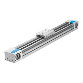
MS6-SV-...-C MS6N-SV-...-C
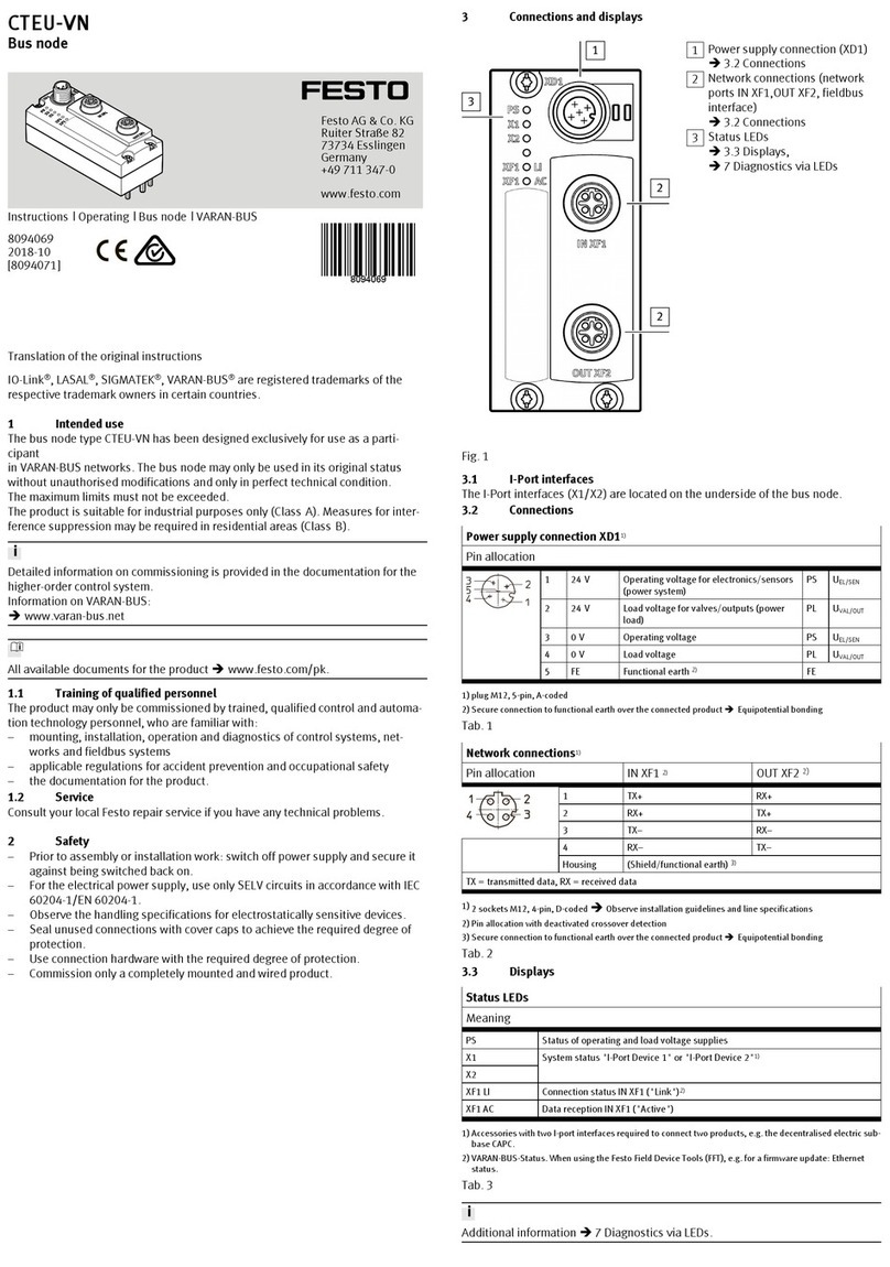
Pneumatic port 2 Port sizes è 4.2 Product variants
Pneumatic port 3 G 3/4 NPT 3/4
Type of mounting –In-line installation
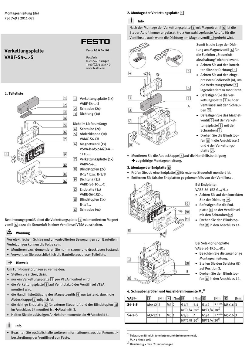
–with accessories
Mounting position Any
Design Piston slide
Actuation type Electric
Exhaust function Cannot be throttled
Type of control Pilot-controlled
Valve function –3/2-way valve, closed, monostable
–Adjustable soft-start function
Operating medium Compressed air to ISO 8573-1:2010 [7:4:4] and inert
gases
Information on the oper-
ating medium
Lubricated operation possible, in which case lubricated
operation will always be required
Manual override at the soft-
start/quick exhaust valve
Detenting/self-reset
Manual override at the pilot solenoid valve
-10V24, -10V24F Non-detenting, actuation from above
-10V24P Non-detenting/detenting, actuation from above
-10V24C/D/E No manual override
-V24, -V24P, -V110, -V230 Non-detenting/detenting, actuation from front
Operating pressure p1
-10V24, -10V24P/C/D/E/F [MPa] 0.3 … 1
[bar] 3 … 10
[psi] 43.5 … 145
-V24, -V24P, -V110, -V230 [MPa] 0.3 … 1.8
[bar] 3 … 18
[psi] 43.5 … 261
Characteristic flow rate values
Pressure switching point Adjustable è 12.3 Pressure switching point (PSP)
Pressurisation flow rate Adjustable via main flow control valve (FCV) è 12.2 Pres-
surisation flow rate
Standard nominal flow rate
1 } 2
[l/min] 5700
Standard nominal flow rate
2 } 3
[l/min] 7600
measured at p = 0.6 MPa (87 psi; 6 bar) with silencer
U-3/4-B
Electrical connection
-10V24, -V24, -10V24C Plug, 2-pin, in accordance with EN 175301-803, type C
-V24P, -10V24P/D/E/F M12x1, 4-pin, in accordance with EN 61076-2-101
-V110, -V230 Plug, 3-pin, in accordance with EN 175301-803, type C
Coil characteristics
-10V24, -10V24P/C/D/E/F 24 V DC, 1.8 W
-V24, -V24P 24 V DC, 1.5 W
-V110 110 V AC, 50/60 Hz, pick-up power 3 VA, holding power
2.4 VA
-V230 230 V AC, 50/60 Hz, pick-up power 3 VA, holding power
2.4 VA
Permissible voltage fluctuations
-10V24, -10V24P/C/D/E/F,
-V24, -V24P, -V110
[%] ±10
-V230 [%] –14 … +10
Operating and environmental conditions
Ambient temperature [°C] 0 … +60 (0 … +50 with pressure sensor)
Temperature of medium [°C] 0 … +60 (0 … +50 with pressure sensor)
Storage temperature [°C] –10 … +60 (0 … +50 with pressure sensor)
Shock resistance Shock test with severity level 2 in accordance with
FN 942017-5 and EN 60068-2-27
Vibration resistance Transport application test with severity level 2 in accord-
ance with FN 942017-4 and EN 60068-2-6
Sound pressure level1) [dB(A)] 93
Degree of protection IP65 with plug socket
Weight
without silencer [g] 886
with silencer U-3/4-B [g] 1006
Materials
Housing Die-cast aluminium
Cover top/bottom PA
Piston rod High-alloy steel
Seals NBR
1) maximum A-weighted impulse sound pressure level at the loudest measuring point during exhaust of the
valve with silencer U-3/4-B
Tab. 7: General technical data
Type of severity level (SL)
Vibration load
Frequency range [Hz] Acceleration [m/s2] Deflection [mm]
SL1 SL2 SL1 SG2 SL1 SL2
2 … 8 2 … 8 – – ±3.5 ±3.5
8 … 27 8 … 27 10 10 – –
27 … 58 27 … 60 – – ±0.15 ±0.35
58 … 160 60 … 160 20 50 – –
160 … 200 160 … 200 10 10 – –
Shock load
Acceleration [m/s2] Duration [ms] Shocks per direction
SL1 SL2 SL1 SL2 SL1 SL2
±150 ±300 11 11 5 5
Continuous shock load
Acceleration [m/s2] Duration [ms] Shocks per direction
±150 6 1000
Tab. 8: Type of severity level (SL)
12.2 Pressurisation flow rate
Flow rate qn as a function of the number of revolutions n of the main flow control
valve (FCV) è Fig. 6.
p1 = 0.6 MPa (6 bar; 87 psi)
Fig. 6: Flow diagram
12.3 Pressure switching point (PSP)
A slow pressure build-up of outlet pressure p2 is achieved with the main flow
control valve located in the cover. If the outlet pressure p2 has reached the
switch-through pressure, the valve opens and the complete operating pressure p1
is applied at the output port.
The pressure switching point can be set by turning the adjusting screw for the
pressure switching point.
Fig. 7: Pressure switching point
12.4 Exhaust time
The following table shows the exhaust time in normal operation (N) with silencer
U-3/4-B at various volumes and operating pressures.
Normal operation N Exhaust time [s]
Operating pres-
sure
[MPa] 0.3 0.6 1 1.8
[bar] 3 6 10 18
[psi] 43.5 87 145 261
Exhaust to [MPa] 0.1 0.05 0.1 0.05 0.1 0.05 0.1 0.05
[bar] 1 0.5 1 0.5 1 0.5 1 0.5
[psi] 14.5 0.725 14.5 0.725 14.5 0.725 14.5 0.725
Volume [l] 2 0.4 0.5 0.5 0.6 0.6 0.7 0.7 0.8
10 0.6 0.8 0.9 1.1 1.1 1.3 1.4 1.6
20 0.9 1.3 1.5 1.9 1.9 2.9 3.5 3.0
40 1.5 2.2 2.6 3.4 3.4 4.3 4.5 5.5
Tab. 9: Exhaust time
