manuals.online logo
Brands
  1. Home
  2. •
  3. Brands
  4. •
  5. LuxaFlex
  6. •
  7. Window Blind
  8. •
  9. LuxaFlex EVO MagnaTrack User manual

LuxaFlex EVO MagnaTrack User manual

EVO MagnaTrack
Installation Manual
2 | P a g e
SAFETY & WARNING ADVICE
A minimum of 2 people is necessary for proper installation.
Installation fixings will NOT be supplied with any of the Evo Awning series.
Please refer to fixing section. Each installation should be assessed on a case by case
scenario.
WARNING! –The brackets must be fixed solidly to a substantial surface. Hollow bricks or
foam products are not suitable. Brick veneer surfaces require at least 2 courses of
brickwork above the bracket and 2 courses below.
General Advice: The electrical data is shown on the label of electric operating
awnings.
TOOLS REQUIRED
The following tools are required for installation:
•Level
•Battery Drill
•Screwdrivers
•Hammer Drill
•Drill Bits
•Rubber Mallet
MAGNET CARE & HANDLING
•The magnetic field affects pacemakers, so they need to be kept outside this range
•Do not cut the magnets. They will blunt the cutting blade or shatter causing serious
injury
•Do not powder coat the magnets. The baking temperatures in the process remove
the magnetic field
•Temperatures over 130˚c remove the magnetic field
•The magnets have high forces which will cause pinch points
•The magnets are brittle and will chip/break easily. For instance, if dropped from a
workbench or released to attract together from about 75mm apart
•If the chrome plating on the surface is chipped or removed severe corrosion will
occur
3 | P a g e
MAGNATRACK EXPLODED DIAGRAM
No
Part Code
Description
5
510121
UNIVERL ZAMACK BRT & LOCK RING
6
7
8
9
10
709848
ALTUS 50 RTS 25/17 MOTOR
11
12
709916
709915
CROWM 60MM OCTAGONAL TUBE
WHEEL 60MM OCTAGONAL TUBE
13
44.010.XXX
STANCE FIBREGLASS SKIN
44011.XXX
44.012.XXX
14
42.421.855
POLY-ABS SPLINE TUBE 6mm
15
52.000.063
UNIVERSAL BRACKET 74MM S-STEEL
16
52.001.XXX
4MM KEDER SPLINE
17
52.002.000
25MM HBOX FELT
18
52.003.XXX
2” LONG NEODYIUM MAGNET
19
52.005.000
60MM OCTAGONAL TUBE (X2 PER BLIND IF OVER 1072MM WIDE)
20
52.006.000
60MM OCTAGONAL TUBE IDLER END ASSEMBLY (15.5MM SQR SHAFT
21
52.005.000
60MM OCTAGONAL TUBE IDLER END ASSEMBLY (HOUSING)
22
52.006.000
52.007.063
60MM OCTAGONAL TUBE IDLER END ASSEMBLY (BEARINGS)
23
60MM OCTAGONAL TUBE IDLER END ASSEMBLY (EXTERNAL CIRCLIPS)
24
60MM OCTAGONAL TUBE IDLER END ASSEMBLY (EXTERNAL CIRCLIPS)
25
16MM SQR IDLER END PLATE (R-CLIP)
26
16MM SQR IDLER END PLATE
27
52.007.063
52.008.XXX
52.009.000
16MM SQR IDLER END PLATE (SCREWS)
28
BOTTOM BAR
29
BOTTOM BAR PROBE (HOUSING BLOCK)
30
52.008.XXX
BOTTOM BAR PROBE (KEDER SCREWS)
31
52.009.000
52.010.000
52.001.030
BOTTOM BAR PROBE (SECURING SCREWS)
32
1” LONG NEODYMIUM MAGNET
33
BOTTOM RAIL WEIGHTS
34
52.012.000
BOTTOM BAR FELT
35
52.013.XXX
MAGNATRACK GUIDE
36
52.014.XXX
MAGNATRACK COVER
38
52.016.XXX
MAGNATRACK HOUSING
39
52.017.XXX
MAGNATRACK END CAP (MAIN BODY)
40
52.017.XXX
MAGNATRACK END CAP (SCREWS X8)
39
52.017.XXX
M150 HEADBOX END CAP (STD SCREWS X8)
41
42
52.018.XXX
52.020.XXX
MAGNATRACK BUMPER
M150 HEADBOX (BACK PLATE)
43
52.021.XXX
M150 HEADBOX COVER FRONT
44
52.022.XXX
M150 HBOX END CAP (REVEAL SCREW)
45
52.021.XXX
M150 HBOX END CAPS
46
52.027.000
4” DONUT (75MM LONG 4” TUBE)
47
4” DONUT (SECURING SCREWS)
48
52.029.XXX
52.029.XXX
MAGNATRACK FUNNEL (MAIN BODY)
49
MAGNATRACK FUNNEL (GRUB & SCREWS)
50
52.030.000
VELCRO
4 | P a g e
FIXINGS
Due to possible differences in specification, application and interpretation of results,
users must make their own evaluation of the product to determine the suitability of
fixings and their intended use.
ITEM
TITLE
DESCRIPTION
Decking Screws
12g x 65mm (minimum)
Used to fix channels
Inside or Face Fit
Roofing & Cladding
Hex Head (Buildex)
12g x 65mm (minimum)
Available in Metal or Timber thread
Used to fix universal
brackets
Ramplug/Green Plug (Ramset)
65mm Length
Used to fit to brick or
concrete
Dyna Bolt (Ramset)
6mm x 40mm
Used to face fix
channels
Dyna Bolt (Ramset)
8mm x 50mm
Used to fix universal
brackets
5 | P a g e
OPEN ROLLER INSTALLATION
•Step 1 - Mark fixing holes for the first bracket
•Step 2 - Drill fixing holes
•Step 3 - Install the first bracket
•Step 4 - Measure overall width
•Step 5 - Repeat steps 1,2 & 3 for the second bracket
STEP 1
Mark fixing holes for first bracket based on the finished fitting scenario below.
Note: The scenarios are for motor LHS, Idle End RHS.
Minimum spacing required for recess fit.
In ceiling fit applications, the bracket needs to be 27 mm to vertical wall so the evo
MagnaTrack Channel is in the correct position and 102mm tube with skin does not rub
drive
DRIVE END
IDLE END
SCENARIO 1 - FACE FIT (FF)
SCENARIO 2 –CEILING FIT ON FACE (CFF)
SCENARIO 3 –FACE FIT IN REVEAL (FFR)
SCENARIO 4 –CEILING FIT IN REVEAL (CFR)
6 | P a g e
STEP 2
•Select fasteners to mount the blind based on the substrate it is being fixed to.
•Drill fixing holes for the first bracket based on the fasteners selected from the fixing
table.
STEP 3
•Check the orientation of the motor/idle plates are correct on the universal
bracket.
•Fix the first bracket in place using the fasteners selected above, ensure the
bracket is straight using a spirit level. If required pack out the bracket.
STEP 4
•Measure the overall width to position the 2nd bracket and ensure the tube
assembly will fit between the brackets.
STEP 5
•Repeat steps 1 to 3 for the second bracket.
7 | P a g e
HEADBOX INSTALLATION
•Step 1 - Open the headbox
•Step 2 - Holes on headbox backplate
•Step 3 - Positioning and securing the headbox through the brackets.
Always secure the headbox back panel/end caps through the installation
brackets
•Step 4 - Front cover retainment in reveal fits
STEP 1
Open the headbox front cover by removing
the screw in fig H1 shown below, note for
reveal applications this screw is no longer
required. (Hbox felt not pictured)
STEP 2
•Select fasteners to mount the blind based on the substrate it is being fixed to.
•Mark and drill the clearance holes on the headbox back plate or end caps for the
74mm universal bracket and electrical cable based on the finished fitting scenario
below and the fasteners selected above.
Mark and drill additional clearance holes through the headbox back plate at intervals
of (650 to 1750mm). Ensure the clearance hole for the electrical cable aligns with a
suitable position on the installation surface
Apply protection around clearance hole for electrical cable from motor and ensure
the clearance hole for the electrical cable is large enough to fit the plug through with
the protective coating in place.
Always secure the headbox back plate/end caps through the Installation brackets.
8 | P a g e
STEP 2 - CONT
DRIVE END
IDLE END
SCENARIO 1 - FACE FIT (FF)
SCENARIO 2 –CEILING FIT ON FACE (CFF)
SCENARIO 3 –FACE FIT IN REVEAL (FFR)
SCENARIO 4 –CEILING FIT IN REVEAL (CFR)
9 | P a g e
STEP 3
•Check the orientation of the motor/idle plates are correct on the universal
brackets (FIG H2).
•Mark a fixing hole on installation surface through respective hole on headbox for
the motor side bracket.
•Drill a fixing hole on installation surface through respective hole on headbox based
on the fasteners selected for the motor side bracket.
•Secure a fastener in the motor side bracket to hold one side of the headbox.
•Mark a fixing hole on installation surface through respective hole on headbox for
the idle side bracket. Ensure headbox is level and straight using a spirit level.
•Drill a fixing hole on installation surface through respective hole on headbox based
on fasteners selected for the idle side bracket.
•Secure a fastener in the idle side bracket to hold headbox.
•Scenario 2 (CFF) may need packers between the headbox back plate and
installation surface to level the headbox.
•Scenario 3 (FFR) and 4 (CFR) may need packers between the headbox end caps
and installation surfaces to centre the headbox in reveal.
•When the headbox is centred and level, mark, drill and secure the remaining fixing
points as per steps B - G above.
•Secure the headbox back plate at the additional locations through the headbox
as noted in step 2 (Headbox Installation)
•Mark and drill the clearance hole on the installation surface for the motor
electrical cable. Take care not to damage the protection around the hole from
step 2 (Headbox Installation).
STEP 4
5mm hole is to be drilled in the front cover for reveal applications. Location of the hole
is shown in fig H3.
FIG H2
10 | P a g e
SIDE CHANNEL & BLIND INSTALLATION
FLOWCHART
Section 1.0
Are channels to be mounted on face or reveal?
FACE FIT
1. Section 1.1 - Install roller tube, prepare Evo MagnaTrack channels
2. Section 2.1 - Assemble the bottom bar
3. Section 3.1 - Install Evo MagnaTrack channels and front cover
4. Section 4 - Donut adjustment and probe securing
5. Section 5 - Assemble headbox (if applicable)
REVEAL FIT
1. Section 1.2 - Is reveal out of square over 20mm?
2. NO - Section 1.2.1 - Install channels and front cover
YES - Section 1.2.2 - Install U-Channels and front cover
3. Section 2.2 - Install roller tube
4. Section 3.2 - Install bottom bar
5. Section 4 - Donut adjustment and probe securing
6. Section 5 - Assemble headbox (if applicable)
11 | P a g e
SIDE CHANNEL & BLIND INSTALLATION METHOD
SELECTION
STEP 1
Open the headbox
The blind installation of the side channels varies depending on the fitting application.
Refer to the diagrams below to determine the installation method to follow.
Face Fit - go to Section 1.1
Reveal Fit - go to Section 1.2
STEP 2
Face Fit - go to Section 1.1
Reveal Fit - go To Section 1.2
12 | P a g e
FACE FIT APPLICATION
13 | P a g e
SECTION 1.1: FACE FIT - INSTALLATION OF
ROLLER TUBE WITH FABRIC
STEP 1
Install the roller tube on the universal brackets.
•Drill any additional holes before putting up tube assembly. e.g. electrical cable
outlets.
•While installing the drive end of the tube be sure to align the electrical cables
with the holes and don’t pinch the cables between the motor head and the
bracket
Scenario 1:
60mm octagonal tube installation (with 102mm main tube, skin is not shown)
INSERT DRIVE END INTO UNIVERSAL
BRACKET FIRST
INSERT IDLE END INTO UNIVERSAL BRACKET
SECOND
THEN INSTALL THE RESPECTIVE RETAINMENT PINS/CLIPS
Scenario 2:
78mm tube installation (skin and bottom rail is not shown)
INSERT DRIVE END INTO UNIVERSAL
BRACKET FIRST
INSERT IDLE END INTO UNIVERSAL BRACKET
SECOND
THEN INSTALL THE RESPECTIVE RETAINMENT PINS/CLIPS
14 | P a g e
STEP 2
Prepare Evo MagnaTrack channels.
Remove front cover by inserting a flat head screwdriver under the end cap and lifting
out. Then gradually work along the length of the extrusion. Forcing off the front cover.
•Select fasteners based on what substrate channels are being attached to.
•Depending on the fasteners chosen, this dictates the horizontal position of the
holes (See FIG J1).
•Mark and drill the clearance holes for the fasteners as required from the
diagrams below.
NOTES:
•Wood screws to have at least 65mm embedment.
•Masonry screws to have at least 40 mm embedment.
•If side channels need to be trimmed, perform this at the
bottom end of the channel.
15 | P a g e
SECTION 2.1: FACE FIT - ASSEMBLE BOTTOM BAR
STEP 1
Connect motor to power and lower the skin to waist height from ground.
STEP 2
Feed bottom rail onto skin.
•Use silicon spray to lubricate the bottom rail and bottom of fabric groove to
reduce friction.
•Slide the bottom rail onto the fabric.
•The keder tail is folded up so it is out of the way during this process.
•Stop at the spline.
NOTE: THE BOTTOM RAIL IS HEAVY. BOTTOM RAIL MUST BE SUPPORTED WHILE FEEDING
BOTTOM RAIL TO ENSURE NO DAMAGE TO THE FABRIC SKIN.
16 | P a g e
STEP 3
Fasten probes onto the keder.
•Start on Idle side.
•Remove the screws from the probe.
•Fold the keder out of the way.
•Insert the probe into the bottom rail.
•Release the keder and slide the probe out of the bottom rail while guiding the
keder flaps into the slot.
•Ensure the flap of the keder is fully inside the slot on the probe before securing
(fig B1).
•Fasten the probe screws into the keder flaps (fig B2).
•Slide the bottom rail over the probe and screws 12-22 mm so the probe can be
installed on the other side, then repeat the process (fig B3).
Note the brush will also slide in the bottom rail.
•Slide bottom rail back to the middle position once both probes are located
inside the bottom rail and secured to the keder.
17 | P a g e
SECTION 3.1: FACE FIT - INSTALLATION OF EVO
MAGNATRACK
STEP 1
Feed the channels with the screen guide inside onto the skin.
Position with headbox
•Pull skin out from the wall (fig F1)
•Feed the keder into the
funnel/screen guide notch (fig F2)
•Slide the channel up to butt up to
the headbox (fig F3). For scenarios
with no headbox refer to fig F4, F5
& F6.
This is extremely important for correct
operation. If the side channel is
mounted too low the bottom rail will
come out and the skin will no longer
be retained.
Position with no headbox (brackets on face)
18 | P a g e
Position with no headbox (brackets on ceiling)
STEP 2
Align and secure the side channels.
STEP 3
Repeat steps Section (3.1) 1-2 for the other side.
19 | P a g e
REVEAL FIT INSTALLATION
20 | P a g e
SECTION 1.2: REVEAL FIT PREPARATION
STEP 1
Remove screen guide as per below schematic.
STEP 2
Go to section 1.2.1 for reveal fit

Other LuxaFlex Window Blind manuals

LuxaFlex Timber Venetians User manual

LuxaFlex

LuxaFlex Timber Venetians User manual

LuxaFlex Aluminium Venetians User manual

LuxaFlex

LuxaFlex Aluminium Venetians User manual

LuxaFlex Roman Series User manual

LuxaFlex

LuxaFlex Roman Series User manual

LuxaFlex SimpleFit Plisse User manual

LuxaFlex

LuxaFlex SimpleFit Plisse User manual

LuxaFlex Country Woods Venetians User manual

LuxaFlex

LuxaFlex Country Woods Venetians User manual

LuxaFlex Skylight Series User manual

LuxaFlex

LuxaFlex Skylight Series User manual

LuxaFlex LiteRise User manual

LuxaFlex

LuxaFlex LiteRise User manual
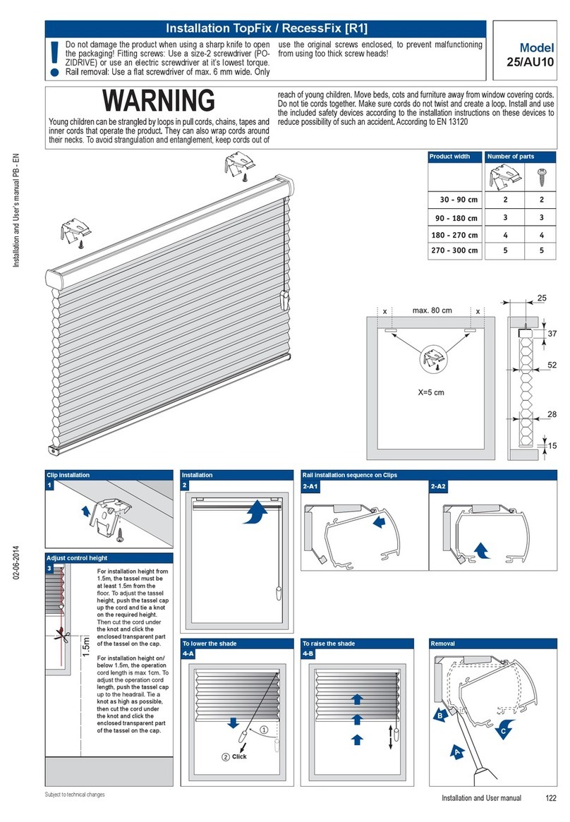
LuxaFlex Twist User manual

LuxaFlex

LuxaFlex Twist User manual

LuxaFlex Silhouette Shades User manual

LuxaFlex

LuxaFlex Silhouette Shades User manual

LuxaFlex 2106/56 User manual

LuxaFlex

LuxaFlex 2106/56 User manual

LuxaFlex RecessFix User manual

LuxaFlex

LuxaFlex RecessFix User manual
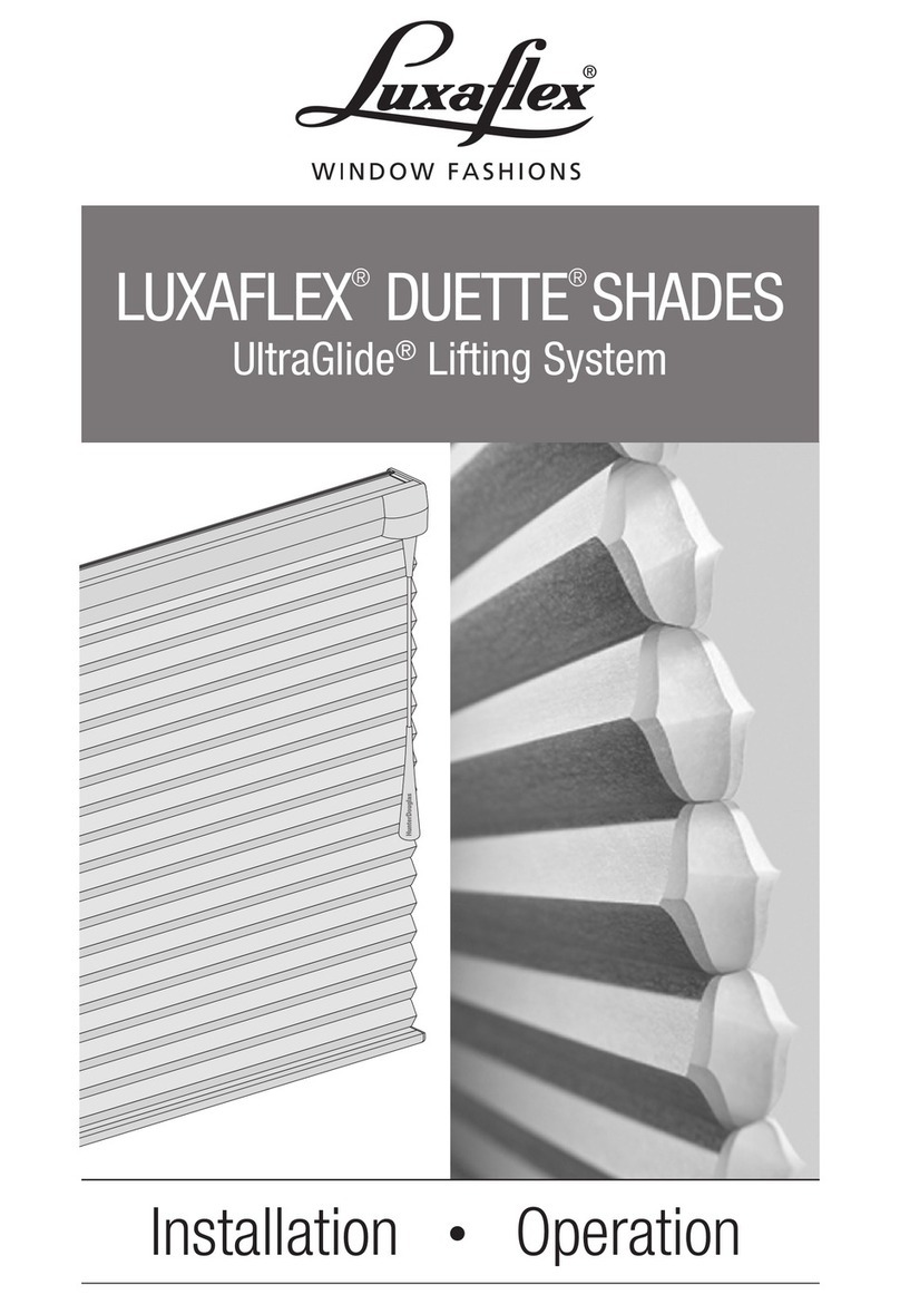
LuxaFlex Super Nova User guide

LuxaFlex

LuxaFlex Super Nova User guide

LuxaFlex Silhouette Shadings User manual

LuxaFlex

LuxaFlex Silhouette Shadings User manual

LuxaFlex Twist Series User manual

LuxaFlex

LuxaFlex Twist Series User manual

LuxaFlex Duette Honeycomb Shades Parts list manual

LuxaFlex

LuxaFlex Duette Honeycomb Shades Parts list manual

LuxaFlex Venetian Series User manual

LuxaFlex

LuxaFlex Venetian Series User manual

LuxaFlex 410 User manual

LuxaFlex

LuxaFlex 410 User manual

LuxaFlex Venetian Series User guide

LuxaFlex

LuxaFlex Venetian Series User guide

LuxaFlex EasyRise Duette Parts list manual

LuxaFlex

LuxaFlex EasyRise Duette Parts list manual

LuxaFlex LUMINETTE Dimensional drawing

LuxaFlex

LuxaFlex LUMINETTE Dimensional drawing

LuxaFlex Roller blinds series User manual

LuxaFlex

LuxaFlex Roller blinds series User manual

LuxaFlex Timber User manual

LuxaFlex

LuxaFlex Timber User manual

LuxaFlex Wood Essence Blinds User manual
LuxaFlex

LuxaFlex Wood Essence Blinds User manual

LuxaFlex M25T User manual

LuxaFlex

LuxaFlex M25T User manual

Popular Window Blind manuals by other brands

PLISSEEABWERK P1615 Assembly instruction

PLISSEEABWERK

PLISSEEABWERK P1615 Assembly instruction

Isotra VS 2 Assembly manual

Isotra

Isotra VS 2 Assembly manual

Alpha Motors WSERD30B Guide

Alpha Motors

Alpha Motors WSERD30B Guide

weinor VertiTex II Maintenance instructions and directions for use

weinor

weinor VertiTex II Maintenance instructions and directions for use

Velux Solar SSS Important information

Velux

Velux Solar SSS Important information

B&C Honeycomb installation guide

B&C

B&C Honeycomb installation guide

Horrex UCS curved installation manual

Horrex

Horrex UCS curved installation manual

GAPOSA XQ5 Programming Quick Guide

GAPOSA

GAPOSA XQ5 Programming Quick Guide

Benthin RS02 manual

Benthin

Benthin RS02 manual

Isotra PL 32 D Assembly manual

Isotra

Isotra PL 32 D Assembly manual

HunterDouglas PowerView manual

HunterDouglas

HunterDouglas PowerView manual

HunterDouglas PowerView M40T instructions

HunterDouglas

HunterDouglas PowerView M40T instructions

HunterDouglas Silhouette A Deux Installation operation care

HunterDouglas

HunterDouglas Silhouette A Deux Installation operation care

HunterDouglas 5-216 Installation instruction

HunterDouglas

HunterDouglas 5-216 Installation instruction

HunterDouglas Standard Hardware System Installation operation care

HunterDouglas

HunterDouglas Standard Hardware System Installation operation care

HunterDouglas Pirouette PowerView+ Gen 3 Automation Installation operation care

HunterDouglas

HunterDouglas Pirouette PowerView+ Gen 3 Automation Installation operation care

HunterDouglas Sonnette installation guide

HunterDouglas

HunterDouglas Sonnette installation guide

HunterDouglas Silhouette Duolite UltraGlide instruction manual

HunterDouglas

HunterDouglas Silhouette Duolite UltraGlide instruction manual

manuals.online logo
manuals.online logoBrands
  • About & Mission
  • Contact us
  • Privacy Policy
  • Terms and Conditions

Copyright 2025 Manuals.Online. All Rights Reserved.