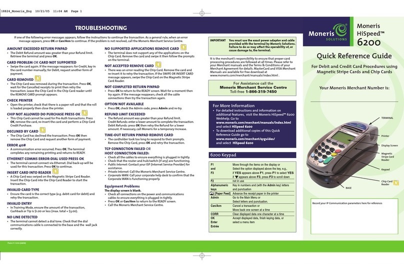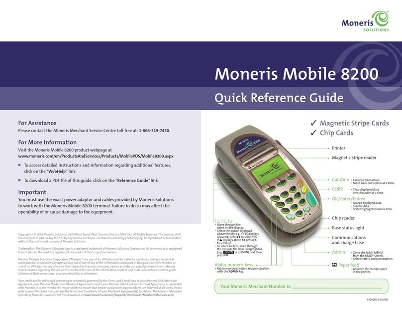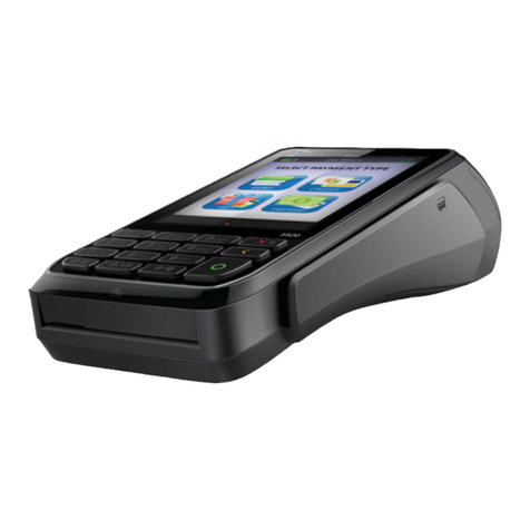
1110 MONERIS® ICT250: REFERENCE GUIDE
Magic box with dial cable
p2_step1_dialcable-connect.jpg
Magic box with Ethernet cable
p2_step1_Ethernetcable-connect.jpg
Magic box with connector
p5_step5-b_connector-to-box.jpg
Power cable
p5_step5-a_powercable_2-pc.jpg
Extended paper
p4_step4_paperroll-extended.jpg
Paper roll
p4_step4_paperroll-inserted.jpg
3l, m
p4_step3-lm_panel-closed.jpg
3k
p4_step3-k_panel-closing.jpg
3j
p3_step3-j_cable-inserted.jpg
3i
p3_step3-i_cable-hovering.jpg
3g,h
p3_step3-gh_stopper-cut.jpg
3e,f
p3_step3-ef_panel-open.jpg
3d
p3_step3-d_panel-closed.jpg
3 a,b,c
p3_step3-abc_pinpad-connect.jpg
PINPAD
CABLE
Connect the external iPP320 PINpad (optional) – continued
l. Close the back panel until it snaps shut. (The PINpad
cable should be secured as it passes through the
middle opening between the closed panel and the
terminal.)
m . Go to step 4 below.
3
SETTING UP YOUR TERMINAL
Magic box with dial cable
p2_step1_dialcable-connect.jpg
Magic box with Ethernet cable
p2_step1_Ethernetcable-connect.jpg
Magic box with connector
p5_step5-b_connector-to-box.jpg
Power cable
p5_step5-a_powercable_2-pc.jpg
Extended paper
p4_step4_paperroll-extended.jpg
Paper roll
p4_step4_paperroll-inserted.jpg
3l, m
p4_step3-lm_panel-closed.jpg
3k
p4_step3-k_panel-closing.jpg
3j
p3_step3-j_cable-inserted.jpg
3i
p3_step3-i_cable-hovering.jpg
3g,h
p3_step3-gh_stopper-cut.jpg
3e,f
p3_step3-ef_panel-open.jpg
3d
p3_step3-d_panel-closed.jpg
3 a,b,c
p3_step3-abc_pinpad-connect.jpg
LATCH
CORNER
LATCHES
BACK PANEL
RUBBER STOPPER
a
c
b
PINPAD CABLE
“USB HOST”
PORT
CORNER
TABS
MIDDLE GROOVE
Connect the external iPP320 PINpad (optional)
a. Turn the PINpad over so that the back panel is facing you.
b. Plug the PINpad cable into the USB port on the PINpad
(raise the latch).
c. Fold the latch down and press to secure the cable.
d. Turn the terminal over so that the back panel is facing
you. Locate the two corner latches.
e. Grip the latches simultaneously, and then pull back to
raise the back panel.
f . Detach the panel completely.
g. If a three-pronged rubber stopper is attached, go to
step h.
If there is no stopper, go to step i.
h. Grip the stopper, and pull back until it tears off
completely (or use scissors to carefully snip it off).
i. Plug the PINpad cable into the port labelled “USB HOST”
in the terminal compartment.
j. Position the PINpad cable so that it sits securely
in the middle groove at the top of the terminal.
k. Position the back panel so that its upper two corner tabs
are slotted into the openings at the top of the terminal.
3
PINPAD
CABLE
PLUG
CONNECTOR
ADAPTOR
BOX
CPX##.##
<RS232>
###### ######
MAGIC
BOX
Connect the two-part power supply cable
a. Insert the plug connector into the adaptor box to form the
complete power cable.
b. Insert the power cable’s barrel connector into the Magic
Box’s circular port labelled with the power symbol “ ”.
c. Plug the other end of the power cable into a power source. The terminal (and
external iPP320 PINpad if attached) will power on.
Recommendations: Always plug the power cable into the power source last to
avoid power surges. Use a power bar equipped with surge protection if possible.
Do not use the power cable from your existing terminal, as it may damage your
new terminal.
Important: You must use the exact power adaptor and cables provided by Moneris
to work with the Moneris iCT250 terminal. Failure to do so may affect the
operability of, or cause damage to, the equipment.
d. Wait for the terminal to display TERMINAL SETUP
REQUIRED.
• If you attached an external PINpad, wait for it to
display the CPX version screen as shown here.
e. Go to step 5, “Install the paper roll” on page 12.
4
