manuals.online logo
Brands
  1. Home
  2. •
  3. Brands
  4. •
  5. Teknik
  6. •
  7. Indoor Furnishing
  8. •
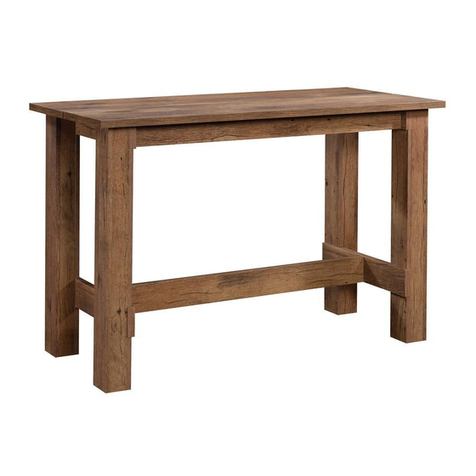
  9. Teknik Boulevard Cafe 5420667 User manual

Teknik Boulevard Cafe 5420667 User manual

Your holder for all
things awesome.
Credenza
Boulevard Cafe Collection | Model 5420667
NOTE: THIS INSTRUCTION
BOOKLET CONTAINS IMPORTANT
SAFETY INFORMATION.
PLEASE READ AND KEEP FOR
FUTURE REFERENCE.
Teknik
www.teknikoffice.co.uk
Table of Contents Assembly Tools Required
Part Identification
Hardware Identification
Assembly Steps
Safety
Hammer
Not actual size
3
4
5-28
29
No. 2 Phillips Screwdriver
Tip Shown Actual Size
Skip the power trip.
This time.
Use of a TV that is too heavy or large is hazardous. A TV that is too heavy will create a risk of a tip-over that can cause severe injury or
death. A TV that is too large for the available space might be accidentally pushed or bumped o the furniture, or subject to tip-over.
• Check the size and weight of your TV. Compare it to the diagram below – before you begin assembly!
• This Sauder unit is designed for use with televisions weighing less than 70 pounds. Never use with a TV that weighs more.
• The size of the television, front-to-back and side-to-side, must fit within the space defined in the diagram.
• Never place the front edge of the TV past the front edge of the TV support shelf (or stop molding – if equipped)
• Never allow the sides of the TV to extend past the side edges of the TV support surface.
• If the TV has a CRT picture tube, the picture tube cone may extend past the rear of the support shelf.
• Be sure to apply the warning label as instructed in the last assembly step. The label provides important safety related information.
WARNING
!
70 lbs.
70 lbs.
16-1/2"
16-1/2"
60"
60"
Page 2
Part Identification
åWhile not all parts are labeled, some of the parts will have a label or an inked letter on the edge
to help distinguish similar parts from each other. Use this part identification to help identify similar parts.
Now you know
our ABCs.
A RIGHT END (1)
B LEFT END (1)
C TOP (1)
D BACK (1)
E UPRIGHT (1)
F ADJUSTABLE SHELF (2)
G DOOR RAIL (2)
H SHELF (1)
I BOTTOM (1)
J REAR LEG (1)
K FRONT LEG (1)
L LEFT DOOR (1)
M RIGHT DOOR (1)
N FLIP UP DOOR (1)
O LEFT DRAWER SIDE (1)
P DRAWER BACK (1)
Q DRAWER BOTTOM (1)
R RIGHT DRAWER SIDE (1)
S DRAWER BRACE (1)
T DRAWER FRONT (1)
A
B
C
DE
F
F
G
G
H
I
J
K
LM
N
OP
Q
R
S
T
Page 3
Hardware Identification
åScrews are shown actual size. You may receive extra hardware with your unit.
BLACK 1/2" ALLEN HEAD SCREW - 3
20
CAM COVER CARD - 1
14
LARGE HIDDEN
CAM - 18
3SMALL HIDDEN
CAM - 6
4
WOOD
DOWEL - 29
7
BLACK 1/2" PAN HEAD SCREW - 16
23
SILVER 1/2" FLAT HEAD SCREW - 8
21 BLACK 1/2" FLAT HEAD SCREW - 8
22
BLACK 1-1/2" FLAT HEAD SCREW - 16
18
BLACK 1" FLAT HEAD SCREW - 6
19
BLACK 1-1/2" ALLEN HEAD SCREW - 6
17
ANGLED HEAD
CAM SCREW - 18
5
Angled head
HINGE - 4
13
HINGE BRACKET - 4
12
METAL PIN - 8
8
DOOR STOP - 2
10
PULL - 1
16
(EXTENSION SET SHOWN SEPARATED)
DOOR PULL - 2
15
GROMMET
WITH CAP- 2
11
STRAIGHT HEAD
CAM SCREW - 6
6
Straight head
THREADED
PIN - 2
9
1EXTENSION RAIL - 2 2EXTENSION SLIDE - 2
(Refer to the step 23 for proper
location and application)
WARNING LABEL - 1
24
522,68 22,68
70 lbs. 31,75 kg 31,75 kg
Page 4 www.sauder.com 420667
ALLEN WRENCH - 1
25
Step 1
å Assemble your unit on a carpeted floor or on the empty
carton to avoid scratching your unit or the floor.
å Push eighteen LARGE HIDDEN CAMS (3) into the
ENDS (A and B), BACK (D), UPRIGHT (E), and SHELF (H).
Arrow (18 used)
Arrow
Arrow
33
The arrow in the HIDDEN
CAM must point toward the
hole in the edge of the board.
Hole
A
B
D
E
H
Page 5
Step 2
å Fasten the HINGE BRACKETS (12) to the LEFT END (B) and
UPRIGHT (E). Use the screws in the HINGE BRACKETS.
å NOTE: Be sure to use the exact holes shown.
B
E
12
Page 6
12
Step 3
å Turn eighteen ANGLED HEAD CAM SCREWS (5) into the
ENDS (A and B), TOP (C), and UPRIGHT (E).
Angled head
5(18 used) C
A
B
E
Page 7
Step 4
å Fasten the DOOR RAILS (G) to the RIGHT END (A) and
UPRIGHT (E). Use six BLACK 1" FLAT HEAD SCREWS (19).
å Fasten the DOOR STOPS (10) to the RIGHT END (A) and
UPRIGHT (E). Use four BLACK 1/2" PAN HEAD SCREWS (23).
10
10
BLACK 1" FLAT HEAD SCREW
(6 used for the DOOR RAILS)
19
A
E
BLACK 1/2" PAN HEAD SCREW
(4 used for the DOOR STOPS
23
G
G
Page 8
Step 5
å Separate the EXTENSION SLIDES (2) from the
EXTENSION RAILS (1) as shown in the upper diagram
below. Be prepared, the parts are greasy.
å Fasten the EXTENSION RAILS (1) to the RIGHT END (A) and
UPRIGHT (E). Use six BLACK 1/2" FLAT HEAD SCREWS (23).
å NOTE: For each EXTENSION RAIL, turn a SCREW into
the hole shown in the enlarged diagram. Then, slide the
inner cartridge of the EXTENSION RAIL in to find the
other holes that lines up with the holes in the END and
UPRIGHT. Turn a SCREW into these holes.
å NOTE: The EXTENSION SLIDES will be used later for the
DRAWERS.
Use these holes to fasten the EXTENSION
RAIL to the END and UPRIGHT
Push the black lever down and pull the SLIDE from the RAIL.
1
1
1
2
BLACK 1/2" PAN HEAD SCREW
(6 used in this step)
23 Open end
Open end
A
E
Page 9
Just think. The sooner
you do this, the sooner
you do something else.
å Insert three WOOD DOWELS (7) into the BACK (D).
å Fasten the UPRIGHT (E) to the BACK (D), by placing the
back edge of the UPRIGHT over the WOOD DOWELS (7).
Step 6
D
E
7
Surface with HIDDEN CAMS
The DOOR RAIL (G)
should be here.
Page 10
å Insert two WOOD DOWELS (7) into the UPRIGHT (E).
å Fasten the SHELF (H) to the UPRIGHT (E). Tighten two
HIDDEN CAMS.
å NOTE: Be sure the WOOD DOWELS in the UPRIGHT
insert into the holes in the SHELF.
Step 7
Surface with HIDDEN CAMS
The HIDDEN CAMS should
be closer to this edge
H
E
7
Page 11
1
2
Step 8
å Insert two WOOD DOWELS (7) into the LEFT END (B).
å Fasten the LEFT END (B) to the BACK (D). Tighten two HIDDEN CAMS.
å NOTE: Be sure the WOOD DOWELS in the LEFT END insert into the BACK (D).
å Insert four WOOD DOWELS (7) into the RIGHT END (A).
å Fasten the RIGHT END (A) to the BACK (D) and SHELF (H). Tighten four HIDDEN CAMS.
å NOTE: Be sure the WOOD DOWELS in the RIGHT END insert into the BACK and SHELF..
Surface with holes
Surface without holes
7
7
B
A
D
H
Page 12
1
2
Step 9
å Insert nine WOOD DOWELS (7) into the edges of the
ENDS (A and B), BACK (D) and UPRIGHT (E).
å Fasten the BOTTOM (I) to the ENDS (A and B), BACK
(D) and UPRIGHT (E). Use ten BLACK 1-1/2" FLAT HEAD
SCREWS (18).
å NOTE: Be sure the WOOD DOWELS in the ENDS, BACK
and UPRIGHT insert into the holes in the BOTTOM.
7
7
B
A
Surface with less holes
I
BLACK 1-1/2" FLAT HEAD SCREW
(10 used in this step)
18
E
Page 13
D
Step 10
å With the help of another person, carefully stand your
unit upright.
å Insert nine WOOD DOWELS (7) into the TOP (C).
å Fasten the TOP (C) to the ENDS (A and B), BACK (D), and
UPRIGHT (E). Tighten eight HIDDEN CAMS.
A
B
C
DE
7
Page 14
1
2
Caution
Two person
lift required
Step 11
å Fasten the REAR LEG (J) to the FRONT LEG (K). Use three
BLACK 1/2" ALLEN HEAD SCREWS (20) and the
ALLEN WRENCH (25).
J
K
BLACK 1/2" ALLEN HEAD SCREW
(3 used in this step)
20
Page 15
25
Step 12
å With the help of another person, carefully flip your unit
onto its TOP (C).
å Fasten the LEGS (J and K) to the BOTTOM (I). Use six
BLACK 1-1/2" ALLEN HEAD SCREWS (17) and the
ALLEN WRENCH (25).
BLACK 1/2" ALLEN HEAD SCREW
(6 used in this step)
17
J
K
I
Page 16
C
Caution
Two person
lift required
25
å With the help of another person, carefully turn your unit
onto its BACK (D).
å 1. Turn a THREADED PIN (9) into the RIGHT END (A) as
shown below.
å 2. Place the FLIP-UP DOOR (N) over the THREADED PIN (9)
in the RIGHT END (A).
å 3. While holding the FLIP-UP DOOR horizontal, turn the
remaining THREADED PIN (9) through the slotted hole in the
FILIP-UP DOOR (N) and into the hole in the UPRIGHT (E).
Step 13
1st
2nd
3rd
E
Page 17
A
Side Step: Make
nachos. (Optional, but
recommended.)
DN
9
9
å Push six SMALL HIDDEN CAMS (4) into the large holes in
the DRAWER SIDES (O and R) and DRAWER BRACE (S).
Step 14
4
Arrow
(6 used)
Arrow
The arrow in the HIDDEN
CAM must point toward the
hole in the edge of the board.
Hole
O
R
S
Page 18
å Turn six STRAIGHT HEAD CAM SCREWS (6) into the
DRAWER FRONT (T).
Step 15
Straight head
6(6 used)
T
Page 19
Step 16
1
2
å Fasten the DRAWER BACK (P) to the DRAWER SIDES (O and R) and DRAWER BRACE (S). Use six BLACK 1-1/2" FLAT
HEAD SCREWS (18).
å Fasten the DRAWER SIDES (O and R) and DRAWER
BRACE (S) to the DRAWER FRONT (T). Tighten six
SMALL HIDDEN CAMS.
å Slide a DRAWER BOTTOM (Q) into the grooves
in the DRAWER SIDES (O and R) and DRAWER FRONT (T).
Groove
Be sure the
DRAWER
BOTTOM inserts
into the DRAWER
BACK groove.
BLACK 1-1/2" FLAT HEAD SCREW
(6 used in this step)
18
P
12
3
RR
R
O
O
O
S
S
TT
T
Q
Q
Unfinished surface
å NOTE: Be sure the DRAWER BOTTOM (Q) inserts into the groove of the DRAWER BACK (P).
Page 20

Other Teknik Indoor Furnishing manuals

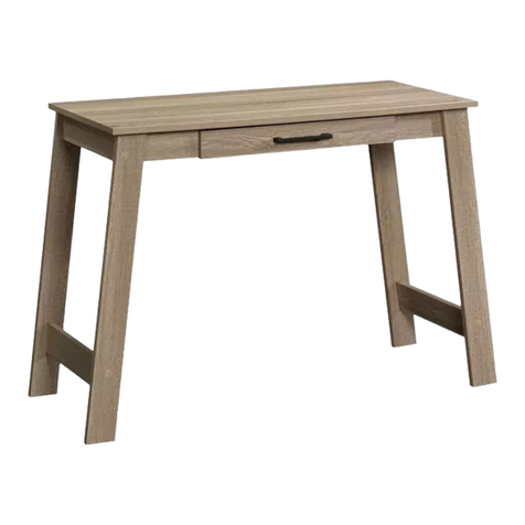
Teknik Scribed Oak Desk 5414836 User manual

Teknik

Teknik Scribed Oak Desk 5414836 User manual

Teknik Avon 5422051 User manual

Teknik

Teknik Avon 5422051 User manual

Teknik 5426436 User manual

Teknik

Teknik 5426436 User manual

Teknik Elstree Credenza 5426916 User manual

Teknik

Teknik Elstree Credenza 5426916 User manual

Teknik 5422379 User manual

Teknik

Teknik 5422379 User manual

Teknik Barrister Home Credenza 5421458 User manual

Teknik

Teknik Barrister Home Credenza 5421458 User manual

Teknik 5422378 User manual

Teknik

Teknik 5422378 User manual

Teknik Barrister Home 4 Drawer Chest User manual

Teknik

Teknik Barrister Home 4 Drawer Chest User manual

Teknik 5420649 User manual

Teknik

Teknik 5420649 User manual

Teknik Hudson Elm finish 5427457 User manual

Teknik

Teknik Hudson Elm finish 5427457 User manual

Teknik Home Study 5426616 User manual

Teknik

Teknik Home Study 5426616 User manual

Teknik Barrister Home L-Shaped Desk 5418270 User manual

Teknik

Teknik Barrister Home L-Shaped Desk 5418270 User manual

Teknik Hampstead Park  Narrow Bookcase 5420283 User manual

Teknik

Teknik Hampstead Park Narrow Bookcase 5420283 User manual

Teknik 5426484 User manual

Teknik

Teknik 5426484 User manual

Teknik 5414142 User manual

Teknik

Teknik 5414142 User manual

Teknik Hudson 5425709 User manual

Teknik

Teknik Hudson 5425709 User manual

Teknik Hudson 5425825 User manual

Teknik

Teknik Hudson 5425825 User manual

Teknik Stationmaster 5426454 User manual

Teknik

Teknik Stationmaster 5426454 User manual

Teknik 5431916 User manual

Teknik

Teknik 5431916 User manual

Teknik Elstree 5426910 User manual

Teknik

Teknik Elstree 5426910 User manual

Teknik Boulevard Cafe 5427345 User manual

Teknik

Teknik Boulevard Cafe 5427345 User manual

Teknik Canal Heights Coffee Table 5419233 User manual

Teknik

Teknik Canal Heights Coffee Table 5419233 User manual

Teknik 5427873 User manual

Teknik

Teknik 5427873 User manual

Teknik New Hyde 426440 User manual

Teknik

Teknik New Hyde 426440 User manual

Popular Indoor Furnishing manuals by other brands

Home Styles 88 5804 22 Assembly instructions

Home Styles

Home Styles 88 5804 22 Assembly instructions

guide craft See and Store Dress Up Center Pastel G98103 Assembly instructions

guide craft

guide craft See and Store Dress Up Center Pastel G98103 Assembly instructions

agatameble MDXV71R Assembling Instruction

agatameble

agatameble MDXV71R Assembling Instruction

HOMEDEPOT NAVONA FTS70575 Use and care guide

HOMEDEPOT

HOMEDEPOT NAVONA FTS70575 Use and care guide

Simpli Home brooklyn+max WyndenHall AXCDRP-07BL quick start guide

Simpli Home

Simpli Home brooklyn+max WyndenHall AXCDRP-07BL quick start guide

HAMPTON BAY FWS00590D Use and care guide

HAMPTON BAY

HAMPTON BAY FWS00590D Use and care guide

Storkcraft 03663-10 AC Series quick start guide

Storkcraft

Storkcraft 03663-10 AC Series quick start guide

Forms + Surfaces COLUMN TABLE installation instructions

Forms + Surfaces

Forms + Surfaces COLUMN TABLE installation instructions

West Elm Portside Dining Armchair manual

West Elm

West Elm Portside Dining Armchair manual

Delta 7886 Assembly instructions

Delta

Delta 7886 Assembly instructions

Aqua One Oakstyle 145 Assembly instructions

Aqua One

Aqua One Oakstyle 145 Assembly instructions

GT Racing GT890MF Assembly instructions

GT Racing

GT Racing GT890MF Assembly instructions

Simpli Home Avington AXCBSAVN07-WH manual

Simpli Home

Simpli Home Avington AXCBSAVN07-WH manual

Home Styles Kitchen Island 88 5047 941 Assembly instructions

Home Styles

Home Styles Kitchen Island 88 5047 941 Assembly instructions

HAMPTON BAY Angelina instruction manual

HAMPTON BAY

HAMPTON BAY Angelina instruction manual

Home Styles 20 05617 0103 quick start guide

Home Styles

Home Styles 20 05617 0103 quick start guide

Simpli Home brooklyn+max WyndenHall AXCHLL-10-HIC quick start guide

Simpli Home

Simpli Home brooklyn+max WyndenHall AXCHLL-10-HIC quick start guide

mlmeble FINI 03 Assembling Instruction

mlmeble

mlmeble FINI 03 Assembling Instruction

manuals.online logo
manuals.online logoBrands
  • About & Mission
  • Contact us
  • Privacy Policy
  • Terms and Conditions

Copyright 2025 Manuals.Online. All Rights Reserved.