manuals.online logo
Brands
  1. Home
  2. •
  3. Brands
  4. •
  5. Wren Kitchens
  6. •
  7. Indoor Furnishing
  8. •
  9. Wren Kitchens Vogue TOWER UNIT 2070 User manual

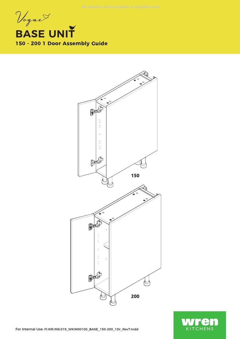
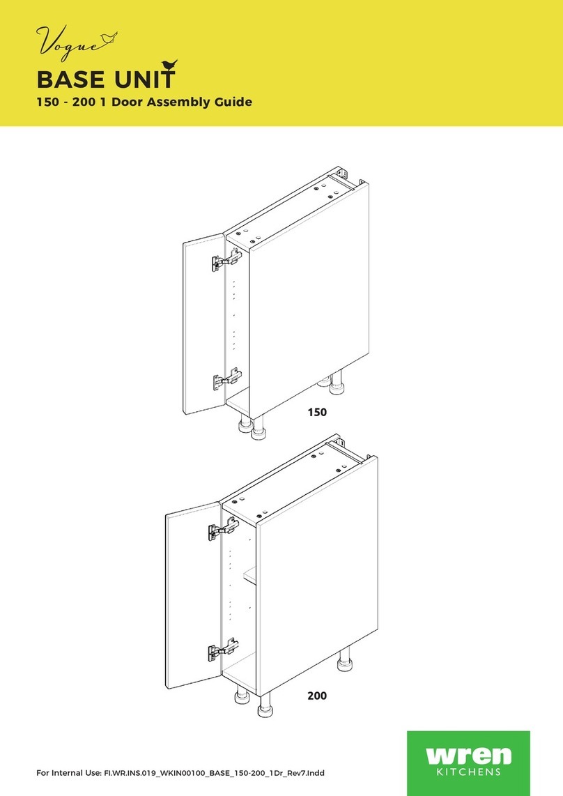
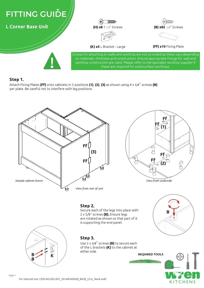
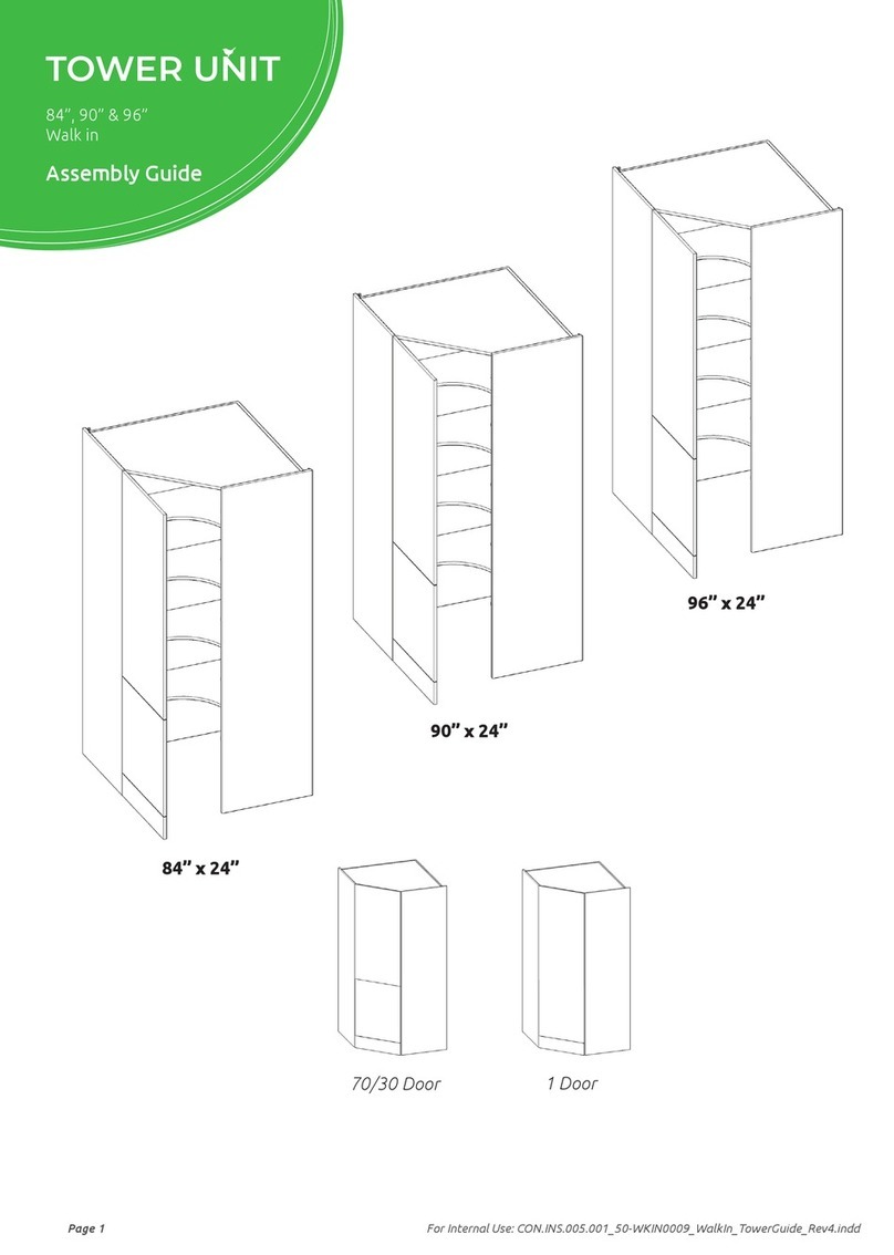
Wren Kitchens Vogue TOWER UNIT 2070 User manual

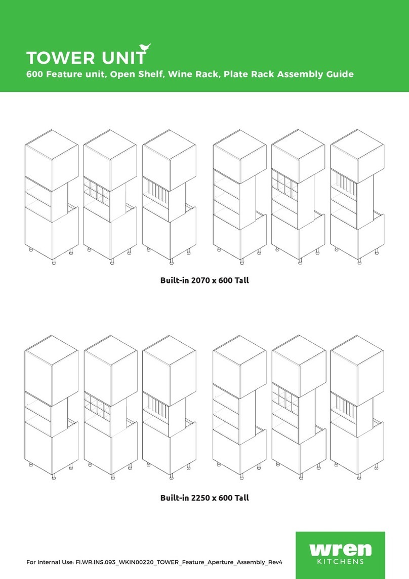
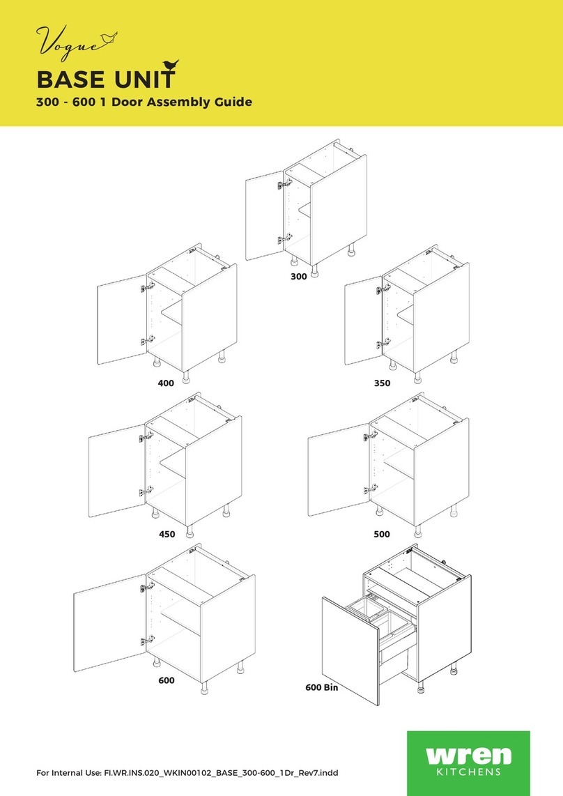
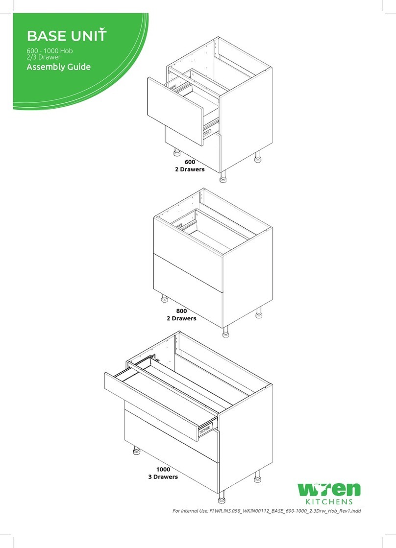
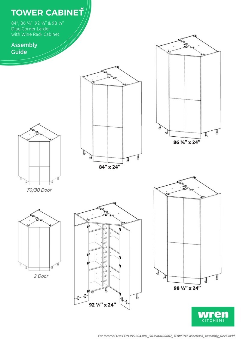
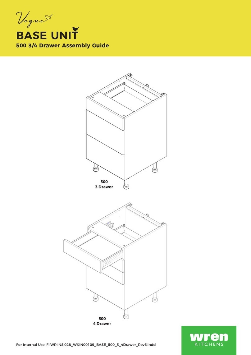
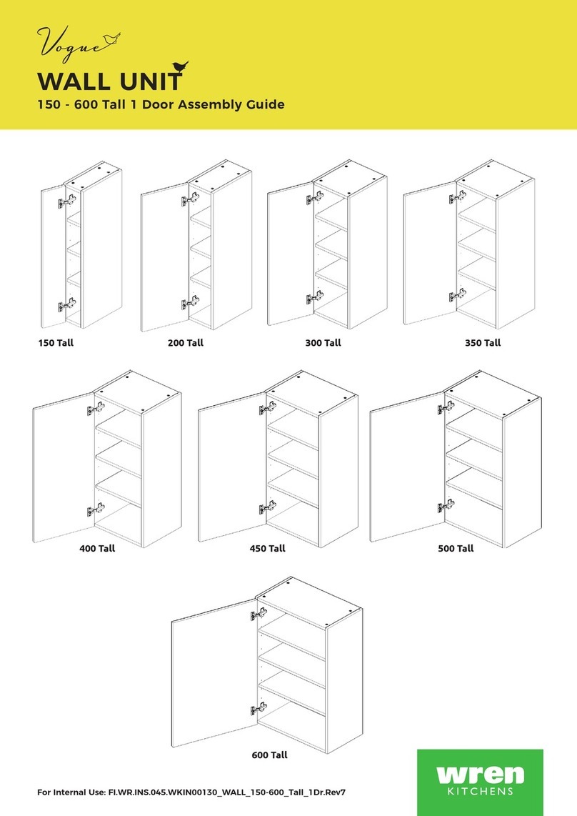
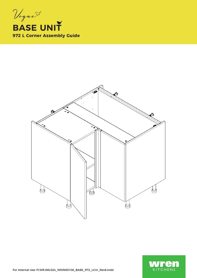
TOWER UNIT
600 Appliance Door & Drawer Assembly Guide
For Internal Use: FI.WR.INS.042_WK00142_TOWER_600_DrDrwAppRange.Rev8
900/600+290 Appliance
2 Door
600/450+140 Appliance
2 Door
600/450+140 Appliance
1 Door +2 Drawer
450 Appliance
1 Door +3 Drawer
A B
C D
2070
2070
2250 Tall
2250 Tall
2070
2070
2250 Tall
2250 Tall
Page 1
TOWER UNIT
600 Appliance Door & Drawer Assembly Guide
Standard Drawer (Packed Separately)
Fitting Pack Contents
REQUIRED TOOLS
NOT to be used
with CAM DOWEL
& CAM LOCK
DRAWER
COVER CAP
x2
DRAWER
COVER CAP
x2
DRAWER SIDE
x1 Right Hand
DRAWER SIDE
x1 Right Hand
DRAWER SIDE
x1 Left Hand
DRAWER SIDE
x1 Left Hand
DRAWER
FRONT
FIXING
x 2
DRAWER
FRONT
FIXING
x 2
Deep Drawer (Packed Separately)
Fitting Pack Contents
(Y) x2
Gallery
Head
(J) x16
Drawer Runner
16mm Screws
(J) x16
Drawer Runner
16mm Screws
(N) x1
Door Buer
(N) x1
Door Buer
(Q) x4
21mm
Screw
(Q) x4
21mm
Screw
(L) x2
15mm
Screw
METAL BACK
PANEL
x 1
METAL BACK
PANEL
x 1
DRAWER
BASE
x 1
DRAWER
BASE
x 1
DRAWER
RUNNER
x 1 Right Hand
DRAWER
RUNNER
x 1 Right Hand
FRONTAL
(Supplied separately)
FRONTAL
(Supplied separately)
DRAWER
RUNNER
x 1 Left Hand
DRAWER
RUNNER
x 1 Left Hand
GALLERY
RAIL
x 2
BEFORE YOU START
INSTALLATION
SHOULD BE
PERFORMED BY A
COMPETENT
PERSON ONLY.
THIS PRODUCT COULD
BE DANGEROUS
IF INCORRECTLY
INSTALLED
Page 2
For Internal Use: FI.WR.INS.042_WK00142_TOWER_600_DrDrwAppRange.Rev8
Step 2.
Clip on metal back panel to drawer base &
drawer sides.
Step 3.
Screw back panel in position using 2 x 16mm screws (J)
to drawer base in holes provided.
Step 1.
Secure drawer base to drawer side using 4 x 16mm
drawer runner screws (J) in holes provided.
Seat the edge of drawer base tight
into corner of casing, as shown.
The decorative face of drawer base
to be positioned as shown.
Metal back
panel
View from back
Metal
back
panel
Drawer base
white
decorative
face up
J
J
J
J
J
J
J
J
J
Front of drawer
Decorative
face
Drawer
base
J
Step 4.
Frontal Attachment
Secure drawer side xing clips using 2 x 21mm
screws (Q) in pilot holes provided as shown.
Drawer
base
Fixing
clip
& (Q)
Fixing
clip
& (Q)
Standard
drawer
Step 6.
Fit Drawer Cover Caps
over drawer side adjustment.
Drawer
Cover Cap
Drawer
frontal
Drawer side
J
Fixing
clip
Drawer side
xing clip
Q
Q
Drawer
frontal
Repeat step 1 so both drawer
sides are attached to drawer base.
View of drawer side
1
3
2b
2a
Step 5.
Draw Adjustment
Screw point 1as shown
to adjust drawer
frontal right & left.
Screw point 2a as
shown to adjust
drawer frontal
up & down.
Tighten 2b
once in position.
Releasing xing clip. Screw
point 3whilst applying
downward pressure as
shown to release.
Page 3
TOWER UNIT
600 Appliance Door & Drawer Assembly Guide
Fixing
clip
& (Q)
Fixing
clip
& (Q)
2
1
Y & L Y & L
Step 6.
Fit gallery rail into the top
corners of metal back panel.
Locate front end of the
gallery rail into the opening
of the gallery head, which
is secured to the frontal as
shown
Deep
drawer
J
J
Metal
back
panel
Drawer base
white decorative
face up
Step 4.
Frontal Attachment
Secure drawer side xing clips using 2 x 21mm screws (Q)
& Gallery Head (Y) using 1 x 15mm screws (L) in pilot holes
provided as shown.
Fixing clip
(Y) Gallery
Head
Drawer side
xing clip
Q
Q
Drawer
frontal
Drawer
side
Drawer
frontal
Step 7.
Fit drawer cover caps
over drawer side adjustment.
Drawer
Cover Cap
Step 2.
Clip on metal back panel to drawer base &
drawer sides.
Step 3.
Screw back panel in position using 2 x 16mm screws (J)
to drawer base in holes provided.
Step 1.
Secure drawer base to drawer side using 4 x 16mm
drawer runner screws (J) in holes provided.
Seat the edge of drawer base tight
into corner of casing, as shown.
The decorative face of drawer base
to be positioned as shown.
View from back
Metal
back
panel
Front of drawer
Decorative
face
Drawer
base
J
J
JJ
JJ
Drawer
base
J
Repeat step 1 so both drawer
sides are attached to drawer base.
JJ
Step 5.
Draw Adjustment
Screw point 1as shown to
adjust drawer frontal
right & left.
Drawer Frontal
Adjustment
Screw point 2a
as shown to adjust
drawer frontal up & down.
Tighten 2b
once in position.
Releasing
xing clip.
Screw point 3
whilst applying
downward pressure
as shown to release. View of drawer side
13
2b
2a
Page 4
For Internal Use: FI.WR.INS.042_WK00142_TOWER_600_DrDrwAppRange.Rev8
REQUIRED TOOLS
NOT to be used
with CAM DOWEL
& CAM LOCK
(F) x16
Wooden
Dowel
(L) x24
15mm
Screw
(G) x16
Cam Dowel
(Expanding)
(H) x12
Cam lock
(M) x4
Cover Cap
(K) x16
30mm
Screw
(R) x30
19mm
Screw
(N) x2
Door Buer
(Z) x12
Shelf Peg
Plastic
L Bracket LGE
x2
Hinge Mounting Plate
x2 or 4
Inc Screws
Hinge x2 or 4
Where applicable
(Inc Screws)
(U) x2
Fixing Plate
Panel B
x2 End Panel
Panel A
x2 Back Panel
Panel E
x2 Rail
Loose Shelf
(where applicable)
x1or 2
Legs
x5
Frontals
(Packed separately)
Fixed Shelf C
x2 Base Panel
BEFORE YOU START
INSTALLATION
SHOULD BE
PERFORMED BY A
COMPETENT
PERSON ONLY.
THIS PRODUCT COULD
BE DANGEROUS
IF INCORRECTLY
INSTALLED
Page 5
TOWER UNIT
600 Appliance Door & Drawer Assembly Guide
600/450+140 Appliance
1 Door+2 Drawer
2070 & 2250 Tall
450 Appliance
1Door+3Drawer
2070 & 2250 Tall
C
D
Step 1.
To attach drawer runner screw into end panels (B)
using 2 x 16mm screws (J) per drawer rail, into pilot holes provided,
3rd hole from front, as shown.
Drawer runner bracket screw position
J J
J
J
Fixed Shelf
282mm Fixed Shelf
282mm
Fixed Shelf
1468mm
BTM BTM
74mm 74mm
37mm
37mm
261mm
261mm
From Bottom From Bottom
From
Front
From
Front
B
LEFT HAND RIGHT HAND
B
TOP TOP
D
789mm
C&D
431mm
Page 6
For Internal Use: FI.WR.INS.042_WK00142_TOWER_600_DrDrwAppRange.Rev8
FOR PANEL(C) POSITIONS
SEE SHEET 7
Step 1.
Seat dowel (F) into holes in
both end panels (B) as shown.
Step 2.
Seat cam dowel (G) into holes in
both end panels (B) as shown.
Step 4.
Insert cam lock (H).
Do NOT tighten until Step 7.
NB. All cam locks (H) are to be positioned facing the
outside of the unit carcase, for ease of tightening.
Do not use power tools with
cam dowel (G) or cam lock (H)
B
C
View from underside
H
H
B
B
EE
C
C
CC
Step 3.
Attach Panels (C) & (E) to panels (B), using
cam dowel (G) (in blue) and also using dowels
(F) (in orange) in positions as shown on.
SEE SHEET 7 or 8 WHERE APPLICABLE.
B
C
View from underside
G
G
Seat (G)
cam dowel
into hole as
shown.
Page 7
TOWER UNIT
600 Appliance Door & Drawer Assembly Guide
From Bottom
From Bottom
126mm
94mm
126mm
94mm
481mm
449mm
481mm
449mm
626mm
594mm
626mm
594mm
1445mm
1413mm
1445mm
1413mm
1592mm
1560mm
1592mm
1560mm
1826mm
1794mm
1826mm
1794mm A B C D
A B C D
A B C D
A B C D
A B C D
A B C D
A B
A B
A
A
A
A
B C D
B C D
B C D
B C D
DD
B
B
A
A
A
A
B C
B C
1468mm
1468mm
1322mm
1322mm
854mm854mm
711mm
711mm
568mm
568mm
BTM
BTM
TOP
TOP
HINGE & FIXED SHELF (B)
POSITIONS
600/450+140 Appliance
1 Door+2 Drawer
2070
900/600+290 Appliance
2 Door
2070
450 Appliance
1Door+3 Drawer
2070
600/450+140 Appliance
2 Door
2070
CA
BB
LEFT HAND RIGHT HAND
DB
Page 8
For Internal Use: FI.WR.INS.042_WK00142_TOWER_600_DrDrwAppRange.Rev8
HINGE & FIXED SHELF (B)
POSITIONS
600/450+140 Appliance
1 Door+2 Drawer
2250 Tall
900/600+290 Appliance
2 Door
2250 Tall
450 Appliance
1Door+3 Drawer
2250 Tall
600/450+140 Appliance
2 Door
2250 Tall
CA DB
From BottomFrom Bottom
126mm
94mm
126mm
94mm
481mm
449mm
481mm
449mm
626mm
594mm
626mm
594mm
1445mm
1413mm
1445mm
1413mm
1595mm
1563mm
1595mm
1563mm
2006mm
1974mm
2006mm
1974mm A B C D
A B C D
A B C D
A B C D
A B
A B
A
A
A
A
B C D
B C D
B C D
B C D
D
D
B
B
A
A
A
A
B C
B C
1468mm
1468mm
1322mm
1322mm
854mm
854mm
711mm
711mm
568mm
568mm
BTM
BTM
B B
LEFT HAND RIGHT HAND
A B C DA B C D TOPTOP
Page 9
TOWER UNIT
600 Appliance Door & Drawer Assembly Guide
9mm
9mm
K
A
C
K
Step 5.
Cut back panel (A) to suit appliance
option, to leaving the centre appliance
aperture open.
B
A A
A
A
C
C
E
E
Step 6.
Slide back panel (A) into groove of
end panels (B).
Once back panel (A) is in position,
ensure the panel is ush & square with
bottom of end panels (B).
Step 8.
Ensure unit is square.
Secure back panel (A)
with 12 x 30mm screws
(K) equally spaced at the
top & bottom of back
panels (A) into base
panels (C),
as shown.
Ensure you screw into
the centre of base panel
(C) (9mm from the top
or bottom edge where
applicable).
Step 7.
Hand tighten all cam locks (H), this will
expand cam dowels (G) and tighten
the unit together.
Page 10
For Internal Use: FI.WR.INS.042_WK00142_TOWER_600_DrDrwAppRange.Rev8
B
B
Front
Front
C
Leg position diagram
Step 9.
Position legs as shown.
Ensure legs are rotated to also provide
support to the end panels (B).
Step 10.
Secure each of the legs into place with
4 x 15mm screws (L) per leg.
B
L
L
L
L
C
B
C
Step 11.
Push leg rmly down into leg base.
Adjust legs to 155mm before turning unit upright.
Once in situ level accordingly.
It is important to lift unit
onto its legs. Do not tilt as
depicted in image.
Page 11
TOWER UNIT
600 Appliance Door & Drawer Assembly Guide
Secure tower to the wall using L brackets.
Use 2 x 15mm screws (L) to secure each of the L brackets to
the units at either side.
Then screw through into the wall as shown.
Secure tower to the wall using screws through rail panel (E)
into the wall as shown.
Screw into any side units using the 30mm screws (K)
provided to secure to unit.
Screw just to the rear of the hinge mounting plate, at the
top and bottom of both sides of the unit, place a cover cap
on the head to conceal it.
L
L
E
E
K
Screws for attaching to walls are not provided as these vary depending on
materials, thickness and construction. Ensure appropriate xings for wall
construction are used.
Page 12
For Internal Use: FI.WR.INS.042_WK00142_TOWER_600_DrDrwAppRange.Rev8
See Customer Specic Kitchen Plan For Tower Frontals
Step 12.
Insert hinge in top & bottom
holes as shown below.
Step 13.
Secure hinges by tightening
2 x screws with hinge dowels
attached. These are already
positioned within the hinges.
Step 14.
Attach the door to unit
where required.
To attach door, clip hinge
onto hinge plate and click
to secure.
Hinge Cover Caps
Step 16.
Fit cover caps to hinge.
Adjust Soft close to suit.
Step 15.
Adjust hinge to suit. As shown below.
To adjust hinge using
a screw driver, tighten
or loosen as required
at points 1& 2.
Point 1- In - Out
Point 2- Left - Right
12
FRONTAL
HINGE
ADJUSTMENT
Hinge Plates
View from inside of Unit
To release door,
pull catch as shown,
to release hinge from
the hinge plate.
The top and bottom
hinges MUST be
adjusted to the SAME
STRENGTH.
To Move the
hinge up/down,
loosen screws
A + B,
Manoeuvre
the door, then
re-tighten the
screws
A
B
Page 13
TOWER UNIT
600 Appliance Door & Drawer Assembly Guide
Page 14
For Internal Use: FI.WR.INS.042_WK00142_TOWER_600_DrDrwAppRange.Rev8

This manual suits for next models

5

Other Wren Kitchens Indoor Furnishing manuals
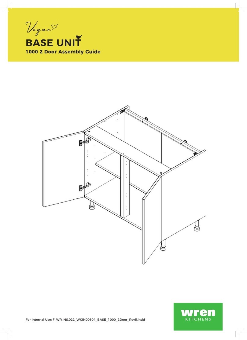
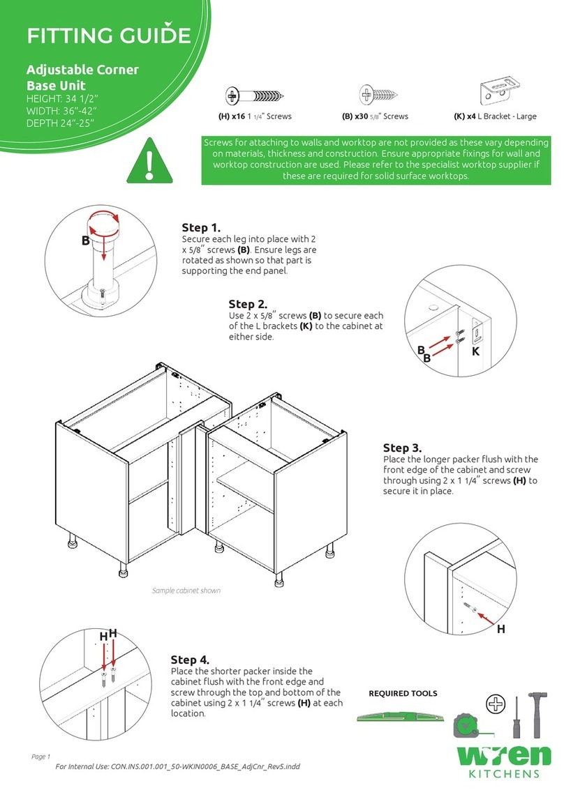
Wren Kitchens Adjustable Corner Base Unit Assembly instructions

Wren Kitchens

Wren Kitchens Adjustable Corner Base Unit Assembly instructions

Wren Kitchens BASE UNIT 600 User manual

Wren Kitchens

Wren Kitchens BASE UNIT 600 User manual

Wren Kitchens Vogue BASE UNIT 500 3 Drawer User manual

Wren Kitchens

Wren Kitchens Vogue BASE UNIT 500 3 Drawer User manual

Wren Kitchens TOWER UNIT 84 Walk in User manual

Wren Kitchens

Wren Kitchens TOWER UNIT 84 Walk in User manual

Wren Kitchens 2070 User manual

Wren Kitchens

Wren Kitchens 2070 User manual

Wren Kitchens BASE UNIT 600 User manual

Wren Kitchens

Wren Kitchens BASE UNIT 600 User manual

Wren Kitchens Vogue BASE UNIT 150 Pull Out User manual

Wren Kitchens

Wren Kitchens Vogue BASE UNIT 150 Pull Out User manual

Wren Kitchens MIDWAY CABINET User manual

Wren Kitchens

Wren Kitchens MIDWAY CABINET User manual

Wren Kitchens Vogue BASE UNIT 1000 2 Door User manual

Wren Kitchens

Wren Kitchens Vogue BASE UNIT 1000 2 Door User manual

Wren Kitchens Vogue BASE UNIT 600 2 Drawers Dummy User manual

Wren Kitchens

Wren Kitchens Vogue BASE UNIT 600 2 Drawers Dummy User manual

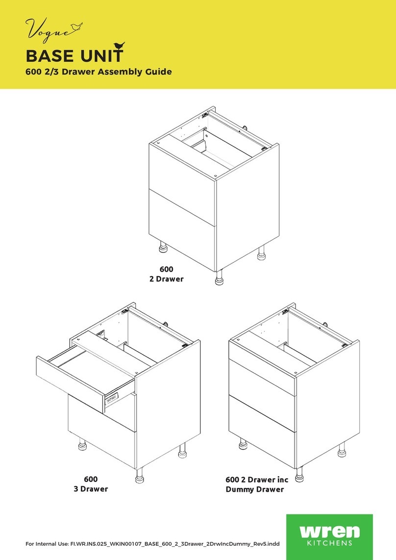
Wren Kitchens BASE UNIT 600 User manual
Wren Kitchens

Wren Kitchens BASE UNIT 600 User manual

Wren Kitchens Vogue BASE UNIT 600 2 Drawer User manual
Wren Kitchens

Wren Kitchens Vogue BASE UNIT 600 2 Drawer User manual

Wren Kitchens TOWER UNIT User manual

Wren Kitchens

Wren Kitchens TOWER UNIT User manual

Wren Kitchens L Corner Base Unit Assembly instructions

Wren Kitchens

Wren Kitchens L Corner Base Unit Assembly instructions

Wren Kitchens BASE 3 Assembly instructions

Wren Kitchens

Wren Kitchens BASE 3 Assembly instructions

Wren Kitchens BASE UNIT 600 User manual

Wren Kitchens

Wren Kitchens BASE UNIT 600 User manual

Wren Kitchens Vogue BASE UNIT 800 2 Door User manual

Wren Kitchens

Wren Kitchens Vogue BASE UNIT 800 2 Door User manual

Wren Kitchens BASE UNIT 1000 User manual

Wren Kitchens

Wren Kitchens BASE UNIT 1000 User manual

Wren Kitchens WALL UNIT 672 L Corner User manual

Wren Kitchens

Wren Kitchens WALL UNIT 672 L Corner User manual

Wren Kitchens Vogne 150 User manual

Wren Kitchens

Wren Kitchens Vogne 150 User manual
Wren Kitchens FI.PK.FIT.004 User manual

Wren Kitchens

Wren Kitchens FI.PK.FIT.004 User manual

Wren Kitchens BASE UNIT 600 User manual

Wren Kitchens

Wren Kitchens BASE UNIT 600 User manual

Wren Kitchens Vogue TOWER UNIT Boiler Housing User manual

Wren Kitchens

Wren Kitchens Vogue TOWER UNIT Boiler Housing User manual

Wren Kitchens BASE 3 MILANO Assembly instructions

Wren Kitchens

Wren Kitchens BASE 3 MILANO Assembly instructions

Popular Indoor Furnishing manuals by other brands

Himolla Cumuly Comfort 29111 43 Assembly instructions

Himolla

Himolla Cumuly Comfort 29111 43 Assembly instructions

HULALA HOME SFYB0365 quick start guide

HULALA HOME

HULALA HOME SFYB0365 quick start guide

ofinto Active 3D user manual

ofinto

ofinto Active 3D user manual

EDN reale manual

EDN

EDN reale manual

Pinolino 13 00 13 R Assembly plan

Pinolino

Pinolino 13 00 13 R Assembly plan

Habitat Venetie manual

Habitat

Habitat Venetie manual

Hinkle Chair Company 700 SLAT ROCKER Assembly instructions

Hinkle Chair Company

Hinkle Chair Company 700 SLAT ROCKER Assembly instructions

BLACK RED WHITE STYLIUS NBIU 170 Assembly manual

BLACK RED WHITE

BLACK RED WHITE STYLIUS NBIU 170 Assembly manual

Julian Bowen CHE201 Assembly instructions

Julian Bowen

Julian Bowen CHE201 Assembly instructions

hawa HAWA-Frontslide 60/matic-Telescopic 4 Planning and installation instructions

hawa

hawa HAWA-Frontslide 60/matic-Telescopic 4 Planning and installation instructions

LHFD C2010001 Assembly instructions

LHFD

LHFD C2010001 Assembly instructions

MANCHESTER WOOD Cherry Contemporary Media Stand Assembly instructions

MANCHESTER WOOD

MANCHESTER WOOD Cherry Contemporary Media Stand Assembly instructions

RH Teen KIERAN manual

RH Teen

RH Teen KIERAN manual

Furinno 17081 Assembly instruction

Furinno

Furinno 17081 Assembly instruction

Prosedia Younico PRO Assembly and operating instructions

Prosedia

Prosedia Younico PRO Assembly and operating instructions

RTA TVM-060 Assembly instructions

RTA

RTA TVM-060 Assembly instructions

Biohort Shelves Assembly manual

Biohort

Biohort Shelves Assembly manual

ROOMS TO GO SYNE K2111-73PHR-Air Assembly instructions

ROOMS TO GO

ROOMS TO GO SYNE K2111-73PHR-Air Assembly instructions

manuals.online logo
manuals.online logoBrands
  • About & Mission
  • Contact us
  • Privacy Policy
  • Terms and Conditions

Copyright 2025 Manuals.Online. All Rights Reserved.