3
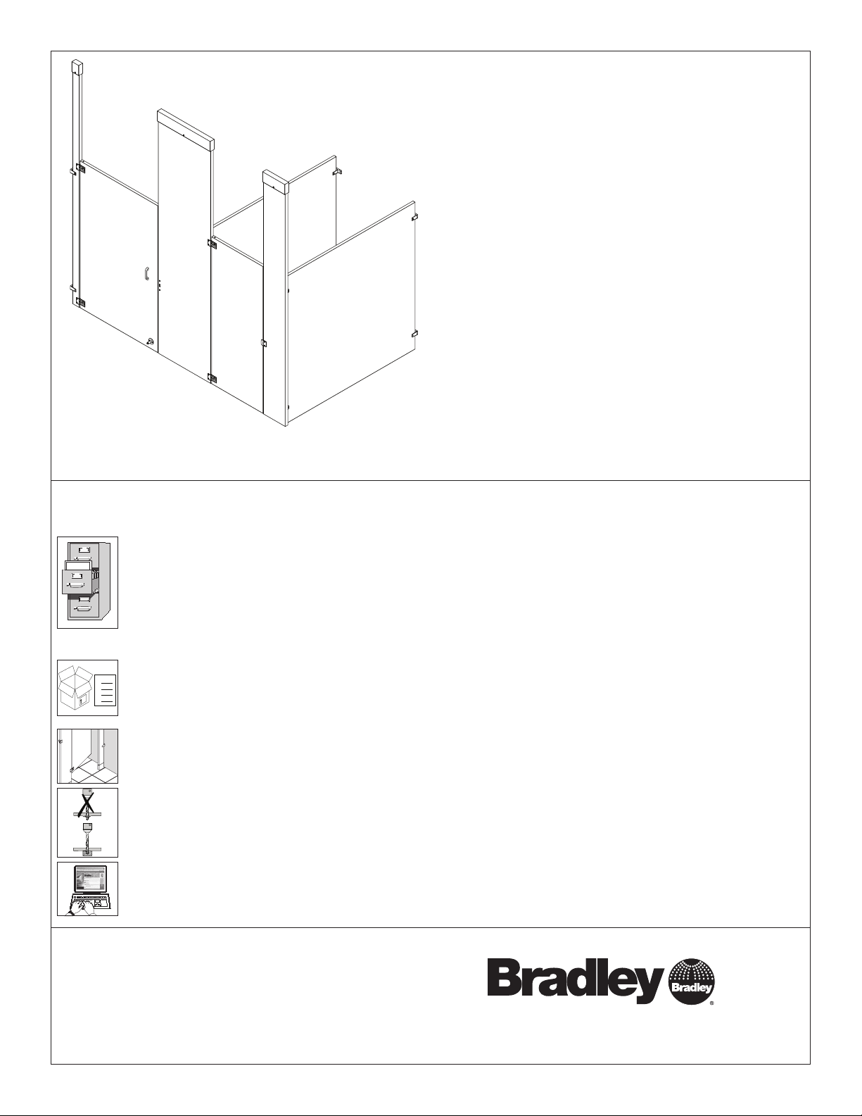
Installation Plastic Laminate Restroom Partitions, Ceiling-Hung — Series 600
Bradley • HDWL-INSTR-003 Rev. D; ECN 13-14-030B 8/29/2013
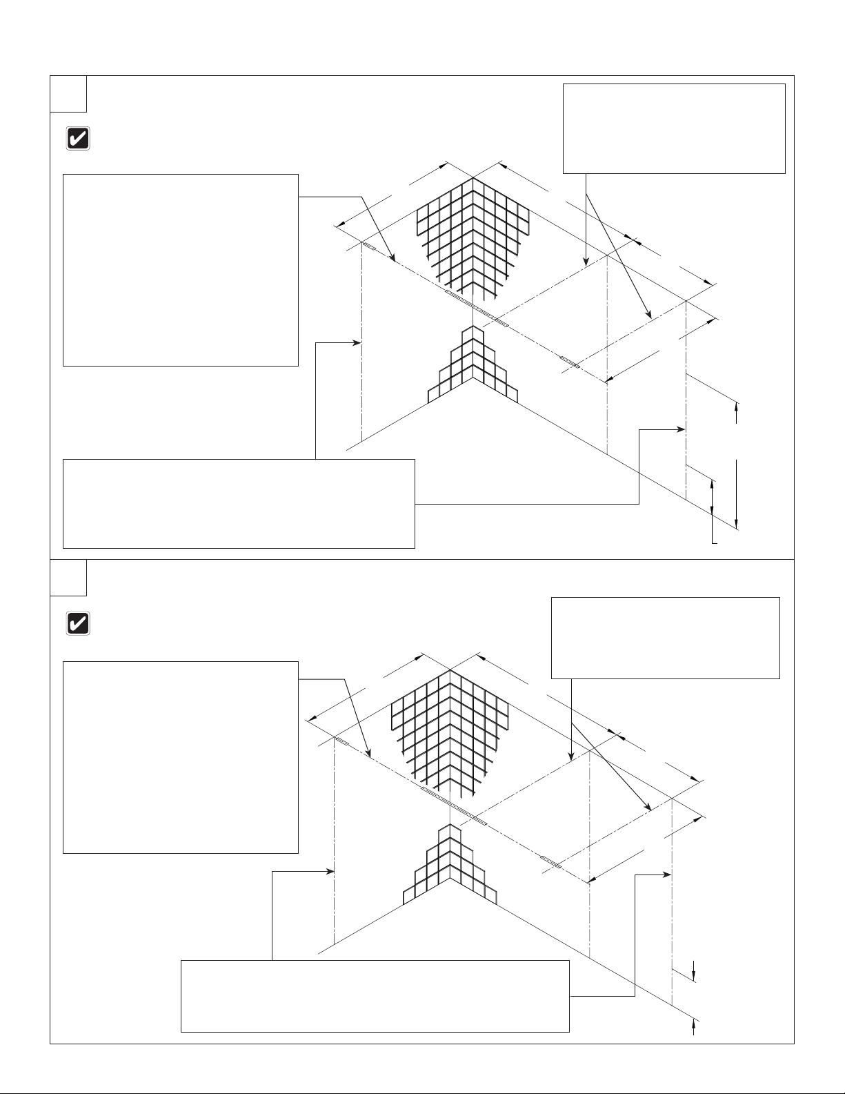
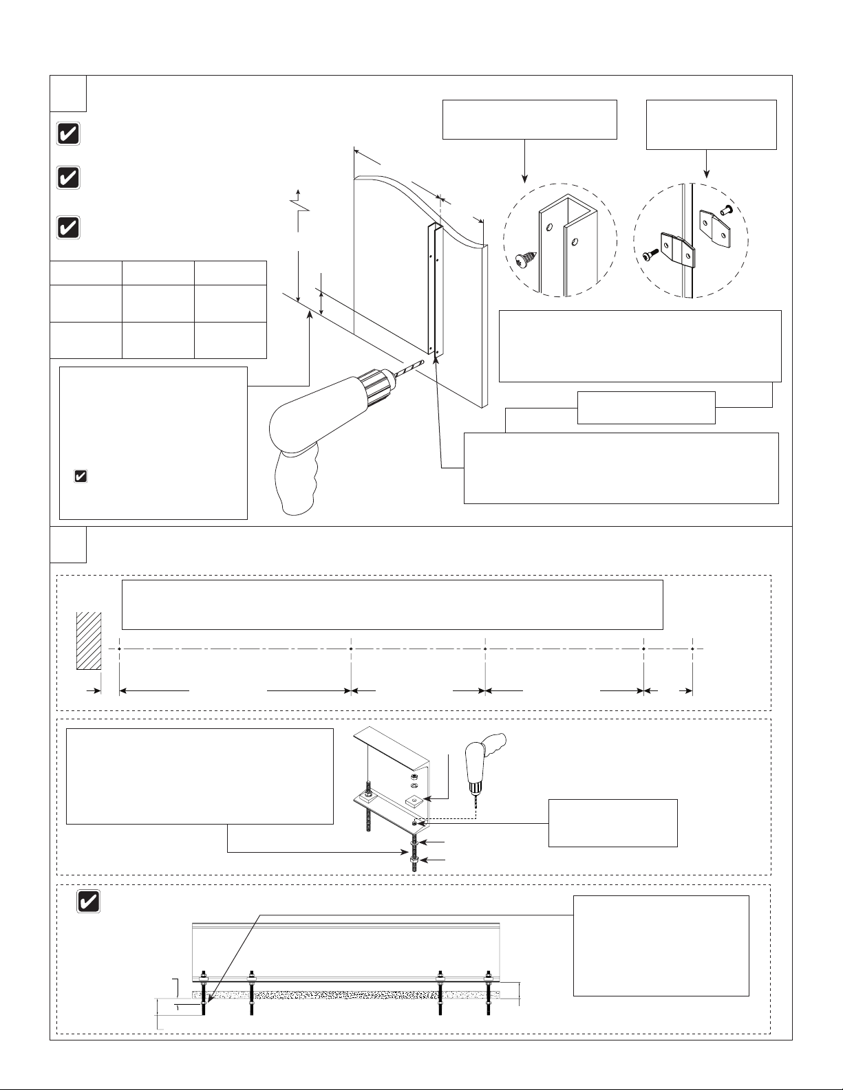
1Layout Dimensions - Stirrup Bracket (Standard)
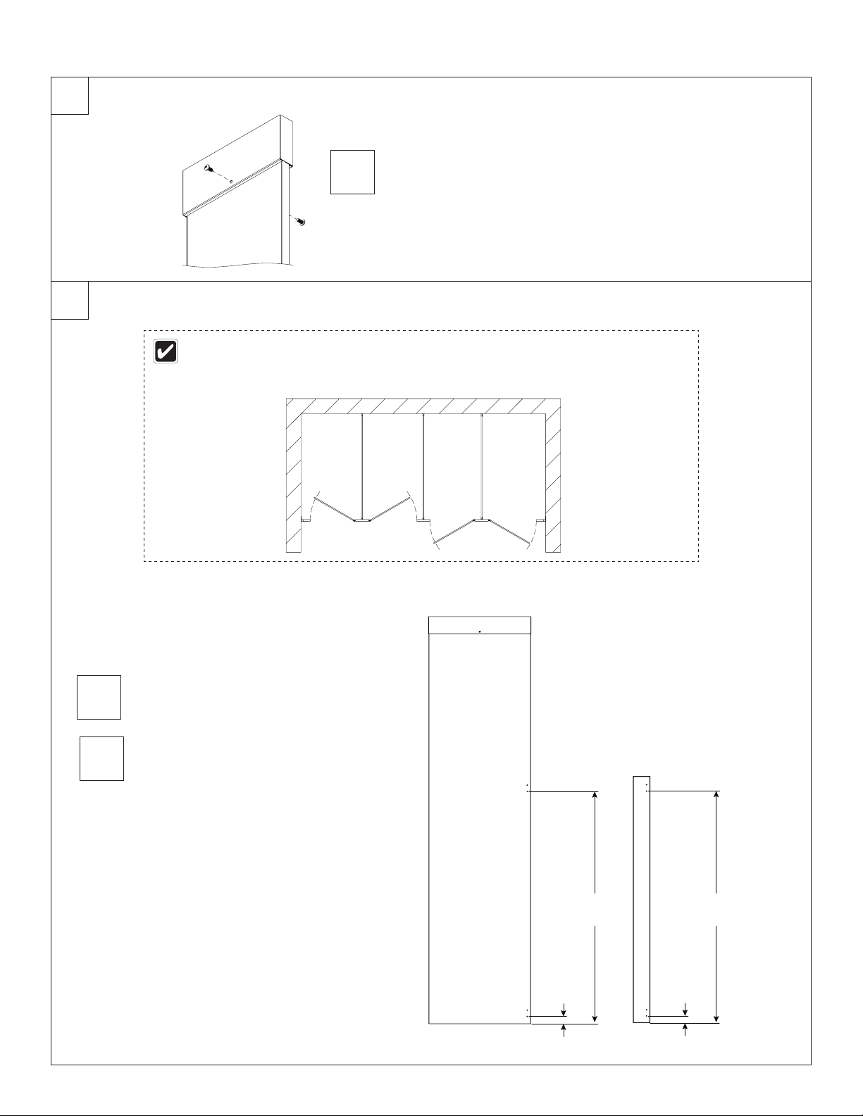
When installing the partition components, consult
the applicable Mills Partition submittal drawing
for compartment layout dimensions.
When installing the partition components, consult
the applicable Mills Partition submittal drawing
for compartment layout dimensions.
Pilaster centerline: Measure from
the back wall forward to the face of the
compartment, subtract ⁵⁄₈" (16mm) and
mark this location on the ceiling (“A”).
Mark the same measurement on the
opposite end of your layout (“A1”) and
draw a straight line connecting both
marks.
FOR FREESTANDING (FS)
PARTITIONS: Refer to submittal
drawings and determine the
approximate location of the outside
panels. Establish dimensions “A” and
“A1” as explained above.
A
Panel centerline: Measure the stall
width across the back wall and
place a mark at the top of the rear
wall (“B”). Repeat this step for each
panel, starting each measurement
from the last panel centerline (“B1”).
B
Stirrup brackets: Draw a plumb line on all walls from each
pilaster and panel centerline. From the highest point in the
room, measure 18" (457mm) and 64" (1626mm) from the floor
and place a mark on the pilaster/panel plumb line. These marks
represent the hole center line of the stirrup brackets. Use a
level to transfer that mark to all other plumb lines (“C”).
C
*
"C"
*
"C"
C
LC
L
C
L
C
L
"A"
"B"
"A1"
"B1"
*
"C"
*
"C"
C
L
*
"C"
C
L
*
"C"
*
"C"
C
LC
L
C
L
C
L
"A"
"B"
"A1"
"B1"
*
"C"
Panel
plumb line
Pilaster
plumb line
64"
(1626mm)
18" (457mm)
Pilaster centerline: Measure from
the back wall forward to the face of the
compartment, subtract ⁵⁄₈" (16mm) and
mark this location on the ceiling (“A”).
Mark the same measurement on the
opposite end of your layout (“A1”) and
draw a straight line connecting both
marks.
FOR FREESTANDING (FS)
PARTITIONS: Refer to submittal
drawings and determine the
approximate location of the outside
panels. Establish dimensions “A” and
“A1” as explained above.
A
Panel centerline: Measure the stall
width across the back wall and place
a mark at the top of the rear wall
(“B”). Repeat this step for each panel,
starting each measurement from the
last panel centerline (“B1”).
B
Panel
plumb line
Pilaster plumb line
1a Layout Dimensions - Continuous Bracket (Optional)
Continuous brackets: Draw a plumb line on all walls from each
pilaster and panel centerline. From the highest point in the room,
measure 12½" (318mm) (for stainless steel) or 12¼" (311mm) (for
aluminum) from the floor and place a mark on the pilaster/panel plumb
line. Use a level to transfer that mark to all other plumb lines (“C”).
C