manuals.online logo
Brands
  1. Home
  2. •
  3. Brands
  4. •
  5. Brink
  6. •
  7. Automobile Accessories
  8. •
  9. Brink 4517 User manual

Brink 4517 User manual

Fitting instructions
Make:
Type:
Permanently
linked to
quality
A3 Sportback; 2004->
Audi
4517
© 451770/15-02-2005/1
tested
euro Approved
Approved
Approved
Max. vertical load : kg
Max. mass trailer : kg
e11 00-5421
94/20/EC
Couplingsclass: A50-X
1800
75
D-Value: 9.6 kN
0km +1000km
M10 17 46 Nm
M12 19 71 Nm (self-locking)
© 451770/15-02-2005/10
© 451770/15-02-2005/9
4517/50
9550017
9550017
M10x30 (10.9)
M10x30 (10.9)
M12x90
9531242
9535286
A
A
M12
self-locking
4517/12
© 451770/15-02-2005/2
MONTAGEHANDLEIDING:
1. Demonteer de achterlicht units.
2. Demonteer de bumper.
3. Demonteer de dwarsbalk van het voertuig (herplaats de bouten)
4. Zaag het aangegeven deel uit de bumper met behulp van de sjabloon.
5. Verwijder de tape t.p.v. de bevestigingspunten.
6. Monteer trekhaak in chassis.
7. Draai alle bouten overeenkomstig tabel vast.
8. Plaats de twee PE schuimblokken als afdichting in de chassisbalken.
9. Monteer het kogelhuis.
10.Draai alle bouten en moeren overeenkomstig tabel vast.
11.Monteer de bumper
12.Monteer de achterlicht units.
Raadpleeg voor montage en bevestigingsmiddelen de schets.
Raadpleeg voor demontage en montage van voertuig onderdelen het
werkplaats handboek.
Raadpleeg voor montage en demontage van het afneembare kogel-
systeem de bijgevoegde montagehandleiding.
FITTING INSTRUCTIONS:
1. Remove the rear-light units.
2. Remove the bumper.
3. Remove the cross member from the vehicle (replace the bolts).
4. Use the template to saw out the indicated section from the bumper.
5. Remove the tapeat points of attachment.
6. Fit the tow bar to the chassis.
7. Tighten all bolts to the torque indicated in the table.
8. Place the two PE foam blocks as spacers in the chassis members.
9. Fit the ball housing.
10.Tighten all nuts and bolts to the torque indicated in the table.
11.Fit the bumper.
12.Remove the rear-light units.
For fitting instructions and attachment method, see drawing.
For dismantling and fitting the vehicle parts, see the site handbook.
See the assembly manual supplied for instructions on fitting the
removable ball system.
NL
© 451770/15-02-2005/3
GB
BELANGRIJK:
* Voor eventueel noodzakelijke aanpassing(en) “van het voertuig” dient
men de dealer te raadplegen.
* Indien op de bevestigingspunten een bitumen of anti-dreunlaag aanwe-
zig is, dient deze verwijderd te worden.
* Voor de max. toegestane massa, welke uw auto mag trekken, dient u uw
dealer te raadplegen.
* Bij het boren dient men er zorg voor te dragen, dat electriciteits-, rem- en
brandstofleidingen niet worden geraakt.
* Verwijder "indien aanwezig" de plastik dopjes uit de puntlasmoeren.
* Deze handleiding dient na montage bij de voertuigpapieren gevoegd te
worden.
NOTE:
* Should this installation process entail the cutting of the bumper –
conformation MUST be obtained by the installation engineer of
the customer’s acceptance prior to completion. Brink International
do not accept responsibility for any matters arising as a result of
this miscommunication.
* The dealer should be consulted for possible necessary adjustment(s)
"of the vehicle" .
* Remove the insulating material from the contact area of the fitting
points.
* Consult your dealer for the maximum tolerated pull weight and ball
hitch pressure of your vehicle.
* Do not drill through electrical-, brake- or fuellines.
* Remove (if present) the plastic caps from the spot welding nuts.
© 451770/15-02-2005/8
Dispositivo di traino tipo: Brink 4517
Per autoveicoli: A3 Sportback; 2003->
Tipo funzionale:
Classe e tipo di attacco: A50-X
Omologazione: e11 00-5421
Valore D: 9,6 kN
Carico Verticale max. S: 75 kg
Larghezza rimorchiabile per Caravan e T.A.T.S.: 2,45m vedere CARTA di CIRCOLAZIONE VEICOLO (motrice) + 70 cm = ..arrotondare ai 5 cm
superiore (vedi D.M.28/05/85)
Massa rimorchiabile: vedi carta di circolazione dell’ autoveicolo
Per verificare l’idoneitŕ del dispositivo di traino omologato a norma
CEE 94/20, all’installazione sulla vettura su cui si intende procedere
al montaggio, compilare la seguente formula (se necessario
declassare la massa rimorchiabile): dove: T= Massa Complessiva Max. della motrice (in kg)
C= Massa Rimorchiabile Max. della motrice (in kg)
DA COMPILARE PER IL COLLAUDO
DICHIARAZIONE DI CORRETTO MONTAGGIO: la sottoscritta Ditta dichiara di aver montato in maniera corretta ed in conformitŕ alle pres-
crizioni sia del costruttore del veicolo che del costruttore del dispositivo stesso il seguente dispositivo di attacco meccanico:
tipo:..........................................................................................
Il dispositivo di attacco sopra indicato èstato installato su autoveicolo
modello:...................................................................................
targa:........................................................................................
Data:.........................................................................................
Si dichiara inoltre di aver informato l’utente del veicolo sull’USO e MANUTENZIONE del dispositivo stesso.
TIMBRO e FIRMA
INSTRUKCJA MONTAŻU.:
1. Zdemontować zespół tylnych świateł.
2. Zdemontować zderzak.
3. Zdemontować poprzecznicę z pojazdu (zderzak ponownie śruby).
4. Wypiłować wskazany odcinek zderzaka korzystając z szablonu.
5. Usunąć taśmę w miejscu punktów montażowych.
6. Zamontować hak holowniczy do podwozia.
7. Dokręcić wszystkie śruby zgodnie z tabelą.
8. Umieścić dwa klocki piankowe PE jako szczeliwo w poprzecznicach
ramy podwozia.
9. Zamontować obudowę kuli.
10.Dokręcić wszystkie śruby i nakrętki zgodnie z tabelą.
11.Zamontować zderzak.
12.Zamontować zespoły tylnych świateł.
Co do montażu i środków montażowych zapoznać się ze schematem.
Co do montażu i montowania części pojazdu zapoznać się z podręcz-
nikiem warsztatowym.
Co do montażu i demontażu zdejmowanej kuli zapoznać się z załąc-
zoną instrukcją montażu .
© 451770/15-02-2005/7
Wskazówki:
- Po przejechaniu 1000 km dokręcić wszystkie elementy skręcane.
- Podczas ewentualnych odwiertów upewnić się czy w pobliżu nie znaj-
PL
* Rimuovere lo strato di materiale isolante dai punti d'attacco.
* Per il peso complessivo trainabile della Vostra vettura, consultate il
Vostro rivenditore autorizzato.
* Praticando i fori, prestare attenzione a non danneggiare i cavi elettrici, i
cavi del freno e i condotti del carburante.
* Rimuovere, se presenti, i coperchietti in plastica dai dadi di saldatura per
punto.
* Questa istruzione di montaggio deve essere allegata ai documenti del
veicolo dopo l'installazione del gancio.
dują się przewody instalacji elektrycznej, przewody hydrauliczne lub
przewody paliwowe.
- Wszystkie ubytki powłoki lakierniczej zabezpieczyć przed korozją.
- Należy wyjąć ewentualne plastikowe zaślepki w punktach przyspawa-
nych nakrętek.
- Stosować nakrętki oraz śruby gatunkowe dostarczone w komplecie.
- Utrzymywać kulę w czystości, oraz pamiętać o regularnym jej smarowa-
niu.
- Hak holowniczy zarejestrować w stacji diagnostycznej.
Zastosowanie się do powyższych wskazań gwarantuje Państwu bezpiec-
zeństwo, niezawodność i sprawność naszego wyrobu przez cały okres
jego użytkowania.
MONTAGEANLEITUNG:
1. Die Rücklichter abmontieren.
2. Die Stoßstange abmontieren.
3. Den Querträger vom Fahrzeug abmontieren (die Schrauben wieder
anbringen).
4. Den angegebenen Teil mit Hilfe der Schablone aus der Stoßstange her-
ausschneiden.
5. Das Tape bei den Befestigungspunkten entfernen.
6. Die Anhängervorrichtung im Langsträger befestigen.
7. Alle Schrauben gemäß den Angaben in der Tabelle festdrehen.
8. Die zwei PE-Schaumblöcke als Dichtung in den Fahrgestellträger eins-
etzen.
9. Das Kugelgehäuse montieren.
10.Alle Schrauben und Muttern gemäß den Angaben in der Tabelle festd-
rehen.
11.Die Stoßstange montieren.
12.Die Rücklichter befestigen.
Für die Montage und die Befestigungsmittel die Skizze zu Rate zie-
hen.
Für die Demontage und Montage von Fahrzeugteilen das Werkstatt-
Handbuch zu Rate ziehen.
Für die Montage und Demontage des abnehmbaren Kugelsystems
die beiliegende Montageanleitung zu Rate ziehen.
INSTRUCTIONS DE MONTAGE.
1. Démonter les feux arrière.
2. Démonter le pare-chocs.
3. Démonter la traverse du véhicule (remettre les boulons de fixations en
place).
4. Scier la partie du pare-chocs indiquée avec le gabarit.
5. Retirer l’adhésif à l’emplacement des points de fixation.
6. Monter l’attache-remorque dans le châssis.
7. Serrer tous les boulons conformément au tableau.
8. Placer les deux blocs de mousse en polyester en guise de colmatage
dans les longerons de châssis.
9. Monter le logement de la rotule.
10.Serrer tous les boulons et écrous conformément au tableau.
11.Mettre en place le pare-chocs.
12.Monter les feux arrière.
Consulter le croquis pour voir le montage et les moyens de fixation.
Pour le montage et le démontage des pièces du véhicule, consulter
la notice du fabricant.
Pour le montage et le démontage de la rotule amovible, consulter la
notice de montage jointe.
© 451770/15-02-2005/4
D
* Vor dem Bohren prüfen, daß keine, dort eventuell vorhandene Leitungen
beschädigt werden können.
* Alle Bohrspäne entfernen und gebohrte Löcher gegen Korrosion schüt-
zen.
* Entfernen Sie "falls vorhanden", die Plastikkappen von den Punkt-
schweißmuttern.
* Für das höchstzulässige Zuggewicht und der erlaubte Kugeldruck Ihres
Fahrzeugs ist IhrHändler zu befragen.
* Die Quetschmuttern müssen nach einem späteren lösen der Muttern
gegen neue ausgetauscht werden, da ansonsten die Sicherungswirkung
nicht mehr garantiert ist!
HINWEISE:
* Für (eine) eventuell erforderliche Anpassung(en) "des Fahrzeugs" ist
der Händler zu Rate zu ziehen.
* Im Bereich der Anlageflächen muß Unterbodenschutz, Hohlraumkonser-
vierung (Wachs) und Antidröhnmaterial entfernt werden.
F
* This fitting instruction has to be enclosed in the vehicle documents after
fitting the towbar.
MONTERINGSANVISNINGAR.
1. Demontera bakljusmodulerna.
2. Demontera stötfångaren.
3. Demontera tvärbalken från fordonet (sätt tillbaka skruvar).
4. Såga ut den angivna delen ur stötfångaren med hjälp av schablonen.
5. Avlägsna tejpen vid monteringspunkterna.
6. Montera dragkroken i chassit.
7. Momentdrag alla skruvar enligt tabellen.
8. Placera de båda PE-skumblocken som tätning i chassibalkarna.
9. Montera kulhuset.
10.Momentdrag alla skruvar och muttrar enligt tabellen.
11.Montera stötfångaren.
12.Montera bakljusmodulerna.
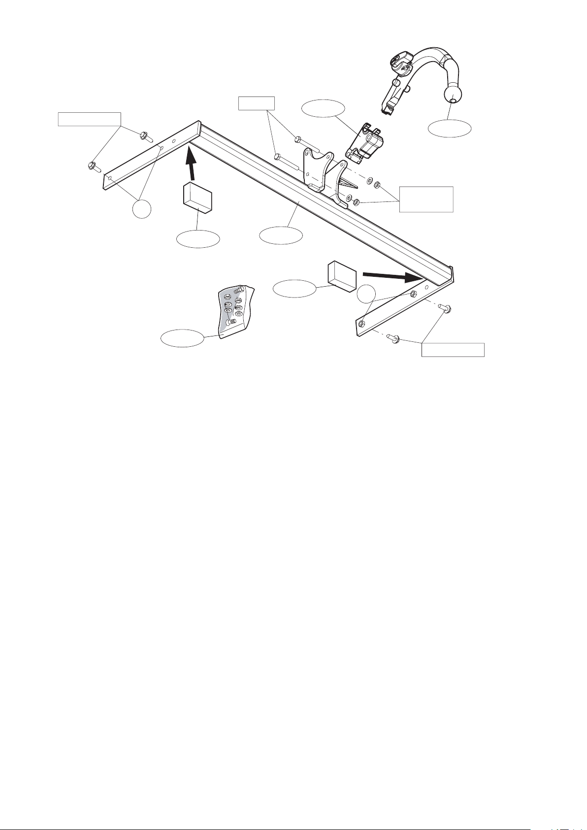
Se skissen för montering och monteringsmaterial.
Se verkstadshandboken för demontering och montering av fordonets
delar.
Se de bifogade monteringsanvisningarna för montering och demon-
tering av det löstagbara kulsystemet.
MONTAGEVEJLEDNING:
1. Demonter baglysenhederne.
2. Demonter kofangeren.
3. Demonter køretøjets tværvange (Sæt bolte på plads igen).
4. Sav den angivne del ud af kofangeren ved hjælp af skabelonen.
5. Fjern tapen ved montagepunkterne.
6. Monter anhængertrækket i chassiset.
7. Spænd alle bolte og jf. tabellen.
8. Anbring de to PE-skumblokke som afdækning i chassisvangerne.
9. Monter kuglehuset.
10.Spænd alle bolte og møtrikker jf. tabellen.
11.Monter kofangeren.
12.Monter baglysenhederne.
Rådfør for montage og montagemidler skitsen.
Rådfør for demontering og montage af dele til køretøjet arbejdsp-
ladshåndbogen.
Rådfør for montage og demontering af det aftagelige kuglesystem
den vedlagte montagevejledning.
© 451770/15-02-2005/5
S
DK
OBS:
* Kontakta återförsäljaren om fordonet eventuellt bör modifieras.
* Om det finns ett bitumen- eller stötdämpande lager vid kontaktytor skall
detta avlägsnas.
* Kontakta din återförsäljare för ditt fordons max. dragvikt och tillåtna kult-
ryck.
* Vid borrning skall man se till att elektrisk-, broms- og bränsleledningar-
na inte skadas.
* Avlägsna de små plastlocken - om dessa finns - från punktsvetsmuttrar-
na.
* Efter att draget är monterat, placera monteringsanvisningen tillsam-
mans bilens övriga dokument.
BEMÆRK:
* Kontakt forhandleren i forbindelse med eventuelle påkrævede
ændring(er) på køretøjet.
REMARQUE:
* Pour une/des adaptations indispensables sur le véhicule, veuillez con-
sulter le concessionnaire.
* Enlever la couche de bitume ou d'anti-tremblement qui recouvre éven-
tuellement les points de fixation.
* Pour connaître le poids de traction maximum et le poids en flèche sur la
rotule autorisée du véhicule, veuillez consulter votre concessionnaire.
* Veiller en perçant à ne pas endommager les conduites de électrique, de
frein et de carburant.
* Retirer "si présents" les embouts en plastique des écrous de soudure
par point.
* Cette notice de montage doit être conervée à bord du véhicule après
montage de l'attelage.
INSTRUCCIONES DE MONTAJE:
1. Desmontar las unidades de las luces traseras.
2. Desmontar el parachoques.
3. Desmontar el travesaño del vehículo (volver a colocar tornillos).
4. Serrar la parte indicada del parachoques con ayuda de la plantilla.
5. Retirar la cinta adhesiva a la altura de los puntos de fijación.
6. Montar el gancho de remolque en el chasis.
7. Apretar todos los tornillos de acuerdo con los puntos de la tabla.
8. Instalar los dos bloques de espuma PE para sellar los largueros del
chasis.
9. Montar la caja de la bola.
10.Apretar todos los tornillos y tuercas de acuerdo con los puntos de la
tabla.
11.Montar el parachoques.
12.Montar las unidades de las luces traseras.
Consultar el croquis para el montaje y medios de fijación.
Consultar para el desmontaje y montaje de piezas del vehículo el
manual de instalación de taller.
Consultar para el montaje y desmontaje del sistema de la bola extraí-
ble las instrucciones de montaje adjuntas.
ISTRUZIONI PER IL MONTAGGIO.:
1. Smontare i gruppi dei fanali posteriori.
2. Smontare il paraurti.
3. Smontare la traversa dal veicolo (rimontare bulloni).
4. Con l’ausilio della sagoma, segare via dal paraurti la parte indicata.
5. Rimuovere il nastro adesivo in corrispondenza dei punti di fissaggio.
6. Montare il gancio traino sul telaio.
7. Serrare tutti i bulloni alle coppie di serraggio indicate in tabella.
8. Inserire i due blocchi di polistirolo espanso nei montanti del telaio per
chiuderli.
9. Montare l’alloggiamento della sfera.
10.Serrare tutti i dadi e bulloni alle coppie di serraggio indicate in tabella.
11.Montare il paraurti.
12.Montare i gruppi dei fanali posteriori.
Consultare il disegno per il montaggio ed i dispositivi di fissaggio.
Per lo smontaggio ed il montaggio dei componenti del veicolo con-
sultare il manuale tecnico dell’officina.
Per il montaggio e lo smontaggio del sistema a sfera rimovibile, con-
sultare le istruzioni di montaggio allegate.
© 451770/15-02-2005/6
* Si en los puntos de fijación hay una capa de betún o anti-choque hay
que quitarla.
* Consulte a su concesionario para el peso máximo de tracción y la pre-
sión de la bola admitida de su vehículo.
* No agujerear cable de eléctrico, tubos de freno o gasolina"
* Retirar, si presentes, los capuchones de plástico de las tuercas de sol-
dadura por punto.
* Guarde estas instucciones junto a la documentación del veículo des-
pués del montaje del enganche.
I
E
* Undervognsbehandlingen skal fjernes de steder hvor trækket ligger an
mod bilen.
* Kontakt Deres forhandler for oplysninger om den maksimale trækkraft
og det tilladte kugletryk.
* Vær forsigtig ikke at bore i ledninger-,bremse elller benzinslange
* Fjern plasticpropperne "om de findes" fra de punktsvejsede m¢trikker.
* DENNE MONTERINGSVEJLEDNING SKAL MEDBRINGES VED SYN.
N.B.:
* Para (una) eventual(es) adaptación(es) 'del vehículo' consúltese al
concesionario.
N.B.:
* Per eventuali necessari adattamenti "del veicolo" si consiglia di consul-
tare il fornitore.
Place on inside bumper
153
154
CENTERLINE BUMPER
451700 BUMPER TEMPLATE:
AUDI A3 Sportback
2005->
CUT OUT
BUMPER EDGE

Other Brink Automobile Accessories manuals

Brink 756843 User manual

Brink

Brink 756843 User manual

Brink 5545 User manual

Brink

Brink 5545 User manual

Brink 3615 User manual

Brink

Brink 3615 User manual

Brink 5377 User manual

Brink

Brink 5377 User manual

Brink 6186 User manual

Brink

Brink 6186 User manual

Brink 701484 User manual

Brink

Brink 701484 User manual

Brink 6193 User manual

Brink

Brink 6193 User manual

Brink 709553 User manual

Brink

Brink 709553 User manual

Brink ARB 2800 User manual

Brink

Brink ARB 2800 User manual

Brink 4487 User manual

Brink

Brink 4487 User manual

Brink 4281 User manual

Brink

Brink 4281 User manual

Brink 6194 User manual

Brink

Brink 6194 User manual

Brink 5064 User manual

Brink

Brink 5064 User manual

Brink 6059 User manual

Brink

Brink 6059 User manual

Brink 6185 User manual

Brink

Brink 6185 User manual

Brink 6020 User manual

Brink

Brink 6020 User manual

Brink 6579 User manual

Brink

Brink 6579 User manual

Brink 3275 User manual

Brink

Brink 3275 User manual

Brink 6335 User manual

Brink

Brink 6335 User manual

Brink 6404 User manual

Brink

Brink 6404 User manual

Brink 756844 User manual

Brink

Brink 756844 User manual

Brink 5320 User manual

Brink

Brink 5320 User manual

Brink 4767 User manual

Brink

Brink 4767 User manual

Brink 701513 User manual

Brink

Brink 701513 User manual

Popular Automobile Accessories manuals by other brands

Twinny Load A 26 Fitting instructions

Twinny Load

Twinny Load A 26 Fitting instructions

Seat 5FJ.071.691 installation instructions

Seat

Seat 5FJ.071.691 installation instructions

Westin 27-1585 instructions

Westin

Westin 27-1585 instructions

Scosche GOBAT 2600 PBC71 quick start guide

Scosche

Scosche GOBAT 2600 PBC71 quick start guide

Pittman Outdoors PPI-CARMAT owner's manual

Pittman Outdoors

Pittman Outdoors PPI-CARMAT owner's manual

ACME CH106 manual

ACME

ACME CH106 manual

travall TDG 1512 Fitting instructions

travall

travall TDG 1512 Fitting instructions

Compass 238 270 instruction manual

Compass

Compass 238 270 instruction manual

Thule Rapid System 1550 instructions

Thule

Thule Rapid System 1550 instructions

Axxess AX-LR90082 installation instructions

Axxess

Axxess AX-LR90082 installation instructions

Dakota Digital LED Tail Lights LAT-NR161 installation instructions

Dakota Digital

Dakota Digital LED Tail Lights LAT-NR161 installation instructions

Nav TV NTG3 Product description

Nav TV

Nav TV NTG3 Product description

Saris 4425 manual

Saris

Saris 4425 manual

Safe Fleet Prime Design VBB FT21B manual

Safe Fleet

Safe Fleet Prime Design VBB FT21B manual

Westport Fuel Systems installation manual

Westport

Westport Fuel Systems installation manual

FACTORY UTV Dual Clamp Spare Tire Mount installation guide

FACTORY UTV

FACTORY UTV Dual Clamp Spare Tire Mount installation guide

Car-Interface v.LINK VL2-MIB-3 manual

Car-Interface

Car-Interface v.LINK VL2-MIB-3 manual

Brodit ProClip 854740 manual

Brodit

Brodit ProClip 854740 manual

manuals.online logo
manuals.online logoBrands
  • About & Mission
  • Contact us
  • Privacy Policy
  • Terms and Conditions

Copyright 2025 Manuals.Online. All Rights Reserved.