manuals.online logo
Brands
  1. Home
  2. •
  3. Brands
  4. •
  5. Flycolor
  6. •
  7. Controllers
  8. •
  9. Flycolor 4in1-30A User manual

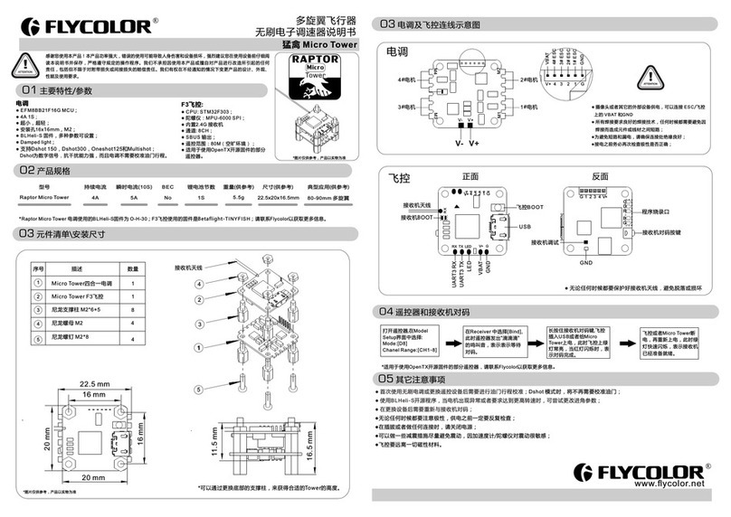
Flycolor 4in1-30A User manual

10BL388
*All pictures are for reference only
4 i n 1
BLHeli
02 Specification
04 Wiring diagram
四合一电调
4in1 ESC
飞控
Flight control
尼龙螺母 M3
Nylon Nut M3
尼龙支撑柱 M3*6+6
Nylon spacer M3*6+6
1
2
3
4
5
尼龙螺钉 M3*10
Nylon screw M3*10
03 Part list / Dimensions
Item
1
2
3
4
5
Description Qty.
1
1
4
4
4
GND
Battery Voltage
BATV
GND
+5V+5V
SConnect to the Camera or
AV transmitter single cable
-
-MA
MB
MC
Motor A
Motor B
Motor C
V -
V + Battery+
Battery-
16.5±0.5
90
33
3
30±0.5
30±0.5
安装尺寸 Installation dimension
12V
BATV
-(GND)
-(GND)
+5V
S
V+
V -
+
-
MA
MB
MC
MA
MB
MC
MA
MB
MC
MA
MB
MC
-(GND)
BATV
-(GND)
+5V
S
102
43
屏蔽线
Shield cable
61
6
ATTENTION
S-FW020004-D
4in1-20A 20A 30A 2-4S 47.2g 210-330 Multi
5V/3A,12V/1A 102x43x15mm
S-FW020004-D
4in1-30A 30A 40A 2-4S 102x43x15mm
47.2g 210-450 Multi
5V/3A,12V/1A
Con. Current Burst Current
(10S) BEC Size
Weight
LiPo cells
Manufacture Model Typical Applications
(For reference)
Model
*All pictures are for reference only
Please ensure all solder joints are insulated with heat shrink where necessary.
Battery Voltage
BATV
GND
+5V+5V
S
12V
-
12V
GND
-
Connect to the Camera or
AV transmitter single cable
The anti-interference ability of some camera and AV transmitter
is not strong, easily affected by external interference. In
order to improve the anti-interference ability, we will
provide a shield cable additional, you could:
1.Directly connect with the connecting line between the
camera and the AV transmitter.
2.If you chose the join points “S”for camera and AV
transmitter, you can connect the shield cable to the join
points on the PCB, see the figure right side.
(Please check to ensure no short circuit after welding )
12V
BATV
-(GND)
-(GND)
+5V
S
-(GND)
BATV
-(GND)
+5V
S
Sprial shield connect GND“ ”-
Conductor connect “S”Conductor connect “S”
Sprial shield connect GND“ ”-
,
ATTENTION
Thank you for purchasing our brushless electronic speed controller (ESC) . Any Improper operationmay cause personal injury damage
to the product and related equipments. This high power systemfor RC model can be dangerous ,we strongly recommend reading the
user manual carefully and completely. We will not assume any responsibility for any losses caused by unauthorized modifications
to our product. We have the right to change the design, appearance, performance and usage requirements of the product without
notice.
1.Highly integrated Power Supply Board / ESC / Flight Control, All of them can be separately removed for maintenance, upgrade
faster and more convenient. light weight, good performance.
2.Plug type F3 flight control, anti plug, convenient and fast for installation. Flight control with a buzzer for Alarm.
3.Dedicated drive IC, faster response, smaller and lighter.
4.Power supply board integrated 12V/1A ,5V/3A and battery voltage (BATV) power supply, could supply different voltages for
Camera, AV transmitter and LEDs.
5.No signal cable, maximum extent reduces the crosstalk caused by signal transmission, and makes flight more stable.
6.No power supply wire for flight control , no voltage detection wire and Alarm cable, make the overall weight lighter, install
faster, more convenient.
7. compatible with “regular" signal-receiving mode and “Oneshot125”signal-receiving mode (throttle signals range fromESC
125μs~250μs).
8.Use BLHeli open-source firmware, can update the firmware or write setup via signal cable; Using “Damped light” mode , it
improves the throttle response, when reducing the throttle amount, the Motors slow down rapidly. It strengthens the stability
and flexibility of multi-rotors, quite suitable for QAVs.
01 Main features
User Manual
Multi-Rotor Brushless ESC
251400-1043-EN, V 1.1
Shenzhen Flycolor Electronic Co.,Ltd
TEL:0755-86321853 FAX:0755-86321852
Web: www.flycolor.net Email: sales@flycolor.net
TX R X
TX R X
GPS
RX T X 5V GND
OSD LED
GN D 5V
GN D 5V DI N 5V GND
1
8
8
1
RX T X + - RX TX + -
Buzzer
蜂鸣器
+-
Receiver
接收机
6
5
4
3
2
1
6
5
4
3
2
1
3
4
3
4
Receiver
接收机
7 LED
7
USB
PWM mode
TX R X
TX R X
GPS
RX T X 5V GND
OSD LED
GN D 5V
GN D 5V DIN 5V G ND
1
8
8
1
RX T X + - RX TX + -
Buzzer
蜂鸣器
+-
PPM Receiver
接收机
3
2
1
7 LED
7
USB
PPM mode
PPM
TX RX
TX RX
GPS
RX TX 5V GND
OSD SBUS
Receiver
GND 5V
GND 5V SBUS
1
8
8
1
RX TX + - RX TX + -
Buzzer
蜂鸣器
LED
2
1
7
USB
SBUS mode DIN
5V
GND
SBUS 接收机
+ -
F3 flight control modes
Default values are marked in dark gray.
*:Only enabled for some ESCs. From code rev 14.4, damped light is default on the ESCs that support it. For prior code revisions, high is default.
**: Default startup power varies by ESC. Generally the default power is lower for larger ESCs.
***:For code revs 14.4 and before, dither range was 7/15/31/63.
Function
1 - Closed loop P gain
2 - Closed loop I gain
3 - Closed loop mode
4 - Multi gain
5 - Startup power**
6 - Commutation timing
7 - Pwm frequency
8 - Pwm dither***
9 - Demag compensation
10 - Rotation direction
11 - Input pwm polarity
0.13
0.13
HiRange
0.75
0.031
Low
High
Off
Off
Normal
Positive
0.17
0.17
MidRange
0.88
0.047
MediumLow
Low
3
Low
Reversed
Negative
0.25
0.25
LoRange
1.00
0.063
Medium
*DampedLight
7
High
Bidirectional
0.38
0.38
Off
1.12
0.094
MediumHigh
/
15
/
/
//
0.50
0.50
1.25
0.125
High
31
/
/
/
/
/
0.75
0.75
0.188
1.00
1.00
0.25
1.5
1.5
0.38
2.0
2.0
0.50
3.0
3.0
0.75
4.0
4.0
1.00
6.0
6.0
1.25
8.0
8.0
1.50
/
/
/
/
/
/
/
/
/
/
/
/
/
/
/
/
/
/
/
/
/
/
/
/
/
/
/
/
/
/
/
/
/
/
/
/
/
/
/
/
/
/
/
/
/
/
/
/
/
/
/
/
/
/
/
/
/
/
/
/
/
/
/
/
/
/
/
/
/
/
/
/
/
/
/
/
123456789 10 11 12 13
1. Closed loop P gain sets the proportional gain for the rpm control loop. This setting controls the gain from speed error to motor power.
2. Closed loop I gain sets the integral gain for the rpm control loop. This setting controls the gain from integrated speed error (summed over time) to motor power.
3. Closed loop mode sets the range of speeds that the control loop can operate on.
- For the high range, throttle values from 0% to 100% linearly correspond to rpm targets from 0 to 200000 electrical rpm
- For the middle range, throttle values from 0% to 100% linearly correspond to rpm targets from 0 to 100000 electrical rpm
- For the low range, throttle values from 0% to 100% linearly correspond to rpm targets from 0 to 50000 electrical rpm
- When closed loop mode is set to off, the control loop is disabled.
4.Multi gain scales the power applied to the motor for a given input. Note that this is only for PWM input, for PPM input it has no effect. Beware that a low multi gain will also limit the maximum power to the motor.
5. Startup is always done with the direct star tup method, which runs the motor using back emf detection from the very star t. In this mode power is given by the throttle used, but limited to a maximum level.
This maximum level can be controlled with the startup power parameter. Beware that setting startup power too high can cause excessive loading on ESC or motor!
6. Commutation timing can be adjusted in three steps. Low is about 0°, mediumlow 8°, medium 15°, mediumhigh 23° and high 30°. Typically a medium setting will work fine, but if the motor stutters it can be
beneficial to change timing.
7.Pwm frequency:
-High: High pwm frequency is around 20kHz.
-Low: Low pwm frequency is around 8kHz.
-Damped light : This mode adds loss to the motor for faster retardation. Damped light mode always uses high pwm frequency. This mode is only suppor ted on some ESCs (where fet switching is sufficiently fast).
8.Pwm dither is a parameter that adds some variation to the motor pwm off cycle length. This can reduce problems (like throttle steps or vibration) in rpm regions where the pwm frequency is equal to harmonics of
the motor commutation frequency, and it can reduce the step to full throttle. It is primarily beneficial when running damped light mode. Dither is not applied in closed loop mode.
9.Demag compensation is a feature to protect from motor stalls caused by long winding demagnetization time after commutation. The typical symptom is motor stop or stutter upon quick throttle increase,
particularly when running at a low rpm. As described earlier, setting high commutation timing normally helps, but at the cost of efficiency.
Generally, a higher value of the compensation parameter gives better protection. If demag compensation is set too high, maximum power can be somewhat reduced.
10. The rotation direction setting can be used to reverse motor rotation.
11.The input pwm polarity setting can be used to inverse the throttle behaviour. This is intended to be used with receivers that provide negative pwm. When using PPM input it must be set to positive.
Programming parameters that can only be accessed from configuration software (BLHeliSuite):
- Throttle minimum and maximum values for PPM input (will also be changed by doing a throttle calibration).
- Throttle center value for bidirectional operation with PPM.
- Beep strength, beacon strength and beacon delay.
- Programming by TX. If disabled, the TX can not be used to change parameter values (default is enabled).
- Thermal protection can be enabled or disabled (default is enabled).
Temperature is above 140℃, motor power is limited to 75%;Above 145℃, motor power is limited to 50%;Above 150℃, motor power is limited to 25%.Above 155℃, motor power is limited to 0%.
- PWM input can be enabled or disabled (default is disabled). If disabled, only 1-2ms PPM and 125-250us OneShot125 are accepted as valid
input signals.
- Power limiting for low RPMs can be enabled or disabled (default is enabled). Disabling it can be necessary in order to achieve full power on some low kV motors running on a low supply voltage. However, disabling
it increases the risk of toasting motor or ESC.
- Brake on stop can be enabled or disabled (from rev14.5 ,default is disabled),When enabled, brake will be applied when throttle is zero. For nonzero throttle, this setting has no effect.
Programming parameters below in table that can be accessed from the flight control parameter software via computer or configuration software (BLHeliSuite):
05 Programming parameter value
07 Notice
● After the ESC connected to the flight system, it will automatically detect the input throttle signals every time it powered on, and then execute the corresponding signal-receiving mode.
● User need to calibrate the throttle range when star ting to use a new ESC or another transmitter.
● BLHeli open-source firmware, when some abnormality occurs in ESC driving the motor or need the motor to reach a higher RPM, user can try to change the timing.
● User also can connect the flight control to the computer to update the firmware or change the setup via .configuration software (BLHeliSuite)
● Please contact Flycolor sales or technical support for more information.
This manual suits for next models

2

Other Flycolor Controllers manuals

Flycolor Raptor S-Tower-12A-OSD User manual

Flycolor

Flycolor Raptor S-Tower-12A-OSD User manual

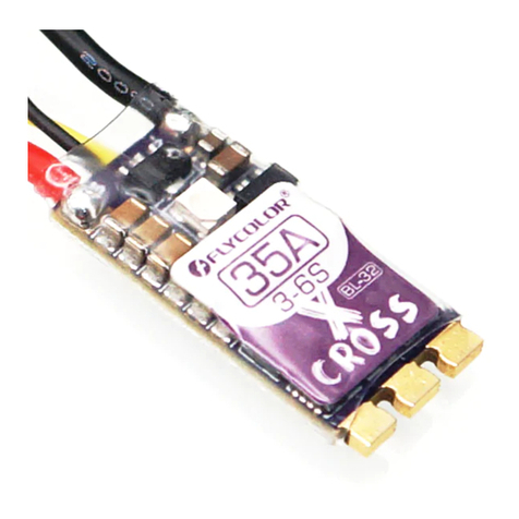
Flycolor X-CROSS BL-32 User manual

Flycolor

Flycolor X-CROSS BL-32 User manual

Flycolor RAPTOR BLS-Mini User manual

Flycolor

Flycolor RAPTOR BLS-Mini User manual

Flycolor Raptor390 Tower-20A User manual

Flycolor

Flycolor Raptor390 Tower-20A User manual

Flycolor Raptor390 4in1-20A User manual

Flycolor

Flycolor Raptor390 4in1-20A User manual

Flycolor Kraken 40A Wifi User manual

Flycolor

Flycolor Kraken 40A Wifi User manual

Flycolor X-Tower BL-32 4in1-40A User manual

Flycolor

Flycolor X-Tower BL-32 4in1-40A User manual

Flycolor Raptor 390Tower-20A User manual

Flycolor

Flycolor Raptor 390Tower-20A User manual

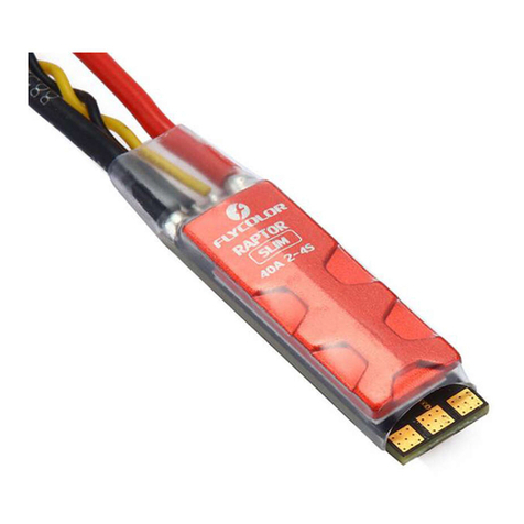
Flycolor Raptor SLIM-40A User manual

Flycolor

Flycolor Raptor SLIM-40A User manual

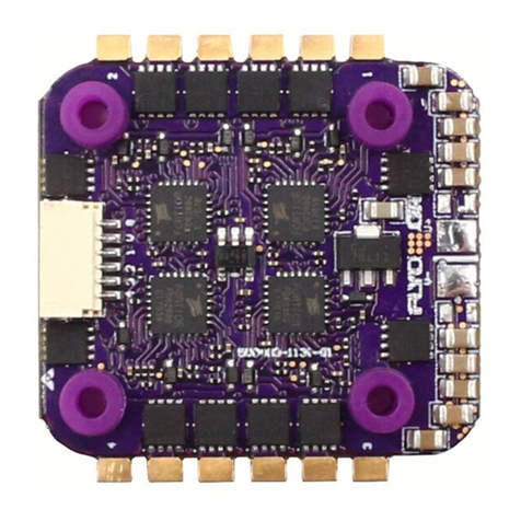
Flycolor Raptor Micro Tower User manual

Flycolor

Flycolor Raptor Micro Tower User manual

Flycolor Raptor BLS-Pro-20A User manual

Flycolor

Flycolor Raptor BLS-Pro-20A User manual

Flycolor X-Cross BL-32 User manual

Flycolor

Flycolor X-Cross BL-32 User manual

Flycolor Raptor S-Tower-20A User manual

Flycolor

Flycolor Raptor S-Tower-20A User manual

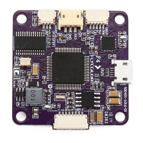
Flycolor X-Tower F4 FC User manual

Flycolor

Flycolor X-Tower F4 FC User manual

Flycolor Raptor S-Tower F4-20A User manual

Flycolor

Flycolor Raptor S-Tower F4-20A User manual

Flycolor Raptor S-Tower F4 User manual

Flycolor

Flycolor Raptor S-Tower F4 User manual

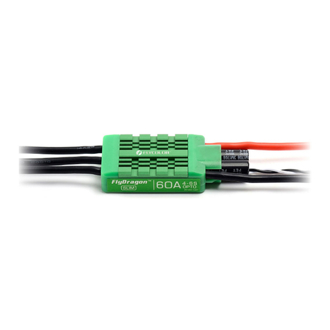
Flycolor FlyDragon SLIM-60A User manual

Flycolor

Flycolor FlyDragon SLIM-60A User manual

Flycolor X-Tower F4-40A User manual

Flycolor

Flycolor X-Tower F4-40A User manual

Flycolor Raptor S-Tower 20A F4 FC User manual

Flycolor

Flycolor Raptor S-Tower 20A F4 FC User manual

Flycolor Raptor BLS Series User manual

Flycolor

Flycolor Raptor BLS Series User manual

Flycolor Raptor BLS 4in1-20A User manual

Flycolor

Flycolor Raptor BLS 4in1-20A User manual

Flycolor Raptor390 Tower F3 FC User manual

Flycolor

Flycolor Raptor390 Tower F3 FC User manual

Flycolor Raptor S-Tower-30A User manual

Flycolor

Flycolor Raptor S-Tower-30A User manual

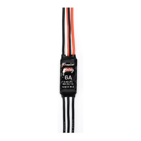
Flycolor Fairy-6A User manual

Flycolor

Flycolor Fairy-6A User manual

Popular Controllers manuals by other brands

Panasonic AKHRP900P - CAMERA CONTROLLER HC Service manual

Panasonic

Panasonic AKHRP900P - CAMERA CONTROLLER HC Service manual

PhaseOne PAS Pod Operation guide

PhaseOne

PhaseOne PAS Pod Operation guide

Truma SecuMotion Operating instructions & installation instructions

Truma

Truma SecuMotion Operating instructions & installation instructions

OTEK FS Series quick start guide

OTEK

OTEK FS Series quick start guide

lapara AVR-2000 user manual

lapara

lapara AVR-2000 user manual

Reely 1600323 operating instructions

Reely

Reely 1600323 operating instructions

bonitron M3534-I3 Customer Reference Manual

bonitron

bonitron M3534-I3 Customer Reference Manual

Lenze 3200 C Series Mounting instructions

Lenze

Lenze 3200 C Series Mounting instructions

ChronTrol XT Series user guide

ChronTrol

ChronTrol XT Series user guide

Quickie R-net user manual

Quickie

Quickie R-net user manual

JETI model SPIN 11 manual

JETI model

JETI model SPIN 11 manual

Siemens FDV241 Startup manual

Siemens

Siemens FDV241 Startup manual

Mitsubishi Electric MELSEC-A Series user manual

Mitsubishi Electric

Mitsubishi Electric MELSEC-A Series user manual

Westinghouse IWB-PC02 user manual

Westinghouse

Westinghouse IWB-PC02 user manual

RoboteQ MDC1230 manual

RoboteQ

RoboteQ MDC1230 manual

Vacon NX user manual

Vacon

Vacon NX user manual

Sentera Controls STR-1 Mounting and operating instructions

Sentera Controls

Sentera Controls STR-1 Mounting and operating instructions

Datakom D-200 MK2 user manual

Datakom

Datakom D-200 MK2 user manual

manuals.online logo
manuals.online logoBrands
  • About & Mission
  • Contact us
  • Privacy Policy
  • Terms and Conditions

Copyright 2025 Manuals.Online. All Rights Reserved.