ATTENTION
ATTENTION
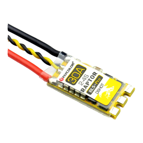
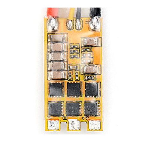
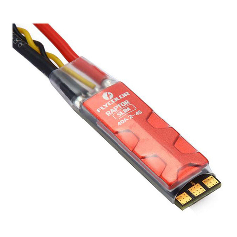
ESC
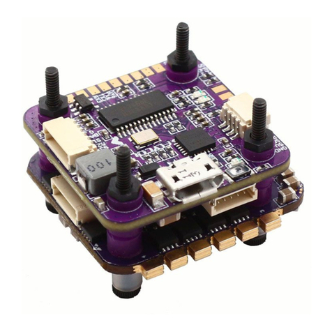
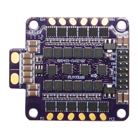
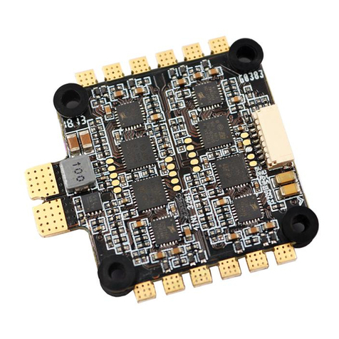
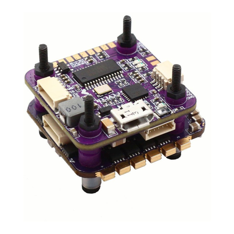
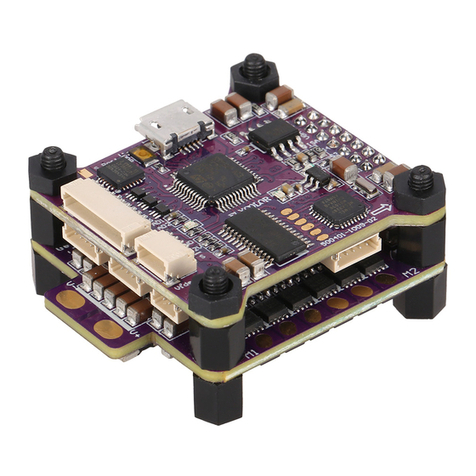
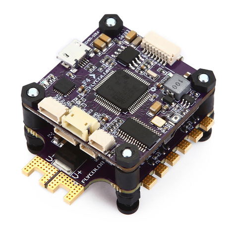
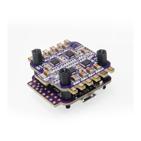
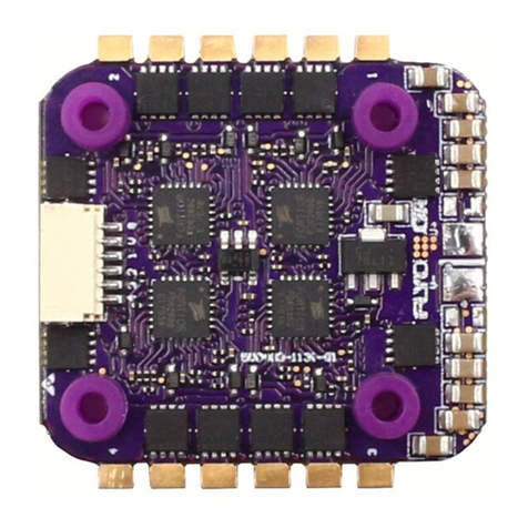
Micro Tower 4in1 ESC
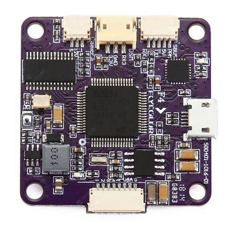
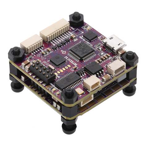
Micro Tower F3 F.C
1
1
8
4
4
2
3
4
5
1
06 Other Attention
F.C
1
2
4
3
5
Raptor Micro Tower
RAPTOR
Tow e r
Micro
ESC
● EFM8 BB21F16G M C U;
● 4A 1S;
● Extra sm all, ultra ligh;
● 16x16mm,M2;Mounting Hole:
● BLHeli-S ;Multiple parameters can be setfirmware
● Damped light;
● Support Dshot150,Dshot300, Oneshot125 and M ultishot;
Dshot is d igital signal, anti-interference ability is stronger,
and do not need throttle calibration.
02 Specification
Raptor Micro Tower 4A 5A 1S 5.5g 80-90mm Multi
No 22.5x20x16.5mm
*Raptor Micro Tower is using O-H-30 BLHeli-S firmware;F3 Flight control is using Betaflight-TINYF I SH firmware;
Please contact Flycolor for more information。
F3 Flight control:
CPU: S T M32F303;●
Gyro:M P U-6000 SPI;●
Built-in 2.4G Receiver;●
Channel: 8C H;●
SBUS Output;●
Control Range:80M ;● (Open environment)
Compatible with remote control●
(Transmitter) which using Open TX firmware.
11.5 mm
16.5 mm
22.5 mm
20 mm
20 mm
16 mm
16 mm
V+
V-
3#Motor 1#Motor
4#Motor
M1
2#Motor
V- V+
M2
M3
M4
V+ 4 32 1 G
VBAT
3# ES C
4# ES C
2# ES C
1# ES C
GND
UART3 RX
UART3 TX
LED
VBAT
GND
USB
LED
RX
TXRX G
V+
V+432 1 G
G
B
R
D
C
GV+4
3
21
GND
Receiver
Programming
Turn on remote control,
at Model Setup interface
to select :
Mode:[D8]
Chanel Range:[CH1-8]
05 Remote control & Receiver Binding
www.flycolor.net
●Protect the receiver antenna at all times to avoid shedding or damage.
*Compatible with Remote Control(Transmitter) which using OpenTX firmware, please contact Flycolor for m ore information.
User Manual
Multi-Rotor Brushless ESC
Thank you for using our product. Any Improper operation may cause personal injury damage to the product
and related equipments. This high power system for RC model can be dangerous ,we strongly recommend reading
the user manual carefully and completely. We will not assume any responsibility for any losses caused by
unauthorized modifications to our product. We have the right to change the design, appearance, performance
and usage requirements of the product without notice.
BECCon. Current Burst Current
(10S)
Size
(For reference)
Weight
(For reference)
LiPo cells Typical Applications
(For reference)
Model
Nylon spacer M2*6+5
Nylon screw M2*8
Qty.
Nylon Nut M2
Item Description Receiver antenna
*All pictures are for re ference only
*All pictures are for re ference only
*The appropriate he ig ht of the Tower can be obtaine d by
replacing the nylon s pacer at the bottom
03 Part list / Dimensions
01 Main features
04 Connection diagram
●Connect the VB AT&GND on the ESC or Flight Control
to supply powered for cameras or other external devices.
All welding requires good welding technology, short circuit ●
between the element or the wire should be avoided at any time.
Please ensure all solder joints are insulated with heat shrink●
where necessary.
●Please double-check the polarity is correct before power up.
Top Bottom
FC Boot
Receiver Boot
Receiver antenna
Receiver Bind
Rceiver Debug
Hold the receiver Bind Bu tton on FC,
Then connect the U SB or supply
power to Micro Towe r. The green LED
will lights all time, then the red LED
flashing means that th e binding
is completed.
Select [Bind] and enter,
the remote control emits
"beep-beep-beep"sound,
it means that wait for bi nding.
F.C or Micro Tower
power off, then power on
again, the green LED
flashes rapidly to indicate
the receiver is ready.
● User need to calibrate the throttle range when starting to use a new E S C or another transmitter. When the input signal is Dshot,
throttle calibration is disabled.
● BLHeli-S open-source firmware, when some abnormality occurs in ESC driving the motor or need the motor to reach a higher R P M,
user can try to change the timing.
● Re-binding the receiver and remote control (Transmitter) after changing device.
● Observe polarity at all times. Check and double check before applying power.
● Power off before unplugging ,plugging in or making any connections.
● Keep magnets away from the Flight Controller.
● Do everything you can to prevent vibrations.
251400-1077,V1.0
