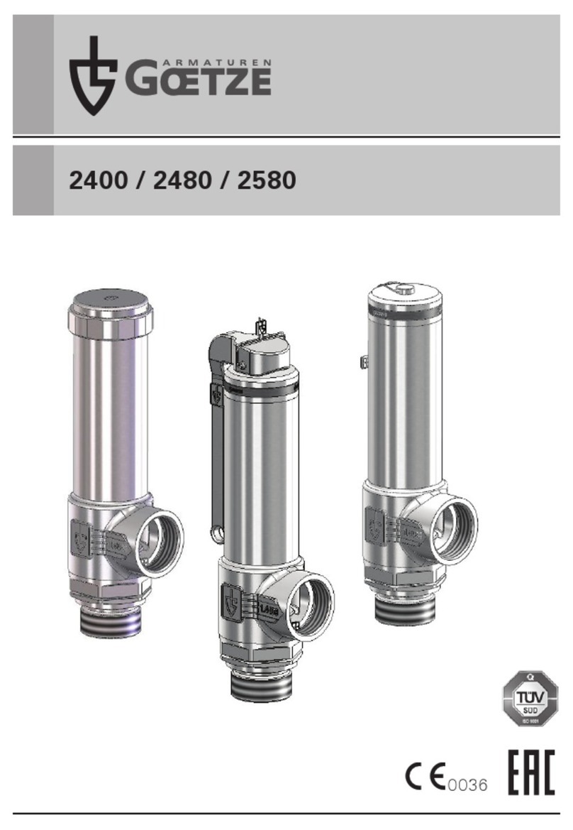
Goetze 4000 User manual

0036
www.goetze-armaturen.deAssembly and maintenance instructions - 4000
4000
TS

www.goetze-armaturen.deAssembly and maintenance instructions - 4000
a)
b) c)
Pmax = 6 bar

www.goetze-armaturen.deAssembly and maintenance instructions - 4000
d)
f) g)
e)

h) i)
www.goetze-armaturen.deAssembly and maintenance instructions - 4000

1Allgemeine Sicherheitshinweise
www.goetze-armaturen.deAssembly and maintenance instructions - 4000
Montage-, Wartungs- und Betriebsanleitung
Sicherheitsventil 4000
•Benutzen Sie das Ventil nur:
- bestimmungsgemäß
- in einwandfreiem Zustand
- sicherheits- und gefahrenbewusst
•Die Einbauanleitung ist zu beachten.
•Alle Schutzkappen und andere Transportsicherungen sind direkt vor der
Montage zu entfernen.
•Zusätzlich zu den allgemein gültigen Montagerichtlinien ist zu beachten, dass
vor Demontage des Sicherheitsventils die Anlage drucklos gemacht werden
muss. Darüber hinaus muss die Anlage entleert und bei aggressiven und
ätzenden Medien belüftet werden. Das Sicherheitsventil sollte Raumtempera-
tur angenommen haben.
•Störungen, welche die Sicherheit beeinträchtigen können, sind umgehend zu
beseitigen.
•Das Sicherheitsventil ist ausschließlich für den in dieser Einbauanleitung
angeführten Verwendungsbereich bestimmt. Eine andere oder darüber hinaus-
gehende Benutzung gilt als nicht bestimmungsgemäß.
•Mit dem Entfernen der Plombierung erlischt die Werksgarantie.
•Alle Montagearbeiten sind durch autorisiertes Fachpersonal durchzuführen.
•Diese Betriebsanleitung ersetzt keine nationalen Vorschriften, Vorschriften
zur Unfallverhütung, sowie ortsgebundene Sicherheitsvorschriften. Diese sind
immer vorrangig zu beachten.
•Alle baulichen Veränderungen der Armatur sind strengstens verboten. Hierzu
zählen insbesondere das Anbringen von Bohrungen oder das Anschweißen von
Gegenständen.
•Bei allen Instandsetzungsarbeiten müssen folgende Punkte beachtet werden:
- Bei Reparatur- und Wartungsarbeiten an automatisierten Armaturen muss
eine sichere Unterbrechung der Energieversorgung der Antriebe gewähr-
leistet sein.
- Druckpolster in der Anlage sind abzubauen und die betroffenen Rohrleitungen
müssen entleert werden. Hierbei ist sich über Gefahren, die durch Rückstän-
de des Betriebsmediums entstehen können, zu informieren.
- Geeignete und ausreichende persönliche Schutzausrüstung ist zu tragen.
- Eine Wiederinbetriebnahme der Anlage ist durch geeignete Maßnahmen und
Mittel auszuschließen.
de
Originalsprache

www.goetze-armaturen.deAssembly and maintenance instructions - 4000
Feder-Sicherheitsventile sind im Allgemeinen mit senkrecht nach oben stehender
Federhaube einzubauen. Abweichungen von dieser Einbaulage sind im Einzelfall
möglich, bedürfen jedoch grundsätzlich der Rücksprache mit dem Herstellerwerk.
Um eine einwandfreie Funktion der Sicherheitsventile zu gewährleisten, müssen
diese so montiert werden, dass keine unzulässigen statischen, dynamischen oder
thermischen Beanspruchungen auf das Sicherheitsventil wirken können. Rohrlei-
tungen dürfen im Betrieb nur kraft- und momentfrei angeschlossen werden. Wenn
durch das Gehäuse im Ansprechfalle austretende Medium direkt oder indirekt Ge-
fahren für Personen oder die Umgebung entstehen können, so müssen geeignete
Schutzmaßnahmen getroffen werden. Dabei sind auch Ausschwadungen durch die
Entlastungsbohrungen der Federhaube zu berücksichtigen.
Zuleitung
Zuleitungsstutzen für Sicherheitsventile sollen so kurz wie möglich sein und sind
so zu gestalten, dass bei voller Ventilleistung keine höheren Druckverluste als max.
3% vom Ansprechdruck auftreten können. Der Anschluss ist zur Minimierung des
Totraums so kurz wie möglich auszuführen.
Kondensatableitung
Die Leitungen oder die Ventile selbst müssen bei möglichem Kondensatabfall an ih-
rem tiefsten Punkt mit einer ständig wirkenden Einrichtung zu Kondensatabführung
4Einbau und Montage
Einzelheiten zum Verwendungsbereich der einzelnen Ausführungen sind den
Datenblättern des Herstellers zu entnehmen. Die Beständigkeit der angegebenen
metallischen und nichtmetallischen medienberührten Materialien ist vom Betreiber
auf den jeweils vorliegenden Fall hinsichtlich des verwendeten Durchflussmedi-
ums, und/oder Reinigungsmittels zu überprüfen. Vom Anlagenbetreiber ist ein
vibrationsarmer, quasistatischer Betrieb des Ventils sicherzustellen. Ggf. sind
vom Anlagenbetreiber geeignete Maßnahmen zur Schwingungsdämpfung der
Rohrleitung zu ergreifen.
Sicherheitsventile sind hochwertige Armaturen, die besonders sorgfältig behandelt
werden müssen. Die Dichtflächen sind an Sitz und Kegel feinstbearbeitet, dadurch
wird die notwendige Dichtheit erreicht. Das Eindringen von Fremdkörpern in das
Ventil ist bei Montage und während des Betriebs zu vermeiden. Die Dichtheit eines
Sicherheitsventils kann durch Hanf, Teflonband oder anderen Dichtmitteln sowie
durch Schweißperlen u.ä. beeinträchtigt werden. Auch eine raue Behandlung des
fertigen Sicherheitsventils während Lagerung, Transport und Montage kann ein
Sicherheitsventil undicht werden lassen. Werden die Sicherheitsventile mit einem
Farbanstrich versehen, so ist darauf zu achten, dass die gleitenden Teile nicht mit
Farbe in Berührung kommen.
2Allgemeine Hinweise
3Verwendungsbereich

www.goetze-armaturen.deAssembly and maintenance instructions - 4000
versehen sein. Für eine gefahrenlose Abführung des Kondensats oder austretenden
Mediums ist zu sorgen. Die Gehäuse, Leitungen und Schalldämpfer sind gegen
Einfrieren zu sichern.
Abblaseleitung / Gegendruck
Die Abblaseleitung der Sicherheitsventile ist so auszuführen, dass beim Abblasen
der erforderliche Massestrom drucklos abgeführt werden kann. Die Abblaselelei-
tung muss zur einfachen Reinigung möglichst kurz gehalten, abbaubar oder
alternativ mit einem Gefälle von mindestens 3° in Ablaufrichtung geneigt ausgeführt
sein. Für die Montage der Zuleitung und Abblaseleitung sind ausschließlich die für
die am Ventil vorhandenen Anschlüsse passenden, genormten und für den Kontakt
mit Lebensmitteln sowie anderen sensiblen Gütern geeigneten Gegenanschlüsse
und Dichtungen zu verwenden.
Der Arbeitsdruck der Anlage soll mindestens 5% unter dem Schließdruck des
Sicherheitsventils liegen. Dadurch wird erreicht, dass das Sicherheitsventil nach
dem Abblasen wieder einwandfrei schließen kann. Bei kleineren Undichtheiten, die
durch Verunreinigungen zwischen den Dichtflächen hervorgerufen werden können,
kann das Ventil zur Reinigung durch Anlüftung zum Abblasen gebracht werden.
Kann dadurch die Undichtheit nicht beseitigt werden, liegt wahrscheinlich eine
Beschädigung der Dichtfläche vor, die nur in unserem Werk oder durch autorisierte
Fachleute repariert werden kann.
Die Anlüftung erfolgt bei Ausführung tGFP mittels Druckluftzufuhr von maximal
6 bar auf den unterhalb der Federhaube angeordneten Pneumatik-Zylinder (siehe
Abb. a). Bei Ausführung tGFL erfolgt die Anlüftung mittels Handhebel. Bei Ausfüh-
rung tGFO (gasdicht, ohne Anlüftung) ist keine Anlüftung möglich.
Sicherheitsventile ohne Anlüftung und mit gasdichter Kappe (Abb. b)
Bei Sicherheitsventilen ohne Anlüftung kann zusätzlich durch Demontieren der Ven-
tilklammer zwischen Ventilgehäuse und Federhaube das gesamte Oberteil aus dem
Gehäuse herausgezogen und eventueller Rückstand auf Sitz- und Kegeldichtung
entfernt werden. Es wird empfohlen das Ventil durch Aufbringen von Steuerluft-
druck in Offenstellung zu bringen, um die De-/ Montage zu erleichtern.
Sicherheitsventile mit pneumatischer Anlüftung (Abb. c)
Bei Sicherheitsventilen mit pneumatischer Anlüftung, kann zusätzlich durch
Demontieren der Ventilklammer zwischen Ventilgehäuse und Pneumatik-Zylinder,
das gesamte Oberteil aus dem Gehäuse herausgezogen und eventueller Rückstand
auf Sitz- und Kegeldichtung entfernt werden. Es wird empfohlen das Ventil durch
Aufbringen von Steuerluftdruck in Offenstellung zu bringen, um die De-/ Montage
zu erleichtern.
5Betriebsweise / Wartung

www.goetze-armaturen.deAssembly and maintenance instructions - 4000
Anzugsmomente Ventilklammern
Baureihe 4000
DN Gewinde Nm
25 M4 1,0
40 M5 2,5
50 M6 4,0
65 M8 12,0
80 M10 25,0
100 M12 40,0
Anlüftung zur Wartung
Bei Sicherheitsventilen mit Anlüftvorrichtung ist zu empfehlen und anlagen-
spezifisch auch Vorschrift, das Sicherheitsventil von Zeit zu Zeit durch Anlüften
zum Abblasen zu bringen, um sich von der Funktion des Sicherheitsventils zu
überzeugen. Sie lassen sich daher spätestens ab einem Betriebsdruck von ≥85%
des Ansprechdruckes zum Öffnen bringen. Eine Prüfung auf Gängigkeit der Sicher-
heitsventile hat nach TRD 601 bei Dampferzeugern mindestens in Abständen von 4
Wochen zu erfolgen. Sicherheitsventile stellen die letzte Sicherheit für den Behälter
bzw. das System dar. Sie sollen in der Lage sein, einen unzulässigen Überdruck
auch dann zu verhindern, wenn alle anderen vorgeschalteten Regel-, Steuer- und
Überwachungsgeräte versagen. Um diese Funktionseigenschaften sicherzustellen,
Montageanzugsmomente
Die nachfolgende Tabelle zeigt die zur Montage der Ventilklammer maximal zulässi-
gen Anzugsmomente:
Sicherheitsventile mit Hebel-Anlüftung (Abb. d)
Durch Demontieren der Ventilklammer zwischen Ventilgehäuse und Federhaube
kann das gesamte Oberteil aus dem Gehäuse herausgezogen und eventueller Rück-
stand auf Sitz- und Kegeldichtung entfernt werden. Es wird empfohlen das Ventil
durch Spannen des Handhebels in Offenstellung zu bringen, um die De-/ Montage
zu erleichtern. Zusätzlich ist es möglich zu Reinigungs- und Wartungszwecken den
Handhebel zu demontieren. Hierzu das separat erhältliche Montagehilfsmittel, wie
dargestellt montieren. (Abb. e) Anschließend durch Rechtsdrehung der Flügel-
mutter den Handhebel entspannen. Nun kann ein Sicherungsring vom Querbolzen
demontiert werden. Danach den Querbolzen herausdrücken, und den Handhebel
demontieren. Die Remontage findet in sinngemäß umgekehrter Reihenfolge statt.
Achtung, vor Wiederinbetriebnahme muss das Montagehilfsmittel unbedingt
wieder entfernt werden, damit die Funktion des Ventils nicht negativ
beeinträchtigt wird.
Vor Demontage ist darauf zu achten, dass das Sicherheitsventil nicht mit
Druck beaufschlagt ist. Durch wieder Anbringen des Ventiloberteils in das Gehäu-
se hat sich der Ansprechdruck des Sicherheitsventils nicht geändert.

www.goetze-armaturen.deAssembly and maintenance instructions - 4000
Um einen gleichbleibenden hygienischen Status während der gesamten Betriebs-
dauer des Ventils zu gewährleisten, sind innerhalb festgelegter Zeitabstände
Reinigungs- und ggf. Desinfektionsarbeiten durchzuführen. Die Häufigkeit der
durchzuführenden Aufgaben ist vom Betreiber anhand der Hygienestandards und
der Sensibilität der verarbeiteten Produkte, sowie der Betriebs- und Umgebungs-
bedingungen festzulegen und ist in den betriebsspezifischen Reinigungs- und /
oder Desinfektionsplan zu integrieren. Die Armatur ist nach den branchenüblichen
Verfahren und mit den dafür nötigen Reinigungsmitteln zu reinigen. Die Bestän-
digkeit der metallischen und nichtmetallischen Materialien des Ventils ist bei der
Auswahl des Reinigungs- und Desinfektionsmittels zu berücksichtigen und mit dem
Herstellerwerk abzustimmen.
Die Anlüftung des Ventils zum Zweck der CIP- oder SIP-Reinigung ist nur in Ausfüh-
rung tGFP mit pneumatischer Anlüftung oder tGFL mit Hebel Anlüftung möglich.
Bei der Ausführung mit pneumatischer Anlüftung wird das Sicherheitsventil
mittels Druckluftbeaufschlagung des Pneumatik Zylinders (Abb. a) in Offenstellung
gefahren, so dass der Ventilkegel von Reinigungsmittel, bzw. Sterilisationsdampf
umströmt werden kann. Bei geschlossenem Ventil ist die Sitz-Kegel Dichtung nicht
reinigbar, bzw. sterilisierbar. Zusätzlich zur CIP- SIP-Reinigung ist es möglich das
Ventil zu Reinigungszwecken teilweise zu demontieren. Hierzu kann nach Herstel-
lung des drucklosen Zustands, die Ventilklammer der Verbindungsstelle Gehäuse
und Federhaube gelöst werden (Abb. b bis Abb. d). Anschließend kann das komplet-
te Ventiloberteil aus dem Gehäuse herausgezogen werden. Sollte das Ventiloberteil
zu fest im Gehäuse sitzen, so ist es ggf. nötig mit Hilfe eines Schraubenziehers,
oder eines anderen geeigneten spitzen Gegenstandes das Ventiloberteil vorsichtig
aus dem Gehäuse herauszulösen (Abb. f).
Die Ventilkegelbaugruppe ist mit Hilfe eines Zylinderstiftes mit der Ventilspindel ver-
bunden. Zu Reinigungszwecken ist es möglich diese vom Ventiloberteil zu trennen.
Hierzu den O-Ring nach oben schieben, wodurch der Zylinderstift freigelegt wird.
Anschließend kann der locker sitzende Zylinderstift durch vorsichtiges Rütteln
entfernt werden. (Abb. g)
Achtung, in der Ventilkegelbaugruppe ist eine lose Kugel (Abb. h, Teil 6) verbaut,
welche während des Demontagevorgangs gegen Verlieren gesichert werden muss.
Um die Membrane, und / oder den Ventilkegel Dichtring zu tauschen, ist es möglich
6Reinigung der Armatur
bedürfen Sicherheitsventile einer regelmäßigen und wiederkehrenden Wartung.
Die Wartungsintervalle sind entsprechend den Einsatzbedingungen vom Betreiber
festzulegen. Bei Verwendung mit Lebensmitteln sowie anderen sensiblen Gütern,
sollte das Ventil regelmäßig (z.B. mehrmals pro Schicht) dahingehend überprüft
werden, ob es geöffnet bzw. angesprochen hat und ob das Produkt durch das Ventil
ausgeflossen ist. In diesem Fall muss spätestens beim nächten Reinigungsintervall
das Ventil eingehend gereinigt werden (siehe Kapitel 6 Reinigung der Armatur).
www.goetze-armaturen.deAssembly and maintenance instructions - 4000
Zusätzlich zu den allgemein gültigen Montagerichtlinien ist zu beachten, dass vor
Demontage des Sicherheitsventils die Anlage drucklos gemacht werden muss.
Darüber hinaus muss die Anlage entleert und bei aggressiven und ätzenden Medien
belüftet werden. Das Sicherheitsventil sollte Raumtemperatur angenommen haben.
7Demontage der Armatur
Reparaturen an Sicherheitsventilen dürfen nur von der Firma Goetze KG Armaturen
oder durch autorisierte Fachwerkstätten, unter ausschließlicher Verwendung von
Originalersatzteilen, durchgeführt werden.
8Reparaturen
Dieses Ventil wurde vor Verlassen des Werkes geprüft. Für unsere Produkte leisten
wir in der Weise Garantie, dass wir die Teile gegen Rückgabe kostenlos instand setzen,
die nachweislich infolge Werkstoff- oder Fabrikationsfehlern vorzeitig unbrauchbar
werden sollten. Leistung von Schadenersatz und dergleichen andere Verpflichtungen
übernehmen wir nicht. Bei Beschädigungen der Werksplombierung, unsachgemäßer
Behandlung bzw. Installation, Nichtbeachtung dieser Montage- ,Wartungs- und Be-
triebsanleitung, Verschmutzung oder normalem Verschleiß erlischt die Werksgarantie.
9Gewährleistung
die Ventilkegelbaugruppe zu demontieren (Abb. h). Hierzu sollte der Hubhilfering
(Teil 2) mit Hilfe eines geeigneten Werkzeugs (z.B. Schraubstock) an der Schlüs-
selweite gespannt werden. Anschließend durch Linksdrehung die Verschraubung
(Teil 3) lösen. Die Membrane (Teil 4) kann nun entnommen werden. Durch leichtes
Drücken auf den nach oben herausstehenden Teil des Ventilkegels (Teil 1) wird der
Dichtring (Teil 5) des Ventilkegels freigelegt, und kann gewechselt werden.
Die Remontage findet in sinngemäß umgekehrter Reihenfolge statt.
Während der Remontage ist darauf zu achten, dass:
- die Kugel in die Ventilkegelbaugruppe zwischen Kegel und Spindel eingelegt
wurde
- der Zylinderstift, welcher die Ventilkegelbaugruppe mit der Ventilspindel
verbindet eingesteckt, und durch den darüber liegenden O-Ring gegen
herausfallen gesichert ist
- die Membrane sauber in die Nut des Ventiloberteils eingelegt ist, bevor dieses
in das Ventilgehäuse eingesteckt wird (Abb. i).

12 3
4 5
76
8 9 10 11
www.goetze-armaturen.deAssembly and maintenance instructions - 4000
10 Kennzeichnung / Prüfung
Sicherheitsventile werden von uns auf Druckfestigkeit und Dichtheit geprüft, auf den
gewünschten Einstelldruck einjustiert und plombiert.
Die Kennzeichnung erfolgt unauslöschlich auf dem Typenschild bzw. auf der Federhau-
be des Ventils. Zusätzlich enthält die Kennzeichnung die notwendigen Angaben gemäß
DIN EN ISO 4126-1.
1: Ventiltyp
2: TÜV-Zeichen–Sicherheitsventil•JahrderBauteilprüfung–Prüfnummer
3: Sitzdichtungswerkstoff
4: Engster Strömungsquerschnitt
5: Ausflussziffer für Dämpfe/Gase bei 5% Öffnungsdruckdifferenz,
Leistung bei Luft (S/G = Steam/Gas)
6: Ventilhub
7: Ausflussziffer für Flüssigkeiten bei 10% Öffnungsdruckdifferenz,
Leistung bei Wasser (L = Liquids)
8: Einstelldruck
9: Minimale/Maximale Anwendungstemperatur
10: Seriennummer, hier z.B. 281711195
11: Datamatrix Code (Seriennummer)
4000tGFO EPDM ISO 4126-1TÜV-SV.18-2095
A0 = 415,5mm2S/G: 0,70 5% 3208,0 Nm3/h
L: 0,45 10% 33,1 m3/h
p.SET = 16 bar(g)
Lift = 6,6mm
-40°C / +170°C 281711195

www.goetze-armaturen.deAssembly and maintenance instructions - 4000
gemäß Anh. IV der Richtlinie 2014/68/EU
Wir, die Goetze KG Armaturen, D-71636 Ludwigsburg
erklären in alleiniger Verantwortung, dass das gelieferte Produkt:
Sicherheitsventil
auf das sich diese Erklärung bezieht, mit der Richtlinie 2014/68/EU, der DIN EN ISO
4126 sowie den nationalen Vorschriften AD 2000- A2/ A4, TRD 421/721 überein-
stimmt und folgendem Konformitätsbewertungsverfahren unterzogen wurde:
Modul B+D
Für das Ausrüstungsteil für Druckgeräte liegt eine EU-Baumusterprüfbescheinigung vor.
Die Überwachung der Qualitätssicherung Produktion erfolgt durch die TÜV SÜD
Industrie Service GmbH (0036).
Baureihe TÜV-Bauteilprüfnummer EU-Baumusterprüfung
4000 2095
Ludwigsburg, 11.04.2018
(Ort und Datum der Ausstellung)
D. Weimann
Geschäftsleitung
Konformitätserklärung

www.goetze-armaturen.deAssembly and maintenance instructions - 4000
Assembly and maintenance instructions
Safety valve 4000
•Only use the valve:
- for the intended purpose
- in satisfactory condition
- with respect for safety and potential hazards.
•Always observe the installation instructions.
•Remove all protective covers and other transport safety devices directly before
assembly.
•In addition to the generally valid assembly guidelines, you must ensure that the
system must be de-pressurised before removal of the safety valve. Moreover,
the system must be drained and ventilated in the case of aggressive and corro-
sive media. The safety valve must have adjusted to room temperature.
•Faults that may impair safety must be addressed immediately.
•The valves are exclusively intended for the application area stated in these ins-
tallation instructions. Any other or further use is not valid as the intended use.
•The manufacturer’s warranty shall be null and void if the sealed cover is
removed
•All installation work must be carried out by authorised specialist personnel only.
•These operating instructions do not replace any national regulations, regulati-
ons on accident prevention or local safety regulations. Such regulations always
have priority.
•All structural modifications of the valve are strictly prohibited. This applies in
particular to inserting drill holes or welding on other objects.
•The following points must be observed during all repair work:
- When carrying out repairs or maintenance work on automated valves, it
must be ensured that the power supply of the drives has been disconnected
reliably.
- Pressurised cushions of air in the system must be removed and the affected
pipelines drained. Before performing these steps, the operator must be aware
of the risks that can arise from residues of the operating medium.
- Appropriate and sufficient items of personal protection clothing must be
worn. These include protective shoes, safety goggles, protective gloves, etc.
- The system must be protected against restarting by appropriate measures
and means.
en
1General Notes of Safety

www.goetze-armaturen.deAssembly and maintenance instructions - 4000
Spring-loaded safety valves are to be installed with the spring bonnet pointing
vertically upward. Deviations from this installation position are possible in specific
cases, however, they shall always be discussed with the manufacturing company.
To guarantee perfect function of the valves, they must be mounted so that no
unauthorized static, dynamic or thermal loads can take effect. Piping may only be
connected force-free and torque-free during operation. Suitable protective measu-
res must be taken if escaping medium can result in direct or indirect risk to persons
or the environment if the body responds. Always pay attention to possible fumes
discharging from the relief bores in the spring bonnet.
Supply line
Supply line supports for safety valves should be as short as possible and are to be
designed so that no higher pressure losses than max. 3% of the response pressure
can occur at full valve load. The connection is to be designed as short as possible to
minimize the dead space.
Condensation drainage line
In the event of possible condensate formation the pipes or the valves themselves
must be fitted at their lowest point with a continuously operating condensate
discharge device. Please make sure that the condensation or escaping media
is safely drained away. The body, lines and sound absorbers must be protected
against freezing.
Blow off line / counterpressure
The safety valves blow off line is to be designed so that the necessary mass flow
can be discharged depressurized when blowing off. The blow off line must be kept
4Installation and Assembly
For details on the range of application of the individual versions please refer to
the datasheets of the manufacturer. The resistance of the listed metallic and non-
metallic materials coming into contact with the medium must be checked by the
operating company in each case with the flow medium and/or cleaning agent used.
The equipment operator shall ensure the low-vibration, quasistatic operation of the
valve. The equipment operator shall take appropriate measures that vibration of the
piping is absorbed, if required.
Safety valves are high-quality fittings which require a particularly careful handling.
The sealing surfaces on the seal and ball are micro-finished in order to achieve the
necessary tightness. Always avoid the penetration of foreign particles into the valve
during assembly and during the operation. The tightness of a safety valve can be
impaired when using hemp, Teflon tape, as well as through welding beads, among
other things. Rough handling of the finished valve during storage, transport and
assembly can result in a valve leaking. If the valves are painted, make sure that the
sliding parts do not come into contact with the paint.
2General Notes
3Range of Application

www.goetze-armaturen.deAssembly and maintenance instructions - 4000
The working pressure of the installation should be at least 5% below the closing
pressure of the safety valve. This means that the safety valve can close correctly
again after blow off. In case of minor leaks caused by impurities between the
sealing surfaces, the valve can be cleaned by lifting it up to blow off. If this does
not remove the leak, the sealing surface is probably damaged and this can only be
repaired at our factory or by authorized specialists.
Lifting for version tGFP is provided via compressed air supply of max. 6 bar to the
pneumatic cylinder which is positioned below the spring bonnet (see fig. a). For
tGFL types, lifting is carried out by means of the hand lever. For the version tGFO
(gas-tight, without lifting device), no lifting is possible.
Safety valves without lifting device and with gas-tight cap (fig. b)
For safety valves without lifting device, the entire upper part can be removed from
the housing by removing the valve clamp between valve housing and spring bonnet
so that any residues on the seat and the conical seal can be removed.
Safety valves with pneumatic lifting device (fig. c)
On safety valves with pneumatic lifting device, the entire upper part can also be
pulled out of the housing by removing the valve clamp between valve housing and
pneumatic cylinder so that any residues on the seat and taper seal can be removed.
We recommend that the valve is moved to the open position by applying control air
pressure in order to simplify disassembly and reassembly.
Safety valves with lever lifting device (Fig. d)
The entire upper part can be pulled out of the housing by removing the valve clamp
between valve housing and spring bonnet so that any residues on the seat and
taper seal can be removed. We recommend that the valve is moved to the open
position by actuating the lever in order to simplify disassembly and reassembly. It
is also possible to remove the lever for cleaning and maintenance purposes. To do
this, install the assembly aid available separately as shown in the figure. (Fig. e)
Then relieve the lever by turning the wing nut to the right. The circlip can now be
removed from the cross-bolt. Then push out the cross-bolt and remove the lever.
Reassembly is in reverse order to the disassembly.
Caution! Before putting the valve into operation again, the assembly aid
must be removed so that the function of the valve is not negatively influ-
enced. Take care that the safety valve is not pressurised before disassem-
bly. The opening pressure of the safety valve has not changed as a result of the
reassembly of the valve upper part in the housing.
5Operation / maintenance
as short as possible for simple cleaning or must be designed to be removable or
alternatively with an inclination of at least 3° in the drainage direction. For assembly
of the supply line and blow off line, only the right standardized counter-connections
and sealing rings are to be used for connections available on the valve and ones
suitable for contact with food and other delicate goods.

www.goetze-armaturen.deAssembly and maintenance instructions - 4000
Lifting device for maintenance
In the case of safety valves with a lifting device it is recommended, and in certain
plant-specific cases even stipulated that the valves from time to time must be made
to blow-off by lifting the seal off the seat, in order to assure the correct functioning
of the safety valve. They can be opened at an operating pressure of ≥85 % of the
response pressure at the latest. An examination of the mobility of the safety valves
must take place at intervals of at least 4 weeks in accordance with TRD 601 for
steam generators.
Safety valves represent the last point of protection for the silo or installation. They
should be capable of preventing unauthorized excess pressure when all other
upstream regulation, control and monitoring devices fail. To ensure these functional
characteristics safety valves require regular and recurring maintenance. The main-
tenance intervals shall be determined by the operator according to the operating
conditions and local statutory provisions on site.
When using the valve with foods and other delicate goods, the valve should be
regularly checked (e.g. several times per shift) to see whether it has opened or re-
sponded and the product has flowed out through the valve. In this case, it must be
thoroughly cleaned at the next cleaning interval (see point 6 on cleaning the fitting).
To guarantee a consistent hygiene status during the whole operating period of the
valve, cleaning and disinfection work must be carried out within specific time inter-
vals. The frequency of the work to be carried out is to be specified by the operator
using the hygiene standards and the sensitivity of the products being processed
as well as the operating and environmental conditions and should be integrated
in the specific cleaning and/or disinfection plan for the company. The fitting is to
be cleaned according to methods typical to the industry and with the necessary
detergents. The resistance of the metallic and non-metallic valve materials must be
considered when selecting detergents and disinfectants and coordinated with the
manufacturer's factory.
6Cleaning the tting
Tightening torques valve clamps
Series 4000
DN Thread Nm
25 M4 1,0
40 M5 2,5
50 M6 4,0
65 M8 12,0
80 M10 25,0
100 M12 40,0
Installation tightening torque values
Admissible tightening torques for assembly of the valve clamp are listed in the table
below:

www.goetze-armaturen.deAssembly and maintenance instructions - 4000
Lifting of the valve for CIP or SIP is only possible in the tGFP version with pneumat-
ic lifting device or tGFL version with lever lifting device.
On the version with pneumatic lifting device, the safety valve is opened/closed
(was stimmt hier?) by pressurisation of the pneumatic cylinder (fig. a) so that
cleaning agent or sterilization steam can flow around the valve disc. The seat disc
seal cannot be cleaned or sterilized when the valve is closed. In addition to CIP-SIP
cleaning, the valve can be partially disassembled for cleaning purposes. After
bringing the valve into a depressurized state, the valve clamp can be released from
the connection point between housing and spring bonnet (fig. b till fig. d). Then, the
entire upper part of the valve can be removed from the housing. If the upper part of
the valve sits too tight in the housing, it should be loosened with a screwdriver or
another suitable pointed device from the housing (fig. f).
The valve cone assembly is connected to the valve spindle by a cylinder pin. For
cleaning purposes, it is possible to separate it from the valve top. To do this, push
the O-ring upwards to expose the cylinder pin. Finally the loose cylinder pin can be
removed by shaking carefully. (Fig. g)
Caution: The valve disc assembly contains a loose ball (fig. h, part 6) which should
be secured against losing during the disassembly procedure.
In order to exchange the diaphragm and/or the valve disc sealing ring, it is possible
to disassemble the valve disc assembly (fig. h). For this purpose, the lifting aid ring
(part 2) should be tensioned with a suitable tool (e.g. a vice) to the width across flat.
Then, loosen the screw-connection (part 3) with a left-hand turn. The diaphragm
(part 4) can now be removed. With light pressure onto the part of the valve disc
protruding upwards (part 1), the seal ring (part 5) is exposed and can be exchanged.
Reassembly is done in reverse order. During reassembly, make sure that:
- the ball is inserted between disc and spindle in the valve disc assembly
- the cylinder pin connecting the valve cone assembly with the valve spindle is
inserted and secured against dropping out by the overlying O-ring.
- the diaphragm is inserted correctly into the groove of the upper part of the
valve, before it is inserted into the valve housing (fig. i).
In addition to the general valid assembly instructions, attention must be paid that
the installation must generally be depressurized before dismantling the valve.
Moreover, the system must be drained and ventilated in the case of aggressive and
corrosive media. The safety valve must have adjusted to room temperature.
7Dismantling the tting
Repair work on safety valves is only to be carried out by Goetze KG Armaturen or by
officially approved specialist workshops authorized by Goetze KG Armaturen using
original spare parts only.
8Repairs

12 3
4 5
76
8 9 10 11
www.goetze-armaturen.deAssembly and maintenance instructions - 4000
10 Marking / testing
1: Valve type
2: TÜVnumber–Safetyvalve•Yearofcomponentinspection–InspectionNo.
3: Seat seal material
4: Narrowest cross-section of flow
5: Co-efficient for steam/gases at 5% opening pressure differential,
Performance in the case of air (S/G = Steam/Gas)
6: Lift
7: Co-efficient for liquids at 10% opening pressure differential,
Performance in the case of water (L = liquids)
8: Setting pressure
9: Minimum / maximum application temperature
10: Serial number, e.g. 281711195
11: Data matrix code (serial number)
4000tGFO EPDM ISO 4126-1TÜV-SV.18-2095
A0 = 415,5mm2S/G: 0,70 5% 3208,0 Nm3/h
L: 0,45 10% 33,1 m3/h
p.SET = 16 bar(g)
Lift = 6,6mm
-40°C / +170°C 281711195
This valve has been tested prior to leaving the factory. We grant a warranty for our pro-
ducts which entails the repair, free of charge, of any parts that are returned and verified
as being prematurely unsuitable for use due to defective material or manufacturing. We
shall not assume liability for any damage or other such obligations. If the factory seal is
damaged (in the case of pressure limiting valves), in the event of any incorrect handling
or installation, contamination or normal wear, warranty claims shall be null and void.
9Warranty
We check the safety valves for pressure resistance and tightness, adjust the requested
set pressure and seal them.
The identification on the type plate or on the spring bonnet of the valve is applied using
a permanent marking system. The identification also contains the necessary details
according to DIN EN ISO 4126-1.

www.goetze-armaturen.deAssembly and maintenance instructions - 4000
according to Annex IV of the Directive 2014/68/EU
We, Goetze KG Armaturen, D-71636 Ludwigsburg
declare under sole responsibility that the delivered product:
Safety valve
has been manufactured in compliance with the Directive 2014/68/EU, DIN EN ISO
4126 as well as the national regulations AD 2000 A2/A4, TRD 421/721 and was
subjected to the conformity assessment procedure:
Module B+D
An EC type test certificate is available for the equipment part for pressure devices.
The monitoring of the production quality assurance is performed by TÜV SÜD
Industrie Service GmbH (0036).
Series TÜV component test number EC type test
4000 2095
Ludwigsburg, 11.04.2018
(Place and date of issue)
D. Weimann
Management
Declaration of conformity

1Conseils de sécurité – Généralités
www.goetze-armaturen.deAssembly and maintenance instructions - 4000
Instructions de montage, d’utilisation et d’entretien
Soupape de sûreté 4000
•La soupape doit être utilisée uniquement :
- aux fins auxquelles elle est destinée
- en parfait état de fonctionnement
- en connaissance des règles de sécurité et des dangers qu’elle comporte
•Respecter les instructions de montage.
•Justeavantlemontage,retirertouslescapuchonsdeprotectionetautres
fixations de transport.
•En plus des directives de montage généralement applicables, tenir compte
du fait qu’avant le démontage de la soupape de sûreté, l’installation doit être
mise hors pression. De surcroît, l’installation doit être vidangée; dans le cas de
milieux agressifs et corrosifs, elle doit aussi être ventilée. La soupape de sûreté
doit avoir atteint la température ambiante.
•Remédier immédiatement à tout défaut susceptible de nuire à la sécurité.
•Les soupapes sont destinées exclusivement au domaine d’application indiqué
dans la présente notice de montage. Toute utilisation différente ou toute
utilisation allant au-delà de celle recommandée est considérée comme non
conforme.
•La suppression du plombage d’usine fait perdre le bénéfice de la garantie.
•Tous les travaux de montage sont à effectuer uniquement par du personnel
qualifié et autorisé.
•Ce manuel d'utilisation ne remplace pas les dispositions nationales, les consig-
nes de prévention des accidents ni les consignes de sécurité locales. Celles-ci
doivent toujours être respectées en priorité.
•Il est strictement interdit de procéder à des modifications constructives de la
robinetterie. Le perçage de trous ou le soudage d'objets en font surtout partie.
•Il faut tenir compte des points suivants lors de tous les travaux de remise en
état :
- Lors des travaux de réparation et de maintenance sur les robinets automa-
tisés, il faut garantir une interruption sûre de l'alimentation en énergie des
entraînements.
- Les tampons de pression de l'installation sont à démonter et les conduites
concernées doivent être vidées. Il faut alors s'informer sur les dangers
risquant de survenir en raison de résidus du fluide d'exploitation.
- Il convient de porter un équipement de protection individuelle approprié et
suffisant.
- Il faut exclure toute remise en marche de l'installation en prenant les mesures
adéquates et en utilisant les moyens appropriés.
fr
Table of contents
Other Goetze Control Unit manuals

Goetze
Goetze 481 SP Quick guide

Goetze
Goetze 451r Quick guide

Goetze
Goetze 617/417 Quick guide

Goetze
Goetze 455 User manual

Goetze
Goetze 684 Quick guide

Goetze
Goetze 6420 User manual

Goetze
Goetze 1940 User manual

Goetze
Goetze Hygienic 400.5 User manual

Goetze
Goetze 481 Quick guide

Goetze
Goetze 810 Series Quick guide