Neopost AS-940 User manual

4136126P/B
22/05/2008
AS-940
Addressing Solution
Operating Guide

TABLE OF CONTENTS
Table of Contents
Section Page#
SECTION 1 – GETTING ACQUAINTED ________________________________________________4
SAFETY PRECAUTIONS ________________________________________________________________4
PACKAGING/SHIPPING ________________________________________________________________5
CONTENTS _________________________________________________________________________5
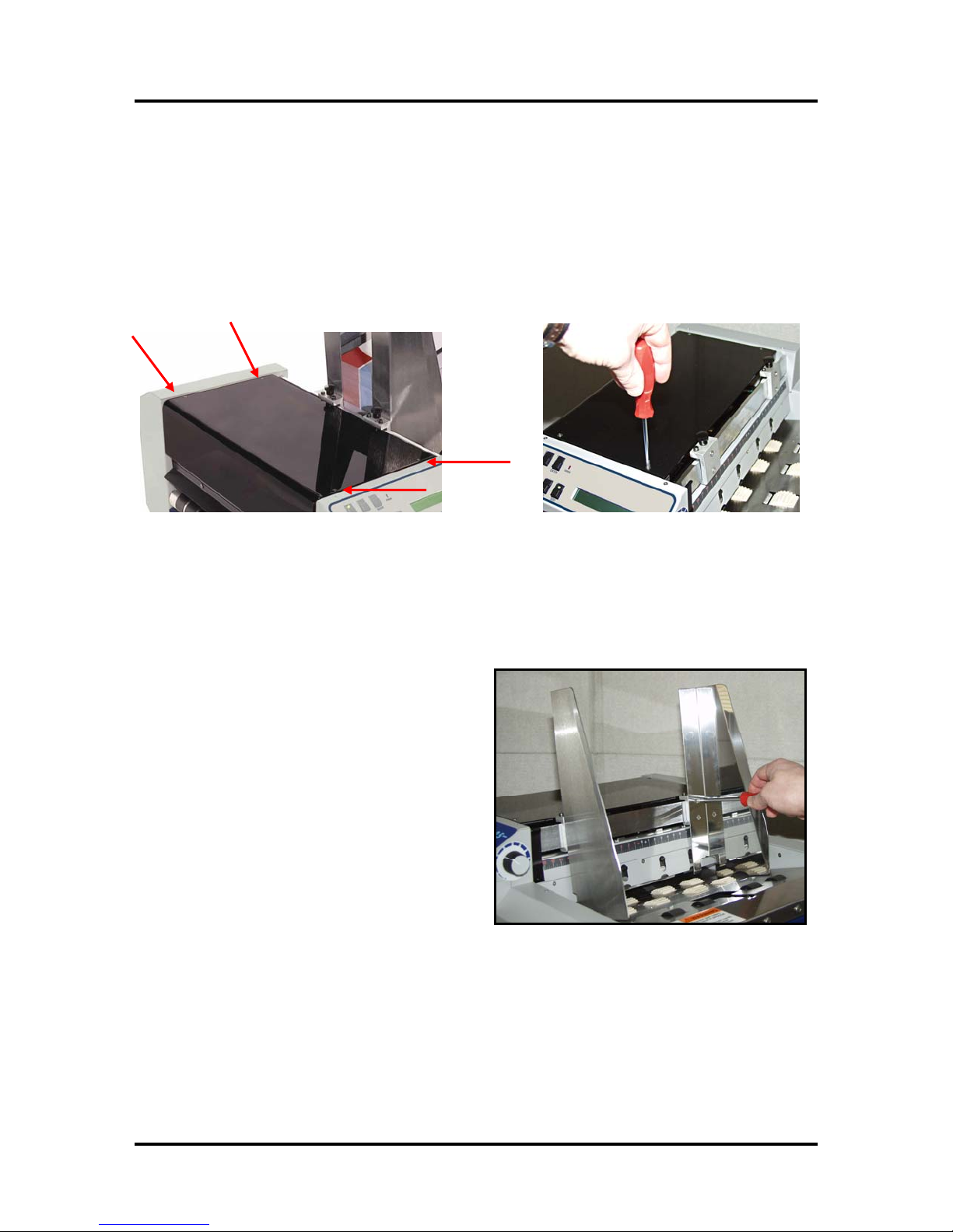
INITIAL ASSEMBLY___________________________________________________________________6
Attach the Print-Carriage Cover______________________________________________________6
Attach the Media Side Guides ________________________________________________________6
Attach the Rear Paper Support and Rear Media Guide ____________________________________7
SYSTEM REQUIREMENTS ______________________________________________________________7
OPERATOR VIEW ____________________________________________________________________8
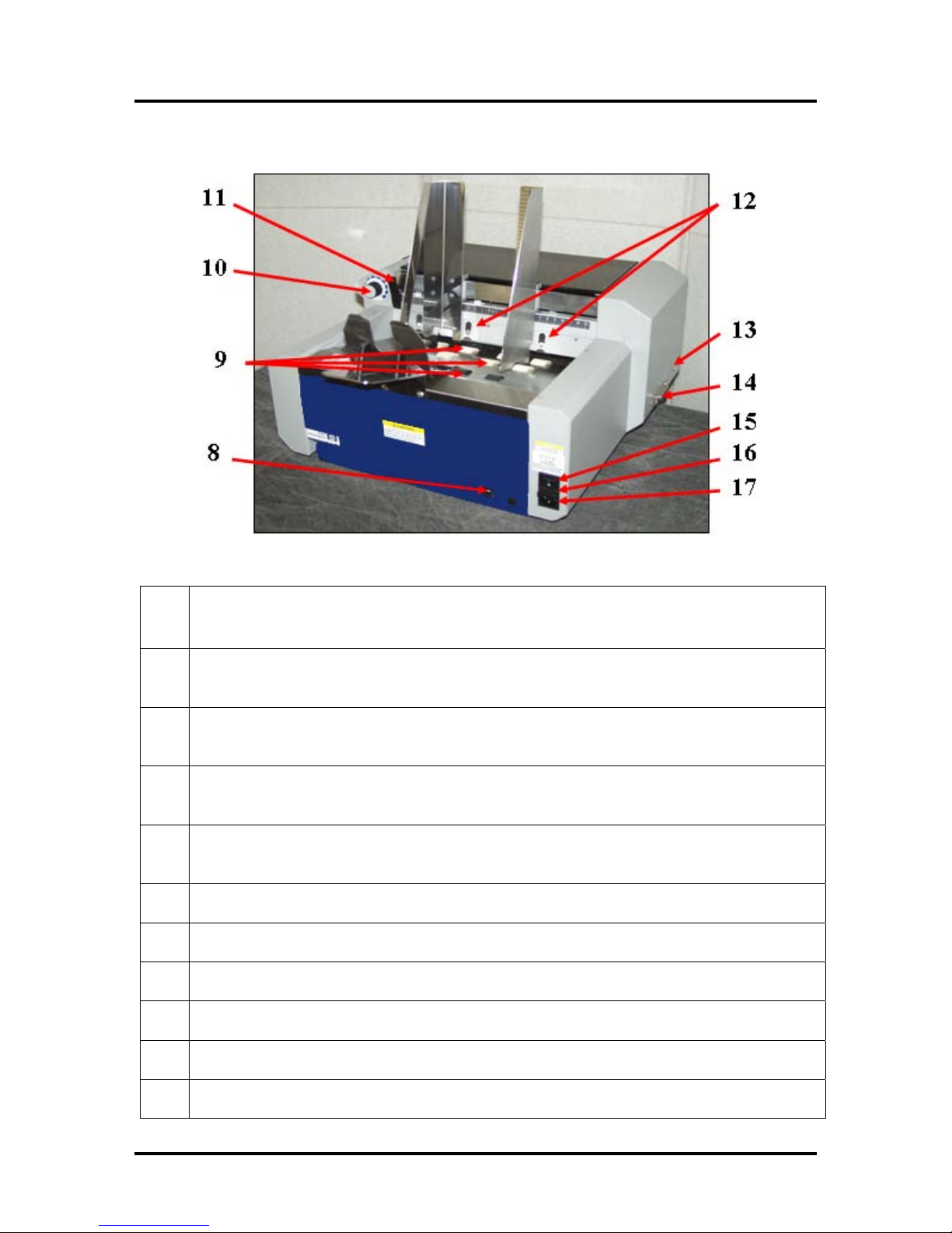
REAR VIEW ________________________________________________________________________9
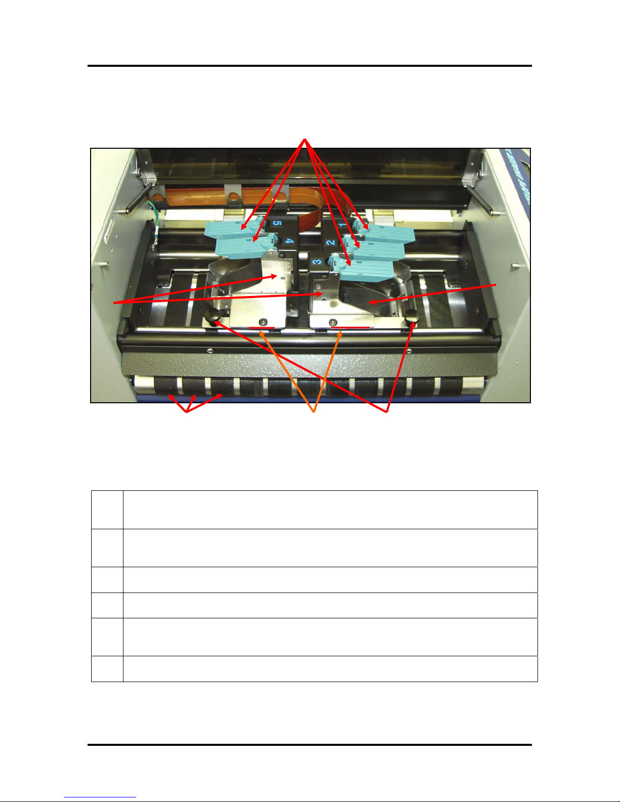
PRINT CARRIAGE VIEW ______________________________________________________________10
CONTROL PANEL ___________________________________________________________________ 11
SECTION 2 – PRINTER INSTALLATION AND SETUP __________________________________ 13
CHOOSE A LOCATION ________________________________________________________________ 13
CONNECTING POWER TO THE PRINTER ___________________________________________________ 13
CONNECTING TO THE COMPUTER _______________________________________________________ 13
INSTALLING THE INK CARTRIDGES______________________________________________________ 14
Ink Level Monitor Reset____________________________________________________________ 14
SETTING UP THE FEED SYSTEM ________________________________________________________ 15
Sheet Separation Adjustment________________________________________________________ 15
Media Side Guide Adjustments ______________________________________________________ 16
Rear Media Guide Adjustments______________________________________________________ 16
Loading Media___________________________________________________________________ 17
Media Thickness Adjustment________________________________________________________ 18
PRINT UNIT POSITIONING (VERTICAL ADDRESS POSITIONING) ________________________________ 19
PAPER FEED (MEDIA TRANSPORT)TEST _________________________________________________20
TEST PRINT _______________________________________________________________________20
SECTION 3 – OPERATING THE PRINTER ____________________________________________ 21
PRINTER CONTROL PANEL &MENU FEATURES ___________________________________________ 21
PRINT RECOVERY AFTER A JAM________________________________________________________ 23
INSTALLING THE PRINTER DRIVER ______________________________________________________24
USB Port Selection and Verification Process____________________________________________28
Printer Driver Properties______________________________________________________30
Print Heads Tab (Head Adjustment) __________________________________________________30
SOFTWARE SETUP EXAMPLES _________________________________________________________32
Printing from Satori Bulk Mailer® 5.0 ________________________________________________32
Printing from Microsoft Word_______________________________________________________34
SECTION 4 – MAINTENANCE _______________________________________________________ 37
INKJET CARTRIDGE MAINTENANCE _____________________________________________________ 37
Replacing the Inkjet Cartridge:______________________________________________________ 37
Inkjet Cartridge Storage ___________________________________________________________ 38
Cartridge Disposal _______________________________________________________________ 38
Cleaning the Inkjet Cartridge (Printhead) _____________________________________________ 38
Limitations of this document: The information presented herein is subject to change. 10/14/2009 Neopost USA Inc. assumes no liability whatsoever
for any losses or damages resulting from use of this information. © 2009 Neopost USA Inc. All rights reserved.
2
11/24/2009

Purging the Nozzles_______________________________________________________________ 37
JAMS IN THE PRINTER ________________________________________________________________ 37
Removing Jammed Media __________________________________________________________ 37
REPLACING THE SHEET SEPARATORS ____________________________________________________ 37
CLEANING THE PRINTER ______________________________________________________________40
Rubber Rollers ___________________________________________________________________40
Media Transport Belts _____________________________________________________________40
Cleaning the Media Sensor _________________________________________________________41
SECTION 5 – TROUBLESHOOTING GUIDE ___________________________________________43
HP INKJET PRINT CARTRIDGES ________________________________________________________43
THE PRINTER ______________________________________________________________________44
PRINTER DISPLAY MESSAGES _________________________________________________________45
APPENDIX A – AS-940 SPECIFICATIONS_____________________________________________ 47
APPENDIX B – SUPPLIES, SERVICE AND SUPPORT __________________________________ 48
INDEX ___________________________________________________________________________ 49
Limitations of this document: The information presented herein is subject to change. 10/14/2009 Neopost USA Inc. assumes no liability whatsoever
for any losses or damages resulting from use of this information. © 2009 Neopost USA Inc. All rights reserved.
3
11/24/2009

SECTION 1
GETTING ACQUAINTED
Section 1 – Getting Acquainted
Safety Precautions
THIS EQUIPMENT PRESENTS NO PROBLEM WHEN USED PROPERLY. HOWEVER,
CERTAIN SAFETY RULES SHOULD BE OBSERVED WHEN OPERATING THE PRINTER.
BEFORE USING THE PRINTER, YOU SHOULD READ THIS MANUAL CAREFULLY
AND FOLLOW THE RECOMMENDED PROCEDURES, SAFETY WARNINGS, AND
INSTRUCTIONS:
9Keep hands, hair, and clothing clear of rollers and other moving parts.
9Avoid touching moving parts or materials while the machine is in use. Before clearing a jam, be sure
machine mechanisms come to a stop.
9Always turn off the machine before making adjustments, cleaning the machine, or performing any
maintenance covered in this manual.
9Use the power cord supplied with the machine. Plug it into a properly grounded wall outlet located
near the machine and easily accessible. Failure to properly ground the machine can result in sever
personal injury and/or fire.
9The power cord and wall plug is the primary means of disconnecting the machine for the power
supply.
9DO NOT use an adapter plug on the line cord or wall outlet.
9DO NOT remove the ground pin from the line cord.
9DO NOT route the power cord over sharp edges or trapped between furniture.
9Avoid using wall outlets that are controlled by wall switches, or shared with other equipment.
9Make sure there is no strain on the power cord caused by jamming between the equipment, walls or
furniture.
9DO NOT remove covers. Covers enclose hazardous parts that should only be accessed by a qualified
service representative. Report any damage of covers to your service representative.
9This machine requires periodic maintenance. Contact your authorized service representative for
required service schedules.
9To prevent overheating, do not cover the vent openings.
9Use this equipment only for its intended purpose.
9Follow any specific occupational safety and health standards for your workplace or area.
Limitations of this document: The information presented herein is subject to change. 10/14/2009 Neopost USA Inc. assumes no liability whatsoever
for any losses or damages resulting from use of this information. © 2009 Neopost USA Inc. All rights reserved.
4
11/24/2009

SECTION 1
GETTING ACQUAINTED
Packaging/Shipping
The printer is shipped in appropriate packaging so that, under normal shipping conditions, it
reaches its destination without damage.
NOTICE: Report damage to the carrier. The carrier is liable for any damage during transport. Transport
and storage should take place under normal conditions, i.e. at temperatures between +5°C and +70°C and
relative air humidity of up to 80%. Exposure to conditions that are not permissible may lead to damage
which is not externally visible.
Please save the packaging for future use! It will be required if you ever need to ship the printer.
Contents
The following items are included with your printer:
1 Print-Carriage Cover (including mounting hardware)
1 Power Cord
2 Media Side Guides (mounting hardware attached to printer)
1 Rear Paper Support (mounting hardware attached to item and printer)
1 Rear Media Guide (attached to Rear Paper Support)
1 Product CD ((Operations Manual (PDF) and all necessary Drivers files included on this CD))
Note: Parallel and USB interface cables and Ink cartridges are not included with the printer.
Interface USB cables (recommend 6 ft or less) can be purchased from computer and office supply
stores.
Ink cartridges can be purchased through your local Neopost dealer or branch.
Figure 1
© 2009 Neopost USA Inc. All rights reserved.
5

SECTION 1
GETTING ACQUAINTED
Initial Assembly
Attach the Print-Carriage Cover
Using the 4 flat-head Philips screws supplied; attach the Print-Carriage Cover to the printer.
WARNING! Be careful not to over tighten the screws or you will damage the cover.
Attach the Media Side Guides
Using the 4 flat-head Philips screws supplied;
attach the Media Side Guides to the printer.
Note: The screws are shipped; attached to side
guide securing plates, on the printer.
Figure 2
© 2009 Neopost USA Inc. All rights reserved.
6

SECTION 1
GETTING ACQUAINTED
Attach the Rear Paper Support and Rear Media Guide
Note: The Rear Media Guide is shipped attached to the Rear Paper Support. The Rear Paper
Support mounting screws are shipped; attached to rear paper support and the printer.
Loosen the two large Rear Paper Support
securing screws (2 Philips head screws)
about 3 revolutions.
Positioned the upper portion, of the paper
support assembly, inside the table-top
cutout and then slide the lower portion of
the paper support behind the two
loosened screws.
Using the two small Philips head screws
supplied, attach the upper portion of the rear
paper support to the deck of the printer.
Secure the two lower Philips head screws.
System Requirements
•Pentium III-class PC (500 MHz or higher recommended)
•Windows 98, Windows NT 4.0 (Service Pack 6 or higher), Windows 2000,Windows
XP or Windows Vista (32 or 64 bit). You must have administrative privileges on the system.
•Microsoft Internet Explorer 5.0 or higher.
•System memory depending on your operating system.
•At least 120 Mb free hard-disk space.
•CD-ROM drive
•Centronics Parallel and or USB port
Figure 3
Figure 4
Figure 5
© 2009 Neopost USA Inc. All rights reserved.
7

SECTION 1
GETTING ACQUAINTED
Operator View
1. PRINT-CARRIAGE COVER – The Print-Carriage Cover encloses the printhead
carriage and media transport rollers/belts.
2. MEDIA SIDE GUIDE SECURING KNOBS – Used to secure the Media Guides
at their desired locations.
3. MEDIA SIDE GUIDES – Used to center the media in the printer and provide
straight feeding of media.
4. REAR PAPER SUPPORT – Provides the proper angle to enhance media feeding
and separation.
5. LCD DISPLAY – Displays information about the status of the printer.
6. PRINTER CONTROL PANEL – The keys on the printer control panel are used
to operate the printer.
Figure 6
1 2
3
4
5
6
© 2009 Neopost USA Inc. All rights reserved.
8

SECTION 1
GETTING ACQUAINTED
Rear View
7. REAR MEDIA GUIDE – Allows for adjustments in stack angle, based on media
type and length. Helps to force the media against the separation area.
8. MOTOR CIRCUIT BREAKER – The circuit breaker protects the printer’s motor from
overload.
9. FEED ROLLERS – (8 serrated, 4 black) Delivers the bottom piece of media, from the
stack, through the separation area, and under the forwarding rollers.
10. MEDIA THICKNESS ADJUSTMENT DIAL – Is used to set the printheads at the
proper height for printing on the media.
11. SHEET SEPARATOR LOCKING LEVER – Is used to lock the separators in place
after they are adjusted.
12. SHEET SEPARATORS – (four) Use to separate a single piece of media from the stack.
13. USB PORT – Connects the printer to the USB port on your computer.
14. PARALLEL PORT – Connects the printer to the parallel printer port on your computer.
15. MAIN POWER SWITCH – This switch turns the printer ON and OFF.
16. MAIN POWER FUSE – This fuse protects all of the electronic circuits in the printer.
17. POWER RECEPTACLE – The power cord is plugged in here.
Figure 7
© 2009 Neopost USA Inc. All rights reserved.
9

SECTION 1
GETTING ACQUAINTED
Print Carriage View
18. PRINT UNITS – One holds 3 ink cartridges (cartridges 1, 2, 3) and the other holds 2 ink
cartridges (cartridges 4, 5). Can be moved to adjust the vertical print position.
19. INK CARTRIDGE LATCH LEVERS – Used to secure the inkjet cartridge in to the
Pen Stall.
20. PEN STALL – The area where the inkjet cartridge is inserted.
21. PRINT UNIT SECURING KNOBS – Used to secure the print unit positions.
22. PRINT AREA REFERENCE – Visual reference to help the operator adjust print area
position.
23. MEDIA TRANSPORT BELTS – Drives the material through the system.
23
19
18
21
20
22
Figure 8
© 2009 Neopost USA Inc. All rights reserved.
10

SECTION 1
GETTING ACQUAINTED
Control Panel
1.
ON LINE key – This key is used to put the printer on/off line.
LED “slow flash” = Printer is powered on, but off-line.
LED “on” = Printer is on-line
Note: The printer must be off-line to access the menu modes or TEST print.
2. - key – In the menu mode this key will scroll to the previous selection.
3.
ENTER key – This key is used to start/stop media feed.
When the printer is placed in any of the menu modes, the ENTER key is used to select the
options available.
When the printer is off-line this key is used to start the Paper Feed function.
4. ERROR Indicator – This indicator lights when there is a problem with the printing process.
5. RESET key – Holding down this key, until all LED’s light momentarily, will reset the printer
to its normal ready state.
6. + key –In the menu mode this key will scroll to the next selection.
7. MENU key – This key causes the printer to enter the menu mode where several operator
functions can be accessed.
8. TEST key – Pressing this key will put the printer into the test pint mode (LED on); allowing the
printer’s internal “test image” to be printed.
9. LCD DISPLAY – Indicates the status of the printer including piece count, menus, and error
messages.
10. MEDIA THICKNESS ADJUSTMENT DIAL– The dial on the right side of the control panel
is used to adjust the height of the print heads to compensate for different media thickness.
NOTE: A complete description of the functions and operation of the printer keys
can be found in Section 3 – Operating the Printer.
Figure 9
© 2009 Neopost USA Inc. All rights reserved.
11

SECTION 1
GETTING ACQUAINTED
Notes
© 2009 Neopost USA Inc. All rights reserved.
12

SECTION 2
INSTALLATION & SETUP
Section 2 – Printer Installation and Setup
Before using the printer, the following must be done:
•Choose a location for the printer
•Connect power to the printer
•Connect it to the computer
•Install the Inkjet Cartridges
•Set up the feed system (media separation and transport) on the printer
•Position the Print Units
Choose a Location
The printer should be placed on a sturdy worktable or cabinet at least 12 inches from any walls.
Protect the printer from excessive heat, dust, and moisture – avoid placing it in direct sunlight.
Connecting Power to the Printer
1. Make sure that the main power switch of the Printer is in the
OFF (0) position.
2. Verify that the power source is the correct voltage for your
printer, and it is properly earth grounded. The use of a surge
protector is recommended.
3. Connect one end of the power cord to the rear of the Printer in
the corresponding receptacle.
4. Plug the other end into a 115 Volt AC, 50/60 Hz. Grounded
outlet.
CAUTION
Do not use an adapter plug or extension cord to connect the
printer to the wall receptacle. Figure 10
Do not use outlets controlled by wall switches.
Do not use an outlet that shares the same circuit with large electrical machines or appliances.
Surge Protectors are recommended.
Connecting to the Computer
USB Users: Plug the USB cable from your
computer, into the printer’s USP USB Port,
located next to the parallel port connector.
Parallel Users: Plug the parallel printer
cable from your computer into the printer’s
Parallel Port and latch the two locking
clips. Figure 11
NOTE: The cable used to connect the printer to the computer must not exceed 6 feet long. The parallel
port may be used for all versions of Windows. The USB Port is used only for Windows ME, 2000,
and XP.
© 2009 Neopost USA Inc. All rights reserved.
13

SECTION 2
INSTALLATION & SETUP
Installing the Ink Cartridges
The printer can accommodate 5 HP45A style inkjet cartridges. The cartridges are installed as follows:
Remove the inkjet cartridge from its packaging,
taking care not to touch the copper contacts or the
nozzle plate. Remove the protective tape from the
inkjet cartridge.
See “Appendix B” for a list of ink cartridges that are
available for your printer.
•The cartridges are held in place by a latch lever
mounted on the inkjet cartridge holder (pen stall).
Release the lever by raising it vertical.
•With the cartridge’s nozzle plate pointing down, slide
the cartridge into the pen stall and push down and
toward the contacts in the pen stall.
•Make sure the cartridge is seated in the pen stall then
close the latch lever to secure the cartridge in the pen
stall. Do not force the lever into place. (See the
diagram.)
•Reset the ink level monitor for this cartridge.
See “Ink Level Monitor Reset” below.
•Repeat the above for the remaining cartridges.
Ink Level Monitor Reset
The printer can automatically calculate the approximate ink level available in each cartridge. It does
this using a drop count method. When the level is calculated as being low (~5% ink remaining in the
cartridge) the printer will stop and display “Head # Low. Press Enter.”. After you press Enter, you
can choose to ignore the warning or you can check the cartridge. If the cartridge is almost empty, you
should replace the cartridge and reset the Ink Level Monitor using the flowing procedure.
Press the MENU key momentarily.
Use the “+” or “-” key to highlight “Enter when head (n) is filled”.
Press the ENTER key and install a new cartridge.
Repeat for each cartridge you install. When the ENTER key is pressed the display will change to
“Head (n) has a new cartridge”.
NOTE: This feature is only valid if the cartridges remain in their original positions, where they were
first installed. If you swap the cartridges from one stall position to another, the calculated ink levels
will not be accurate. It is suggested that you tag the cartridges with their original position number.
Quick Ink Level Monitor Reset (all Heads):Power the printer on while holding down the MENU key,
until the printer displays “Resetting all Ink Levels in Flash”. Then release the MENU key.
To check the level of ink in the cartridges, Press and hold the TEST key until the “Service Menu”
appears. Use the “+” or “-” key to scroll to the “Service Menu: Ink Levels, 100%100%100%”. This
will show how much ink remains in the cartridge.
The ink in the cartridge may be harmful if swallowed. Keep new and used
cartridges out of reach of children. Discard empty cartridges immediately.
Figure 12
Figure 13
© 2009 Neopost USA Inc. All rights reserved.
14

SECTION 2
INSTALLATION & SETUP
Setting up the Feed System
The printer is equipped with four sheet separators, two media side guides, a rear media guide, and a media
thickness adjustment dial.
Sheet Separation Adjustment
The sheet separators are adjusted individually as follows:
1. Move the side guides so that the separators and
separator locking lever are accessible.
2. Release the Separator Locking Lever, by pulling it
forward and down, as shown in .
Figure 15
3. Lift each individual separator up, until it locks in
the upper position, as shown in .
Figure 16
4. Place a single piece of media under the separators,
as shown in .
It is best to place the media so it is in the center
position on the table.
Figure 17
5. Unlock the separators that have media beneath
them and allow them to fall (by their own weight)
onto the media, as shown in .
Repeat for each separator that has media under it.
IMPORTANT
Be sure that unused separators are locked in their
raised position. If not, they will rub on the feed
rollers, causing transport problems and damage to
the rollers and separators.
Figure 18
6. Raise the Separator Locking Lever, by lifting it up
and back, as shown in . This will lock
the separator positions.
Figure 19
Figure 14
Figure
16
Figure 17
Figure 18
Figure 15
© 2009 Neopost USA Inc. All rights reserved.
15

SECTION 2
INSTALLATION & SETUP
Media Side Guide Adjustments
Figure 19
1. Loosen the Media Side Guide Securing Knobs, as
shown in .Figure 20
2. Move the side guides apart, so the media will fit
between them and be centered in the feed area.
3. If not already present; place one piece of media
between the side guides, so the media is centered in
the feed area.
4. Adjust the Media Side Guides so that they are about
a dimes width (~1/32-inch) from the sides of the
media, as shown in .
Figure 21
5. Tighten the Media Side Guide Securing Knobs, to
secure the side guide positions.
Figure 20
Rear Media Guide Adjustments
1. Place two pieces of media into the hopper, making sure the leading edges of the media is resting
against the separators.
2. Adjust the Rear Media Guide position by sliding it up or down on the Rear Media Support.
Position it so that the trailing edge of the media is raised approximately ½ to 1 inch above the Rear
Media Support, as shown in .Figure 22
Figure 21
0.5” – 1”
GAP
© 2009 Neopost USA Inc. All rights reserved.
16

SECTION 2
INSTALLATION & SETUP
Loading Media
When placing media into the printer, it is important to follow these steps.
1. Start by placing a single piece of media into the feed
section, so that it is touching or starting to feed under
the sheet separators.
2. Before adding media; fan the stack of material so the
bottom pieces are closest to the separation point, as
shown in . Then carefully place the stack
between the side guides, so the leading edge of the
stack is against the sheet separators, as shown in
.
Figure 23
Figure 24
3. Additional pieces can be placed onto the stack, as
described in the above step.
4. If the printer runs out of material, be sure to reload
the printer beginning with the first step.
Figure 22
Fi
g
ure 23
© 2009 Neopost USA Inc. All rights reserved.
17

SECTION 2
INSTALLATION & SETUP
Media Thickness Adjustment
The printhead carriage height must be set to accommodate the thickness of the media you will be
feeding. This printer incorporates a servo motor to control the height of the carriage.
1. Make sure the printer is off-line. If on-line, press the ONLINE key to take it off-line.
2. Press the MENU key, then use the +key to scroll to the menu item “Media Thickness Setup”. Press
the ENTER key to select this feature.
3. Turn the Media Thickness Dial [A] fully
clockwise. This will cause the servo motor
to raise the printhead carriage to its highest
position.
4. Place a piece of media [B] under the
printhead carriage rollers, as shown in
.Figure 25
5. Slowly adjust the Media Thickness Dial [A]
counter-clockwise until the printhead
carriage rollers touch and hold the Media
[B] securely. Figure 24
6. When properly adjusted the Media [B] will
be securely captured between the printhead
carriage rollers and the lower transport
belts. It should require a moderate amount
of force to pull the Media [B] from under
the printhead carriage rollers.
Tip: Make a note of the Media Thickness
Dial position, as a reference for future
adjustment when using this particular
media.
7. Press the MENU button to exit out of the
“Media Thickness Setup” mode.
NOTE: The printer will automatically raise the printhead carriage to its highest position, when you exit
the “Media Thickness Setup” mode. When the printer is told to print or feed material, it will
automatically lower the carriage to your preset value.
The chart below can be used as a general guideline for setting the position of the Media
Thickness Dial [A].
Media Thickness Dial Setting
.004” to 1/32” 0 to 2
1/32” to 1/16” 2 to 3
1/16” to 1/8” 3 to 7
1/8” to 1/4” 7 to 10
NOTE: The chart show general guidelines. It is best to adjust the carriage height using the
procedure outlined above.
© 2009 Neopost USA Inc. All rights reserved.
18

SECTION 2
INSTALLATION & SETUP
Figure 26
Figure 27
Figure 27
Print Unit Positioning (Vertical Address Positioning)
The print units are the device that contains the pen stalls and inkjet cartridges. To adjust the vertical
position of the address (printed image) on the media, you must move the Print Units to the desired print
positions. The red lines, at the exit end of the print unit, can be used to approximate the print position on
the media, as shown in Figure 27.
1. Loosen the Print Unit Securing Knobs. See .
2. Slide the Print Units to the desired positions as shown in .
3. Tighten the Print Unit Securing Knob.
Note: Horizontal print position is adjusted via your software (mailing program).
Figure 27
Note: The minimum gap (distance) between the print units (between heads 3 and 4) is 1 5/16”.
PRINT
AREA
3, 2, 15, 4
No. 10 Envelope
© 2009 Neopost USA Inc. All rights reserved.
19

SECTION 2
INSTALLATION & SETUP
Minimum Distance Between Print Units (Heads 3 & 4)
Figure 28 shows the minimum distance between print units.
This minimum is achieved by pushing the print unts against one another.
Figure 28
Paper Feed (Media Transport) Test
Test for proper media transport.
If the printer is setup properly, it should feed the media without hesitation, skewing or jamming.
1. With the printer off-line, press the ENTER key, to start the Paper Feed feature (feeds material
without printing).
2. Press ENTER again to stop the Paper Feed feature.
TEST Print
When off-line, the TEST key can be used to print a TEST image.
The TEST image can be used to:
Check the vertical print position.
Demonstrate the printer.
Check the condition or the ink cartridges.
Check the function of the printer.
Note: Horizontal print position is adjusted via your software (mailing program).
Customizing the TEST Print Image:
The TEST print image can be changed to any image you desire, by using the following
procedure:
1. Power the printer on while holding down the TEST key.
2. From your computer; send an image that you would like to be the new TEST image.
Note: Turning the printer on, while holding down the TEST key, will erase the previous TEST image. If a
new TEST image is not loaded, then a TEST image will not be available to print when you press the TEST
key.
© 2009 Neopost USA Inc. All rights reserved.
20
Table of contents
Other Neopost Postal Equipment manuals

Neopost
Neopost IS-200 Series User manual

Neopost
Neopost IJ65 User manual

Neopost
Neopost IS-5000 User manual

Neopost
Neopost Automailer 5 User manual

Neopost
Neopost IJ 70 User manual

Neopost
Neopost ij25 User manual

Neopost
Neopost IM-18 User manual

Neopost
Neopost 5050 User manual

Neopost
Neopost IS-280 iMeter User manual

Neopost
Neopost IJ-60 User manual

Neopost
Neopost IJ35 User manual

Neopost
Neopost IS-6000 User manual

Neopost
Neopost CS-200 User manual

Neopost
Neopost IM-19 User manual

Neopost
Neopost ij25 User manual

Neopost
Neopost IN-600 Series User manual

Neopost
Neopost IM-15 User manual

Neopost
Neopost IS-5000 User manual

Neopost
Neopost 3063 User manual

Neopost
Neopost IJ-50 User manual