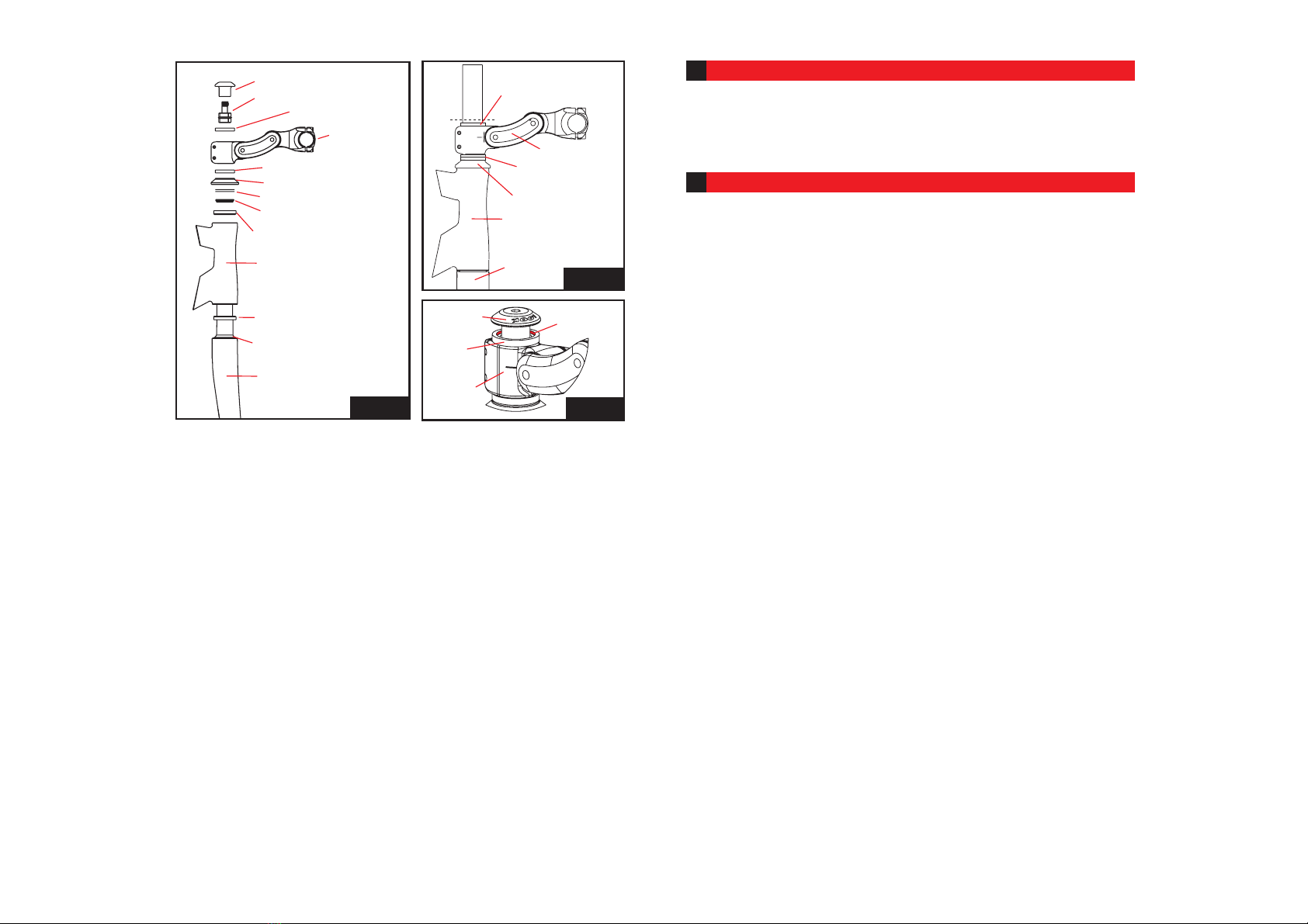
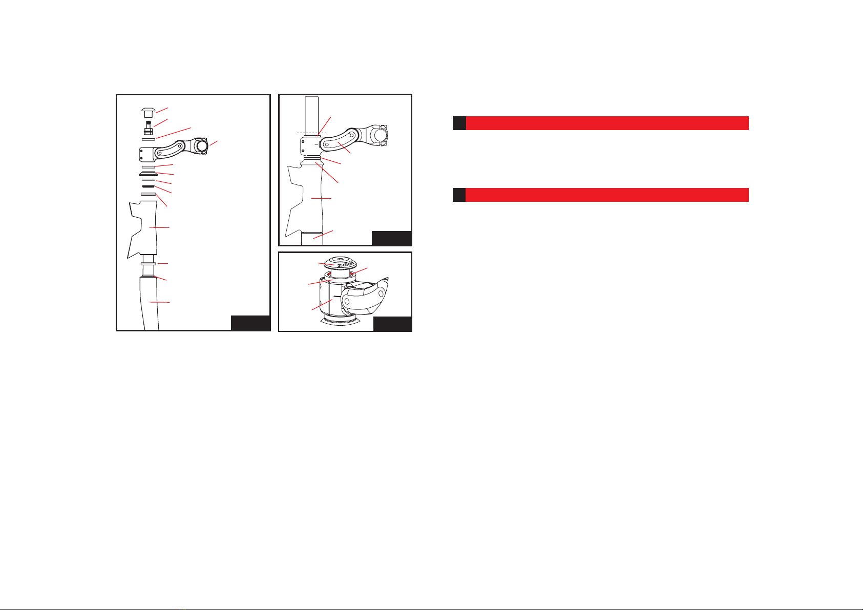
Anillo específico
Montante
Spacers
(anillo de esperor)
Capuchón
Casquillo de direc-
ción del bastidor
Horquilla
dirección.
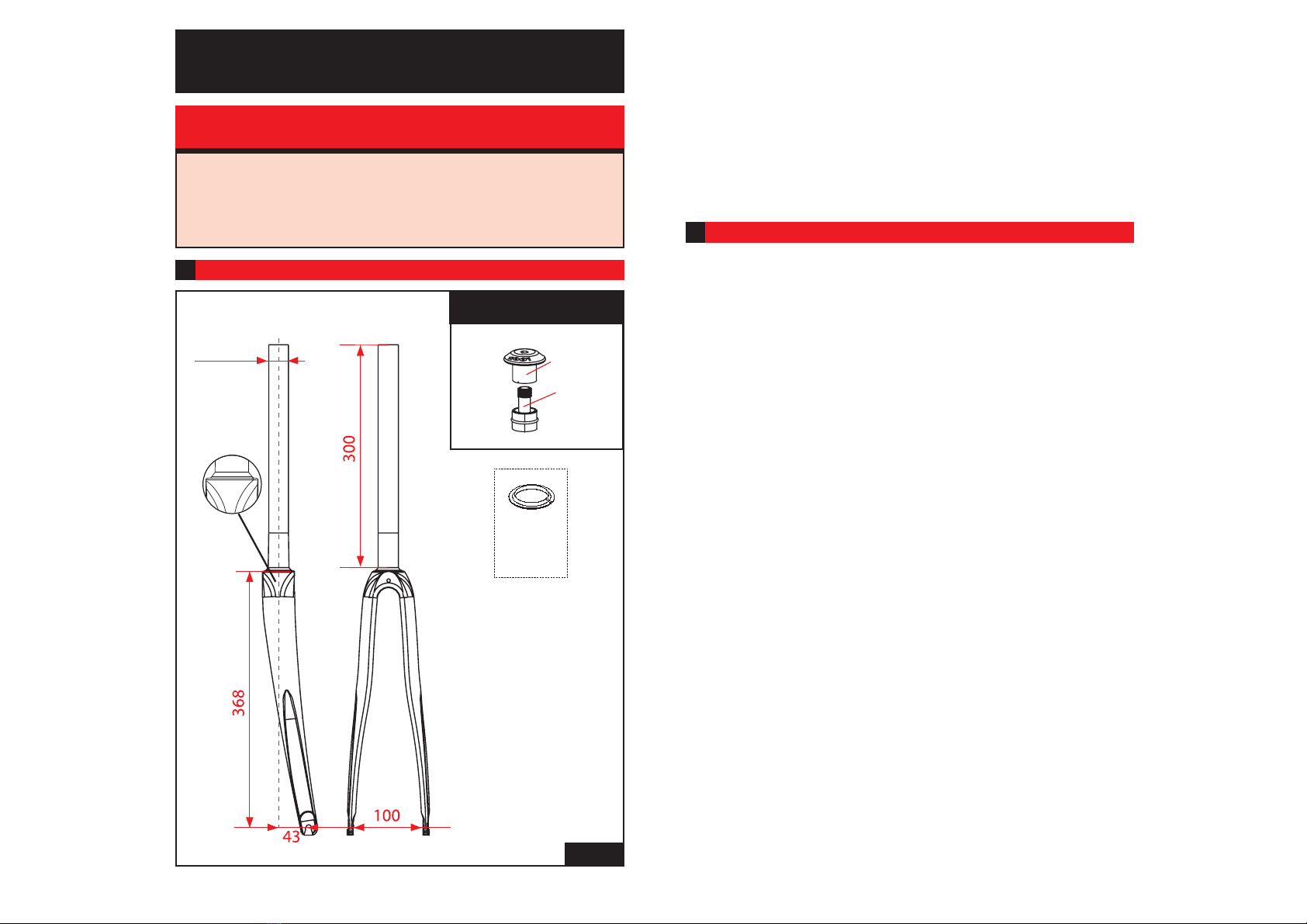
10 - Añada los anillos necesarios y marque el tubo pivote.
11 - Desmonte todo para cortar el pivote de la horquilla, 1 a 2mm debajo del lugar refe
renciado. Le recomendamos utilizar un corta tubo o una sierra de metales.
(ver Fig. c)
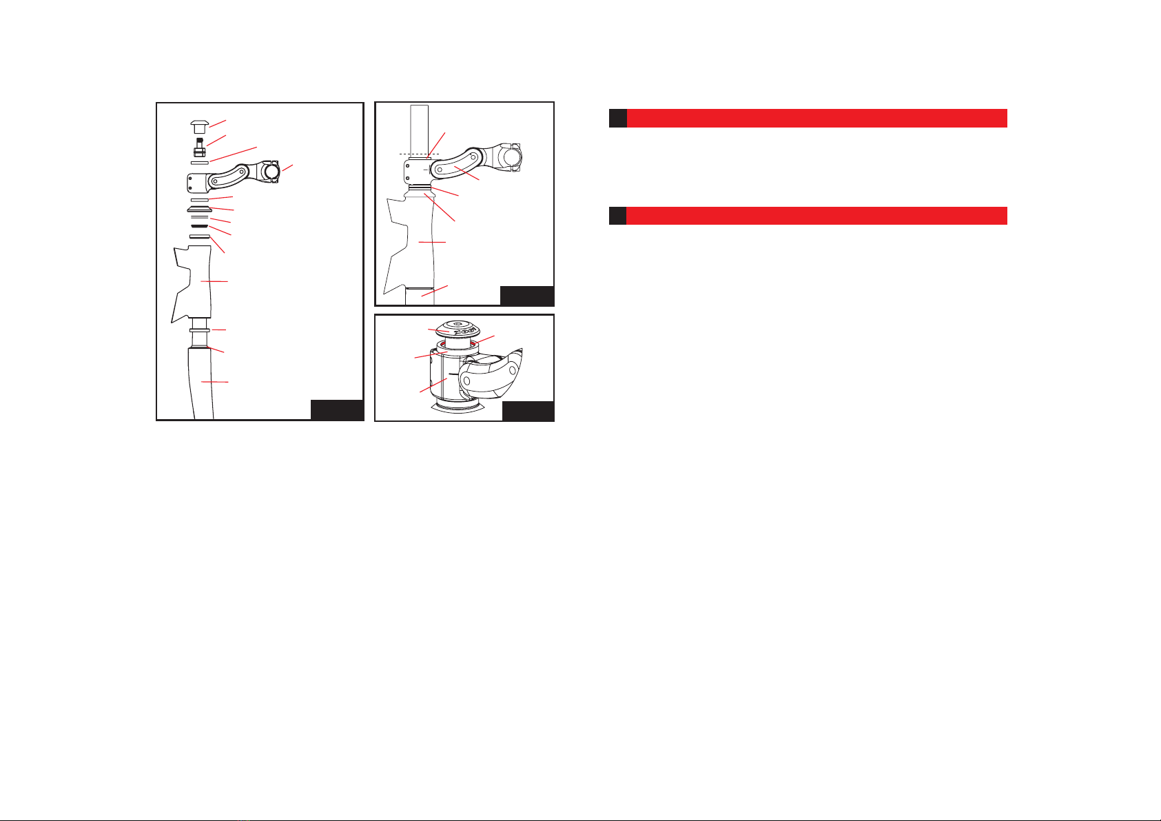
Tapón de compresión
Extensor
Anillo específico
Montante (8)
Spacer (anillo de espesor) (7)
Capuchón (6)
Anillo hendido cónico (4)
Rodamiento superior Ø41 (3)
Direccion del cuadro (2)
Rodamiento inferior Ø41 (1)
Collarín cónico 36° de la hor-
quilla
Horquilla
Fig. b
Riostras de espesor (5)
ATENCIÓN: El carbono es un material muy abrasivo que deteriora rápidamente las her-
ramientas. Si el tubo pivote es demasiado largo, la compresión del juego de dirección
será insuficiente. El resultado será un deterioro rápido del juego de dirección. Si el
tubo es demasiado corto, la superficie de contacto entre el tubo pivote y el montante
será demasiado débil y el aguante del montante no será óptimo. No utilice nunca un
tubo pivote fileteado con un juego de dirección pivote.
ATENCIÓN: Utilice el tapón suministrado con la horquilla. Un tapón mal adap-
tado puede deteriorar el pivote de horquilla y provocar un grave accidente.
• Volver a apretar los tornillos del montante al par máx. de 10 Nm.
IMPORTANTE: No engrasar el tubo pivote. No apretar el montante sin el tapón
de ajuste montado. Utilice el kit de compresión LOOK suministrado con la hor-
quilla u otro kit adaptado a un pivote carbono pues el interior del kit de com-
presión tiene una función: sirve para reforzar el interior del pivote para que
éste resista al aplastamiento. Utilice solamente montantes con una superficie
de apriete superior a 1cm2. Evitar absolutamente todos los aprietes efectuados
con tornillo punzón así como todos los sistemas de grapas.
• Vuelva a montar el conjunto según el esquema de montaje de la Fig. b
• Atornille algunas vueltas el tapón de compresión sobre el extensor
• Inserte el kit de compresión en el tubo pivote de la horquilla.
• Apriete el tornillo BTR5 del extensor pasando por el agujero del tornillo del tapón de
compresión, con ayuda de una llave ALLEN n°6 (ver “Instrucciones kit de compresión”)
con el fin de asentar el juego de dirección hasta que no sea perceptible ningún juego
en la dirección.
*Para “notar” el juego, apriete el freno delantero y accione suavemente la rueda delan-
tera, de delante hacia atrás. Notará fácilmente el juego en su mano posicionada sobre
el manillar y apretando el freno delantero.
*Atención si el capuchón del kit de compresión toca el tubo pivote, el juego no se
puede ajustar. Hay que dejar siempre 1 a 2 mm entre el vértice del último anillo y el
tubo pivote de la horquilla para permitir al capuchón jugar su papel de compresión del
juego de dirección. (ver Fig. d)
Tapón de
compresión
Anillo
específico
1-2mm
Montante
Fig. d
Fig. c
MANTENIMIENTO DE LA HORQUILLA
3
Utilizar un trapo suave y un detergente ligero con un poco de agua para limpiar la
horquilla, secarla completamente después del lavado o de su utilización en condicio-
nes climáticas húmedas. ATENCIÓN: no utilizar productos abrasivos, disolventes o
chorro de agua de alta presión para limpiar la horquilla, esto anularía la garantía
LOOK.
GARANTÍA
4
Nuestras horquillas están garantizadas durante 5 años a partir de la fecha de com-
pra contra cualquier vicio o defecto de fabricación. La pintura, las transferencias, el
barniz y todo lo relativo al acabado están garantizados durante 1año.
Para que la garantía sea válida, la hoja adjunta debe imprescindiblemente ser relle-
nada por el vendedor y devuelta debidamente franqueada a LOOK CYCLE INTER-
NATIONAL, el único habilitado para validar el aviso de garantía. Esta garantía no es
transferible a ningún otro y se requiera la correspondiente prueba de compra (factura
original).
La garantía se refiere a las horquillas para cualesquiera vicios o defectos de fabrica-
ción.
La garantía se aplica únicamente si la horquilla se monta conforme a las instruccio-
nes más arriba.
La garantía no se aplica a los defectos debidos a un mantenimiento incorrecto o a
una mala utilización.
Asimismo, la garantía caduca si ha sufrido una modificación técnica por el usuario o
si el producto ha sido reparado o repintado fuera de un centro de reparación autori-
zado LOOK.
Cualquier modificación del producto anula la garantía. (Supresión de los espárragos
de seguridad o taladrado del carbono).
La garantía no cubre los casos siguientes:
• Los defectos causados por negligencia o mantenimiento insuficiente
• Los accidentes
• Los daños accesorios e indirectos
Los gastos de montaje, desmontaje, tiempo de mano de obra, embalaje y expedición
del bastidor no están cubiertos.
No agujerear, pintar o volver a barnizar.
No dejar la horquilla cerca de una fuente de calor.
ATENCIÓN: Inspeccione siempre su bicicleta antes de utilizarla. Si los tubos del bas-
tidor LOOK o la horquilla han sufrido algún daño, lleve la bicicleta a su vendedor
LOOK para una inspección. Respete el código de la circulación. Esté atente a los
avatares de la carretera. Lleve siempre un casco.
18 19