SATA AE5831 User manual

透明度拼合
AE5831
20 吨压机
Operating Instruction for 20t Press
20 Tonnen Presse
Пресс 20 т
20 톤프레스
Máquina de prensagem de 20 toneladas
20t(トン)プレス機械
Prensa de 20 toneladas
使用说明书 \ User’s Manual \ Bedienungsanleitung \ Инструкция по эксплуатации
사용설명서 \ Manual de instruções \ 取扱説明書 \ Manual del uso
中文 EN DE RU KO PT JA ES
AE5831八国-200620.indd 1AE5831八国-200620.indd 1 2020/6/23 19:26:442020/6/23 19:26:44

透明度拼合
透明度拼合
AE5831八国-200620.indd 2AE5831八国-200620.indd 2 2020/6/23 19:26:442020/6/23 19:26:44

3
透明度拼合
透明度拼合
开箱后即请检查产品,确保产品完好无损。如果发现有任何部件缺失或损坏,请电话联系世达工具(上海)有限公司客户服
务部:400-820-3885、800- 820-3885
请记录产品序列号:________
注:如果产品没有序列号,请记录购买日期。
请妥善保存本使用说明书:
1. 本使用说明书涉及产品的安全警告、安装操作、维护保养、常见故障处理等内容,请妥善保管。
2. 请记录本产品的序列号(或购买日期)在使用说明书首页,并将说明书保存于干燥安全之处以备参阅。
3. 请在完全理解本说明书内容的基础上,正确使用产品。
4. 本设备已经投保产品责任险。
安全警告:
1.使用前请务必仔细阅读并理解说明书的全部内容。不正确的操作可能导致人员损伤及产品损坏。
2.每次使用前都要仔细检查,如有漏油、零部件、附件松动或者损坏,都不能使用。
3.严禁超载使用本设备,否则引起的事故责任不在保险范围之列。
4.不能自行调节安全阀,否则引起的事故责任不在保险范围之列。
5.请保证儿童与其他未经许可的人员远离工作区域。
6.在挤压工件前,先缓慢施压确保可靠接触,再施力加压。
7.如果发现或者判断可能发生永久变形,请立即停止使用。
8.请在平整,水平,干燥并能可靠承载的平面上使用本设备。
9.本设备上使用的都是高强度螺栓,如需更换请选用原厂配件。
10.请选择正确的加压附件,如顶头、垫块、套筒,安全承载工件。
11.请勿将本产品暴露在雨水中,或任何不良天气状况下在室外使用。
12.请保持远离热源与火源,高温可能对本设备和密封元件造成损坏。
13.严禁任何未经培训的人员使用本设备,且不得自行拆装或改装本设备。
14.请让具有专业维修资质的专业人员合理维护设备,如需更换配件请使用原厂配件。
15.在操作时必须穿戴符合国家相关安全规定的安全鞋、防护眼镜和工作手套,推荐选用世达相关产品。
16.严禁在酒后、精神乏力、注意力不集中,受药物影响而困倦以及任何意识不清醒的情况下使用本产品。
警告:本手册中所包含的注意、警告、指示等信息不能涵盖所有可能发生的情况。
操作人员必须明白日常谨慎操作和具备专业知识是在操作本产品时不可或缺的因素。
产品编号 AE5831
品名 20 吨压机
额定重量(KG)20000
顶头 - 工作面
最高高度(MM)1010
±5
顶头 - 工作面
最低高度(MM)49
油缸移动距离(MM)397
活塞杆行程(MM)185
净重(KG)94.5
毛重(KG)98
外箱尺寸(CM)1# 155×19×14
2# 73×26×17
20 吨压机使用说明:
ESPT JARUEN DE KO
中文
AE5831
AE5831八国-200620.indd 3AE5831八国-200620.indd 3 2020/6/23 19:26:442020/6/23 19:26:44

4
透明度拼合
产品外形尺寸:
ESPT JARUEN DE KO
中文
AE5831
AE5831八国-200620.indd 4AE5831八国-200620.indd 4 2020/6/23 19:26:442020/6/23 19:26:44

5
透明度拼合
ESPT JARUEN DE KO
中文
AE5831
安装及操作:
安装步骤:
1.用 2 颗M12 螺栓固定一侧底脚、立柱与工形杆,其中立柱开口方向朝工形杆一侧。
2.用4颗M10螺栓,将斜撑板两端固定在底角与立柱上。
3.重复步骤1-2,将另一侧底脚、立柱、工形杆连接并固定。
4.用4颗M16螺栓将上梁后片固定在两根立柱顶端,将油缸板C形卡槽,卡入上梁后片槽板。
5.将上梁前片槽板插入油缸板C形卡槽内,并用 4颗M16螺栓将上梁前片与两根立柱固定。
6.下拼帽拆下后,将油缸装入油缸板组件,再将下拼帽装回并用C形扳手锁紧。
7.用24mm和27mm扳手逆时针将压力表堵头拆除后,用27mm 和 17mm 扳手将压力表安装在油缸顶部并拧紧。
8.用4颗M10螺栓将油泵组件安装在右侧立柱的机架上。
9.将油泵踏脚固定在立柱机架上,用开口销将踏脚连杆与油泵连接。
10.用4颗M10长螺栓及4根套管,完成下梁组装。
11.将2根插销插入立柱孔内,用挡圈固定后,放入下梁。
12.使用前请拧松加油排气螺母,拧松即可。
第一次使用前:
1.在第一次使用本设备前,需先排除液压系统的空气:顺时针关闭泄压阀,手动打泵将活塞杆完全顶出再旋松泄压阀,活塞杆自动收回,
待完全收回,排气完成。
操作说明:
1.旋紧泄压阀(顺时针),手动打泵,活塞杆工作。
2.旋松泄压阀(逆时针),活塞杆自动缩回。
3.可以根据工件位置滑动油缸板到合适位置,移动后请确保油缸板安装到位无倾斜现象。
排气说明 :
1.本设备在正常使用时,空气会随油路自动排出,无须手动排气。
维护保养 :
1. 使用完毕后,请确保旋松回油阀将顶杆恢复原位。
2. 定期检查柱活塞杆是否有生锈腐蚀情况,清洁后涂抹适量润滑油。
3.建议由专业技术人员进行年度检验。
换油说明:
1.为了保障产品的最好性能和使用寿命,请一年内至少一次彻底更换液压油。
油位检查:
1.将活塞杆完全伸出,继续踩下油泵踏板。油量充足时,油泵踏板需大力才可踩下。油量缺少时,稍用力,踏板即可压下。
补油步骤:
1.取下油泵上的堵头螺钉,注入适当的高质量液压油(加注到液面离上口2CM即可),然后装回堵头螺钉,请参照第一次使用前的方
法排出液压系统内的空气。
换油步骤:
1.活塞杆恢复原位(缩回初始位置)。
2.拆卸靠近液压表的油管接头,卸下油泵固定螺栓,卸下油泵部件。
3.将油泵上的堵头螺钉取下,翻转泵体,将液压油释放在合适的容器内。
4.注入适当的高质量液压油(替换的液压油最多不超过0.95升),然后装回堵头螺钉。
5.装回油泵部件,拧紧接头,连接油管。
6.请参照第一次使用前的方法排出液压系统内的空气。
注意:请按照当地的规定处理废弃的液压油
AE5831八国-200620.indd 5AE5831八国-200620.indd 5 2020/6/23 19:26:452020/6/23 19:26:45

6
透明度拼合
零件分解图及清单
PT JARUEN DE KO
中文
AE5831
图号 世达编号 配件品名 使用数量
1
PAE5822-1
防尘圈 1
2
PAE5822-2
O 形圈 1
3
PAE5822-3
进口 U 型圈 1
4
PAE5822-4
二级拼帽 1
5
PAE5822-5
O 形圈 1
ES
AE5831八国-200620.indd 6AE5831八国-200620.indd 6 2020/6/23 19:26:452020/6/23 19:26:45

7
透明度拼合
6
PAE5822-6
二级活塞杆 1
7
PAE5822-7
钢丝挡圈 1
8
PAE5822-8
防尘圈 1
9
PAE5822-9
O 形圈 1
10
PAE5822-10
进口 U 型圈 1
11
PAE5822-11
一级拼帽 1
12
PAE5822-12
O 形圈 1
13 PAE5822-13 一级活塞杆 1
14 PAE5822-14 限位钢丝挡圈 1
15 PAE5822-15 闷盖 1
16 PAE5822-16 内六角平端紧定螺钉 1
17 PAE5822-17 钢球 1
18 PAE5822-18 O 形圈 1
19 PAE5822-19 拼帽座 1
20 PAE5822-20 储油桶垫 2
21 PAE5822-21 储油桶组件 1
22 PAE5821-17 销轴 1
23 PAE5821-18 开口销 3
24 PAE5822-22 拉手 1
25 PAE5861-137 把手套 1
26 PAE5821-15 加油排气螺钉 1
27 PAE5821-14 组合密封垫 1
28 PAE5822-23 油缸 1
29 PAE5822-24 油缸垫 1
30 PAE5822-25 泵体部件 1
31 PAE5822-26 U 型限位 2 1
32 PAE5822-27 弹垫 1
33 PAE5822-28 内六角平圆头螺钉 1
34 PAE5822-29 放油踏脚 1
35 PAE5822-30 销轴 1
36 PAE5822-31 开口销 1
37 PAE5822-32 平垫 2
38 PAE5822-33 泵油脚踏组件 1
39 PAE5821-25 轴用挡圈 4
40 PAE5822-34 连杆 2
41 PAE5822-35 运送器连杆销 2
42 PAE5822-36 泵油连杆销 1
43 PAE5822-37 底脚组件 2
44 PAE5821-5 盖形螺母 4
45 PAE5821-6 弹垫 4
46 PAE5821-7 平垫 4
47 PAE5822-38 万向轮 , 带刹车 2
48 PAE5821-46 托架头 1
48 PAE5822-39 平垫 4
49 PAE5822-40 弹垫 4
50 PAE5822-41 外六角螺栓 4
51 PAE5822-42 托架头部件 1
52 PAE5822-43 内六角螺钉 2
53 PAE5822-44 4" 万向轮 2
PT JARUEN DE KO
中文
AE5831 ES
AE5831八国-200620.indd 7AE5831八国-200620.indd 7 2020/6/23 19:26:452020/6/23 19:26:45

8
透明度拼合
ESPT JARUEN DE KO
中文
Please inspect the product immediately after unpacking, and ensure that it is intact. If any component is lost or damaged, please contact the
Customer Service Department of SATA Tools (Shanghai) Co., Ltd. at 400-820-3885, 800-820-3885
Please write down the product serial number:________
Note: If no serial number is available, please write down the date of purchase.
Please keep this Manual properly:
1. As this Manual covers safety warning, installation and operation, maintenance, common fault troubleshooting, etc. of the product, please properly
keep it.
2. Please write down the serial number (or date of purchase) of this product on the first page of the Manual, and keep it in a dry and safe place for
reference.
3. Please use the product correctly on the basis that you have fully understood the information contained herein.
4. The equipment has been covered by product liability insurance.
Safety warning:
1.Be sure to carefully read and fully understand the instructions herein before use. Incorrect operation may result in personal injury and product
damage.
2.Carefully check it before each use, and do not use it in case of oil leakage, and looseness or damage of parts and accessories.
3.Overloading is prohibited, otherwise the liability for accidents will not be covered by insurance.
4.The safety valve cannot be adjusted by the user. The liability for accidents caused by such operations is not covered by insurance.
5.Please keep children and other unauthorized personnel away from the working area.
6.Before pressing the workpiece, apply pressure slowly to ensure it is in reliable contact with the workpiece, and then apply pressure quickly.
7.If any permanent deformation is found or is considered as possible to occur, stop using this press immediately.
8.Please use the equipment on a flat, level, dry and reliable plane.
9.The heavy-duty bolts are used on the press, and shall be replaced with genuine parts.
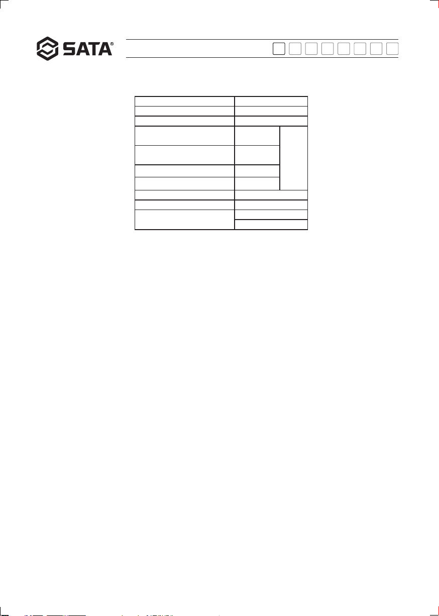
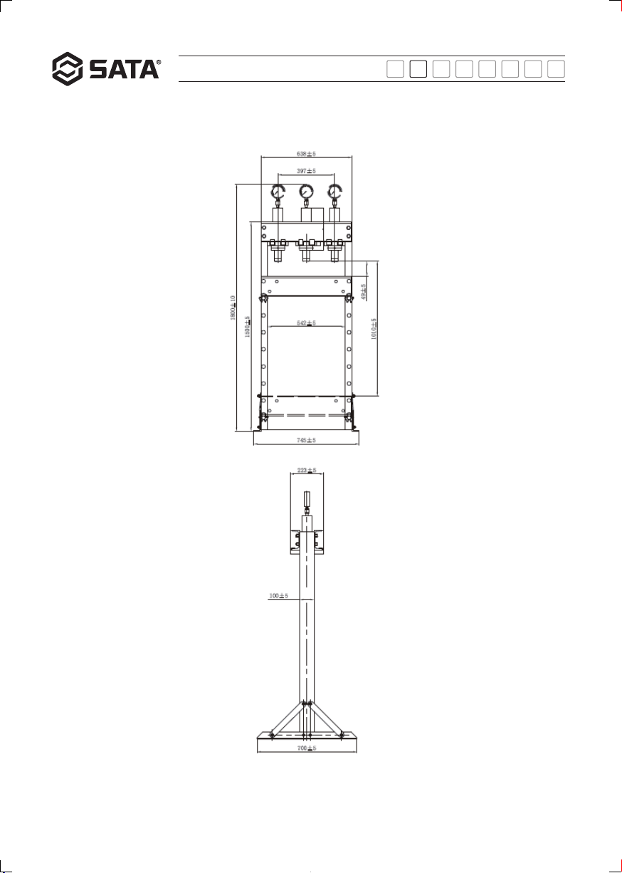
Product No. AE5831
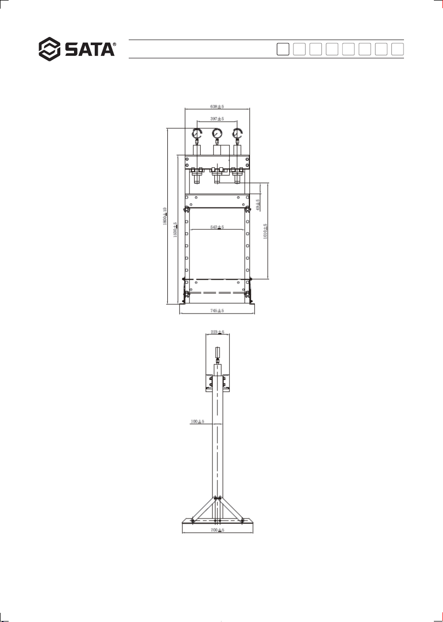
Product name 20t press
Rated weight (kg) 20000
Ram - working surface
Max. height (mm) 1010
±5
Ram - working surface
Minimum height (mm) 49
Moving distance of cylinder (mm) 397
Piston rod stroke (mm) 185
Net weight (kg) 94.5
Gross weight (kg) 98
Carton dimension (cm) 1# 155×19×14
2# 73×26×17
Operating instruction for 20t press:
AE5831
AE5831八国-200620.indd 8AE5831八国-200620.indd 8 2020/6/23 19:26:452020/6/23 19:26:45

9
透明度拼合
ESPT JARUEN DE KO
中文
AE5831
1.The heavy-duty bolts are used on the press, and shall be replaced with genuine parts.
2.Please select correct pressing attachments such as the ram, block, socket and bearing.
3.Do not expose the product to rain or use it outdoors in any adverse weather conditions.
4.Please keep it away from heat and fire sources, as high temperature may damage the equipment and seal.
5.The untrained personnel are not allowed to operate the equipment. Do not disassemble or modify the equipment by yourself.
6.It is recommended to reasonably maintain the equipment by professional technician with maintenance qualification. The genuine parts shall be used
for the necessary replacement.
7.Please wear safety shoes, goggles and working gloves conforming to relevant national safety regulations during operation, and SATA products are
recommended.
8.It is not allowed to use this product after drinking and in case of debilitation, inattention, drowsiness due to drugs and unconsciousness.
Warning: The Notes, Warnings, Tips in this Instruction cannot cover all possible conditions.
The operator shall understand that careful operation and professional knowledge are indispensable to operation of this product.
AE5831八国-200620.indd 9AE5831八国-200620.indd 9 2020/6/23 19:26:452020/6/23 19:26:45

10
透明度拼合
Overall dimension of the product:
ESPT JARUEN DE KO
中文
AE5831
AE5831八国-200620.indd 10AE5831八国-200620.indd 10 2020/6/23 19:26:452020/6/23 19:26:45

11
透明度拼合
Installation and operation:
Installation procedure:
1. Secure the LH footing, post and H-shaped rod with two M12 bolts, where the post opening shall face towards the H-shaped rod.
2. Secure the ends of the side support to the footing and post with four M10 bolts.
3. Repeat steps 1-2 to install and secure the RH footing, post and H-shaped rod.
4. Secure the rear piece of the upper cross-beam to the top of both posts with four M16 bolts, and insert the C-shaped groove on the cylinder plate
into the groove plate on the rear piece of the upper cross-beam.
5. Insert the groove plate on the front piece of the upper cross-beam into the C-shaped groove on the cylinder plate and secure the front piece of the
upper cross-beam to both posts with four M16 bolts.
6. When the lower cap has been removed, install the cylinder into the cylinder plate assembly, then re-install and tighten the lower cap with a C-hook
wrench.
7. Loose the pressure gauge plug counterclockwise with 24mm and 27mm wrenches to remove it, and install and tighten the pressure gauge on the
top of the cylinder with 27mm and 17mm wrenches.
8.Install the oil pump assembly on the rack of the right post with four M10 bolts.
9. Secure the pump pedal on the post rack and connect the pedal link to the oil pump with a cotter pin.
10. Assemble the lower cross-beam assembly with four M10 long bolts and four sleeves.
11.Insert 2 pins into the holes on the posts, secure them with retainer rings and install the posts in the lower cross-beam.
12. Loosen the filler vent nut before use.
Procedures before initial use:
1. Bleed the hydraulic system before initially using the press: turn the relief valve clockwise to close it, manually operate the pump to completely push
out the piston rod, and then loosen the relief valve, in this case the piston rod will automatically retract. Bleeding completes when the piston rod
has fully retracted.
Operation instructions:
1. Turn the relief valve (clockwise) to tighten it and manually operate the pump, the piston rod extends.
2. Turn the relief valve (counterclockwise) to loosen it and the piston rod automatically retracts.
3. Slide the cylinder plate to a position suitable for the workpiece. After that, please ensure that the cylinder plate is installed in place without tilting.
Instructions for bleeding:
1. When the equipment operates normally, the air is automatically bled via the oil circuit, thus there is no need to bleed manually.
Procedures for maintenance:
1. After use, be sure to loosen the oil return valve to return the knockout pin to its original position.
2.Regularly check the piston rod for rust and corrosion, and then apply a proper amount of lubricating oil after cleaning.
3.It is recommended to carry out annual inspection by professional technician.
Oil change requirement:
1. In order to ensure the best performance and service life of the product, please replace the hydraulic oil thoroughly at least once a year.
Oil level check:
1. Extend the piston rod completely and proceed to depress the pump pedal. When the oil is sufficient, great force is required to depress the
oil pump pedal. When the oil level is low, it requires little force to depress the pedal.
Procedures for filling oil:
1. Remove the plug screw on the oil pump, fill the oil pump with the right amount of high-quality hydraulic oil (until the oil level is 2cm lower
than the top edge), and then re-install the plug screw. Refer to Procedures before initial use to bleed the hydraulic system.
Oil change procedure:
1. The piston rod retracts to its position (the original position).
2. Remove the oil pipe joints near the hydraulic pressure gauge, remove the fixing bolts for oil pump and remove the parts of oil pump.
3. Remove the plug screw from the oil pump, turn the pump body over and drain the hydraulic oil to a suitable container.
4. Fill the oil pump with the right amount of high-quality hydraulic oil (≤ 0.95 liters) and re-install the plug screw.
5. Re-install the oil pump parts, tighten the joints, and connect the oil pipes.
6. Refer to Procedures before initial use to bleed the hydraulic system.
Note: Dispose the used hydraulic oil in accordance with local regulations.
ESPT JARUEN DE KO
中文
AE5831
AE5831八国-200620.indd 11AE5831八国-200620.indd 11 2020/6/23 19:26:452020/6/23 19:26:45

12
透明度拼合
ESPT JARUEN DE KO
中文
Exploded view and parts list
AE5831
Drawing No. SATA No. Part Name Qty
1 PAE5822-1 Dust ring 1
2 PAE5822-2 O-ring 1
3 PAE5822-3 Imported U-ring 1
4 PAE5822-4 Secondary cap 1
5 PAE5822-5 O-ring 1
AE5831八国-200620.indd 12AE5831八国-200620.indd 12 2020/6/23 19:26:452020/6/23 19:26:45

13
透明度拼合
ESPT JARUEN DE KO
中文
6 PAE5822-6 Secondary piston rod 1
7 PAE5822-7 Round-wire snap ring 1
8 PAE5822-8 Dust ring 1
9 PAE5822-9 O-ring 1
10 PAE5822-10 Imported U-ring 1
11 PAE5822-11 Primary cap 1
12 PAE5822-12 O-ring 1
13 PAE5822-13 Primary piston rod 1
14 PAE5822-14 Round-wire snap ring for stop 1
15 PAE5822-15 Plug 1
16 PAE5822-16 Hexagon socket set screw with flat point 1
17 PAE5822-17 Steel ball 1
18 PAE5822-18 O-ring 1
19 PAE5822-19 Cap base 1
20 PAE5822-20 Oil tank gasket 2
21 PAE5822-21 Oil tank assembly 1
22 PAE5821-17 Pin 1
23 PAE5821-18 Cotter pin 3
24 PAE5822-22 Handle 1
25 PAE5861-137 Handle cover 1
26 PAE5821-15 Filler vent screw 1
27 PAE5821-14 Combination gas-ket 1
28 PAE5822-23 Hydraulic cylinder 1
29 PAE5822-24 Hydraulic cylinder gasket 1
30 PAE5822-25 Pump body unit 1
31 PAE5822-26 U-shaped stop 2 1
32 PAE5822-27 Spring washer 1
33 PAE5822-28 Hexagon socket screw with flat round head 1
34 PAE5822-29 Drain pedal 1
35 PAE5822-30 Pin 1
36 PAE5822-31 Cotter pin 1
37 PAE5822-32 Plain washer 2
38 PAE5822-33 Pumping pedal assembly 1
39 PAE5821-25 Circlip for shaft 4
40 PAE5822-34 Connecting rod 2
41 PAE5822-35 Conveyor connecting rod pin 2
42 PAE5822-36 Pumping connect-ing rod pin 1
43 PAE5822-37 Footing assembly 2
44 PAE5821-5 Cap nut 4
45 PAE5821-6 Spring washer 4
46 PAE5821-7 Plain washer 4
47 PAE5822-38 Caster, with brake 2
48 PAE5821-46 Bracket head 1
48 PAE5822-39 Plain washer 4
49 PAE5822-40 Spring washerscrew 4
50 PAE5822-41 Hexagon bolt 4
51 PAE5822-42 Bracket head unit 1
52 PAE5822-43 Hexagonal socket screw 2
53 PAE5822-44 4” caster 2
AE5831
AE5831八国-200620.indd 13AE5831八国-200620.indd 13 2020/6/23 19:26:452020/6/23 19:26:45

14
透明度拼合
ESPT JARUEN DE KO
中文
Überprüfen Sie das Produkt sofort nach dem Auspacken, um sicherzustellen, dass das Produkt intakt ist.Wenn Teile fehlen oder beschädigt
sind, wenden Sie sich bitte an die Kundendienstabteilung von Sata Werkzeuge (Shanghai) GmbH: 400-820-3885, 800-820-3885
Bitte dokumentieren Sie die Seriennummer des Produkts: ___________________
Hinweis: Wenn das Produkt keine Seriennummer hat, notieren Sie sich bitte das Kaufdatum.
Bitte bewahren Sie dieses Handbuch an einem sicheren Ort auf:
1. In diesem Handbuch werden die Sicherheitshinweise, Installationsvorgänge, Wartungs- und Fehlerbehebungsmaßnahmen für das Produkt
beschrieben.
2. Notieren Sie die Seriennummer (oder das Kaufdatum) dieses Produkts auf der Titelseite des Handbuchs und bewahren Sie es an einem trockenen
und sicheren Ort auf.
3. Bitte verwenden Sie das Produkt korrekt nach dem Inhalt dieses Handbuchs.
4. Dieses Gerät ist gegen Produkthaftpflicht versichert.
Sicherheitswarnung:
1. Bitte lesen und verstehen Sie den Inhalt des Handbuchs sorgfältig, bevor Sie es verwenden.Unsachgemäße Handhabung kann zu Personen- und
Produktschäden führen.
2. Vor jedem Gebrauch sorgfältig prüfen, ob Öllecks, lose oder beschädigte Teile oder Zubehörteile vorhanden sind.
3. Es ist strengstens untersagt, das Gerät zu überlasten, ansonsten ist die Unfallhaftung nicht versichert.
4. Das Sicherheitsventil kann nicht selbst eingestellt werden, da sonst die Unfallhaftung nicht versichert ist.
5. Bitte halten Sie Kinder und anderes unbefugtes Personal vom Arbeitsbereich fern.
6. Bevor Sie auf das Werkstück drücken, üben Sie langsam Druck aus, um einen zuverlässigen Kontakt zu gewährleisten, und setzen Sie es dann unter
Druck.
7. Wenn Sie feststellen oder beurteilen, dass bleibende Verformungen auftreten können, stellen Sie die Verwendung sofort ein.
8. Verwenden Sie das Gerät auf einer ebenen, trockenen und zuverlässigen Oberfläche.
9. Bei diesem Gerät werden hochfeste Bolzen verwendet. Wenn Sie diese ersetzen müssen, verwenden Sie bitte Originalzubehör.
10.Bitte wählen Sie das richtige Druckzubehör wie z.B. die Oberplatte, den Block, die Hülse, um das Werkstück sicherzutragen.
11. Setzen Sie dieses Produkt keinem Regen aus und verwenden Sie es nicht im Freien bei widrigen Wetterbedingungen.
12.Vor Hitze und Feuer schützen. Hohe Temperaturen können das Gerät und die Dichtungskomponenten beschädigen.
13.Jedem ungeschulten Personal ist die Verwendung des Geräts strengstens untersagt und es darf das Gerät nicht zerlegt oder modifiziert werden.
14.Lassen Sie das Gerät von professionellem Wartungspersonal ordnungsgemäß warten. Wenn Sie das Zubehör austauschen müssen, verwenden Sie
bitte das Originalzubehör.
15.Während des Betriebs müssen Sicherheitsschuhe, Schutzbrillen und Arbeitshandschuhe getragen werden, die den einschlägigen nationalen
Sicherheitsbestimmungen entsprechen. Es wird empfohlen, Satas Produkte zu verwenden.
16.Es ist strengstens verboten, dieses Produkt nach dem Trinken, mit mangelnder Energie, mangelnder Konzentration, Benommenheit aufgrund von
Drogen und Bewusstlosigkeit zu verwenden.
Warnung: Die in diesem Handbuch enthaltenen Vorsichtsmaßnahmen, Warnungen, Anweisungen usw. decken nicht alle möglichen Bedingungen ab.
Der Bediener muss verstehen, dass ein umsichtiger Betrieb und Fachwissen für den Betrieb dieses Produkts von entscheidender Bedeutung sind.
Produktnummer AE5831
Produktname 20 T. Presse
Nenngewicht (kg) 20000
Oberplatte - Arbeitsfläche
Maximale Höhe (MM) 1010
±5
Oberplatte - Arbeitsfläche
Minimale Höhe (MM) 49
Bewegungsabstand vom Zylinder
(MM) 397
Kolbenstangenhub (MM) 185
Nettogewicht (kg) 94.5
Bruttogewicht (kg) 98
Außengröße des Kastens(CM) 1# 155×19×14
2# 73×26×17
Operating instruction for 20t press:
AE5831
AE5831八国-200620.indd 14AE5831八国-200620.indd 14 2020/6/23 19:26:452020/6/23 19:26:45

15
透明度拼合
Produktabmessungen:
ESPT JARUEN DE KO
中文
AE5831
AE5831八国-200620.indd 15AE5831八国-200620.indd 15 2020/6/23 19:26:462020/6/23 19:26:46

16
透明度拼合
ESPT JARUEN DE KO
中文
Wartung und Pflege:
1. Achten Sie nach dem Gebrauch darauf, das Ölrücklaufventil zu lösen, um die Auswurfstange wieder in ihre ursprüngliche Position zu
bringen.
2.Überprüfen Sie die Säulenkolbenstange regelmäßig auf Rost und Korrosion und tragen Sie nach der Reinigung eine angemessene Menge
Schmiermittel auf.
3.Es wird empfohlen, die jährliche Inspektion von professionellen Technikern durchführen zu lassen.
Anweisungen zum Ölwechsel:
1. Um die bestmögliche Leistung und Lebensdauer des Produkts zu gewährleisten, tauschen Sie das Hydrauliköl mindestens einmal jährlich
gründlich aus.
Ölstandskontrolle:
1. Ziehen Sie die Kolbenstange vollständig heraus und treten Sie weiter auf das Pumpenpedal.Wenn die Ölmenge ausreicht, muss das
Pumpenpedal kräftig gedrückt werden, um darauf zu treten.Wenn die Ölmenge fehlt, wenden Sie etwas Kraft an und das Pedal kann
durchgetreten werden.
Ölfüllschritte:
1. Entfernen Sie die Verschlussschraube von der Ölpumpe, spritzen Sie das entsprechende hochwertige Hydrauliköl ein (Füllen Sie 2 cm von
oben bis zum Flüssigkeitsstand auf) und installieren Sie dann die Verschlussschraube. Bitte beziehen Sie sich auf die Verwendung vor dem
ersten Gebrauch, die Luft im Hydrauliksystem abzulassen.
Ölwechselschritte:
1. Die Kolbenstange kehrt in ihre ursprüngliche Position zurück (in die Ausgangsposition zurückgezogen).
2. Entfernen Sie die Ölleitungsverbindung in der Nähe der Hydraulikanzeige, entfernen Sie die Befestigungsschraube der Ölpumpe und entfernen Sie
die Ölpumpenteile.
3. Entfernen Sie die Verschlussschraube von der Ölpumpe, drehen Sie den Pumpenkörper um und lassen Sie das Hydrauliköl in einem geeigneten
Behälter ab.
4. Füllen Sie das entsprechende hochwertige Hydrauliköl ein (Das ersetzte Hydrauliköl darf 0,95 Liter nicht überschreiten) und installieren Sie die
Verschlussschraube zurück.
5. Installieren Sie die Ölpumpenkomponenten zurück, ziehen Sie die Anschlüsse fest und schließen Sie die Schläuche an.
6. Bitte beziehen Sie sich auf die Verwendung vor dem ersten Gebrauch, die Luft im Hydrauliksystem abzulassen.
Hinweis: Entsorgen Sie verbrauchtes Hydrauliköl gemäß den örtlichen Vorschriften.
AE5831
Installation und Betrieb:
Installationsschritte:
1. Befestigen Sie einen Seitenfuß, eine Säule und eine Arbeitsstange mit 2 M12-Schrauben, wobei die Öffnungsrichtung der Säule zur Seite der
Arbeitsstange zeigt.
2. Befestigen Sie die beiden Enden des Zwickels an der unteren Ecke und der Säule mit 4 M10-Schrauben.
3. Wiederholen Sie die Schritte 1 bis 2, um den anderen Seitenfuß, die Säule und die 工-förmige Stange zu verbinden und zu sichern.
4. Befestigen Sie die hintere Platte des oberen Trägers mit 4 M16-Schrauben an der Oberseite der beiden Säulen und setzen Sie den C-förmigen
Kartenschlitz der Zylinderplatte in die hintere Platte des oberen Trägers ein.
5. Setzen Sie die obere Trägerplatte in den C-förmigen Schlitz der Zylinderplatte ein und befestigen Sie das Vorderteil des oberen Trägers mit 4 M16-
Schrauben an den beiden Säulen.
6. Setzen Sie den Zylinder nach dem Entfernen der unteren Kappe in die Zylinderplattenbaugruppe ein und die untere Kappe wieder auf. Verriegeln Sie
sie mit einem C-Schlüssel.
7. Nachdem Sie den Manometerstopfen mit einem 24-mm- und 27-mm-Schlüssel gegen den Uhrzeigersinn entfernt haben, bringen Sie das Manometer
mit einem 27-mm- und 17-mm-Schlüssel oben am Zylinder an und ziehen Sie es fest.
8.Bringen Sie die Ölpumpenbaugruppe mit 4 M10-Schrauben am Rahmen der rechten Säule an.
9. Befestigen Sie das Pumpenpedal am Säulenrahmen und verbinden Sie den Pedalhebel mit einem Splint mit der Ölpumpe.
10. Vervollständigen Sie die Unterbalkenbaugruppe mit 4 M10 langen Schrauben und 4 Buchsen.
11.Setzen Sie die 2 Stifte in das Loch der Säule ein, befestigen Sie sie mit dem Haltering und setzen Sie sie in den unteren Träger ein.
12. Lösen Sie die Tankentlüftungsmutter vor dem Gebrauch und lösen Sie sie.
Vor dem ersten Gebrauch:
1. Bevor Sie das Gerät zum ersten Mal in Betrieb nehmen, müssen Sie die Luft aus dem Hydrauliksystem entfernen: Drehen Sie das Überdruckventil
im Uhrzeigersinn ab, pumpen Sie die Kolbenstange manuelle, um diese vollständig auszuwerfen, und lösen Sie dann das Überdruckventil. Das
Auspuffen ist somit fertig.
Bedienungsanleitung:
1. Ziehen Sie das Druckbegrenzungsventil (im Uhrzeigersinn) fest, betreiben Sie die Pumpe manuell und die Kolbenstange funktioniert.
2. Lösen Sie das Druckbegrenzungsventil (gegen den Uhrzeigersinn) und die Kolbenstange fährt automatisch ein.
3.Die Zylinderplatte kann entsprechend der Position des Werkstücks in die richtige Position geschoben werden. Bitte stellen Sie nach dem
Verschieben sicher, dass die Zylinderplatte ohne Kippen an ihrem Platz installiert ist.
Auspuffbeschreibung:
1. Bei normalem Gebrauch des Geräts wird die Luft automatisch zusammen mit dem Ölkreislauf ohne manuelle Absaugung abgelassen.
AE5831八国-200620.indd 16AE5831八国-200620.indd 16 2020/6/23 19:26:462020/6/23 19:26:46

17
透明度拼合
Teilexplosionszeichnung und Liste
ESPT JARUEN DE KO
中文
AE5831
Zeichnungsnu
mmer
Sata-Nummer Zubehörname Verwendungs
menge
1 PAE5822-1 Staubring 1
2 PAE5822-2 O-Ring 1
3 PAE5822-3 Importierter U-Ring 1
4 PAE5822-4 Sekundäre Backenkappe 1
5 PAE5822-5 O-Ring 1
AE5831八国-200620.indd 17AE5831八国-200620.indd 17 2020/6/23 19:26:462020/6/23 19:26:46

18
透明度拼合
ESPT JARUEN DE KO
中文
AE5831
6 PAE5822-6 Sekundäre Kolbenstange 1
7 PAE5822-7
Drahtsicherungsring
1
8 PAE5822-8 Staubring 1
9 PAE5822-9 O-Ring 1
10 PAE5822-10 Importierter U-Ring 1
11 PAE5822-11 Backenkappe der ersten Stufe 1
12 PAE5822-12 O-Ring 1
13 PAE5822-13 Primäre Kolbenstange 1
14 PAE5822-14 Begrenzungsdrahtsicherungsring 1
15 PAE5822-15 Blinddeckel 1
16 PAE5822-16 Madenschraube mit Innensechskant 1
17 PAE5822-17 Stahlkugel 1
18 PAE5822-18 O-Ring 1
19 PAE5822-19 Backenkappensitze 1
20 PAE5822-20 Ölbehälterauflage 2
21 PAE5822-21 Baugruppe Ölbehälter 1
22 PAE5821-17 Stift 1
23 PAE5821-18 Splint 3
24 PAE5822-22 Griff 1
25 PAE5861-137 Griffschutzhülle 1
26 PAE5821-15 Entlüftungsschraube der Ölnachfüllung 1
27 PAE5821-14 Kombidichtung 1
28 PAE5822-23 Zylinder 1
29 PAE5822-24 Zylinderauflage 1
30 PAE5822-25 Pumpenkörperteile 1
31 PAE5822-26 U - Typenbegrenzung 2 1
32 PAE5822-27 Federauslage 1
33 PAE5822-28 Innensechskantschrauben mit Flach- und
Kugelkopf 1
34 PAE5822-29 Ölablasspedal 1
35 PAE5822-30 Stift 1
36 PAE5822-31 Splint 1
37 PAE5822-32 Flache Auflage 2
38 PAE5822-33 Ölpedalbaugruppe 1
39 PAE5821-25 Wellenhaltering 4
40 PAE5822-34 Pleuelstange 2
41 PAE5822-35 Trägerverbindungsstift 2
42 PAE5822-36 Pleuelstift für Ölpumpen 1
43 PAE5822-37 Fußbaugruppe 2
44 PAE5821-5 Hutmutter 4
45 PAE5821-6 Federauslage 4
46 PAE5821-7 Flache Auflage 4
47 PAE5822-38 Universalrad mit Bremse 2
48 PAE5821-46 Halterungskopf 1
48 PAE5822-39 Flache Auflage 4
49 PAE5822-40 Federauslage 4
50 PAE5822-41 Sechskantschraube 4
51 PAE5822-42 Haltekopfeinheit 1
52 PAE5822-43 Innensechskantschraube 2
53 PAE5822-44 4 "Universalrad 2
AE5831八国-200620.indd 18AE5831八国-200620.indd 18 2020/6/23 19:26:462020/6/23 19:26:46

19
透明度拼合
AE5831八国-200620.indd 19AE5831八国-200620.indd 19 2020/6/23 19:26:462020/6/23 19:26:46

20
透明度拼合
ESPT JARUEN DE KO
中文
Проверить продукт сразу после распаковки, чтобы убедиться, что продукт не поврежден.Если какие-либо детали отсутствуют или
повреждены, пожалуйста, свяжитесь с отделом обслуживания клиентов при ООО Шанхайской компании по производству инструментов
SATA: 400-820-3885, 800-820-3885
Пожалуйста, записать серийный номер продукта:________
Примечание: если у продукта нет серийного номера, записать дату покупки, пожалуйста.
Надлежащим образом хранить эту инструкцию по эксплуатации, пожалуйста:
1. Данная инструкция по эксплуатации содержит предупреждения о безопасности, операции по установке, техническое обслуживание и
устранение типичных неисправностей, связанные с продуктом, надлежащим образом хранить, пожалуйста.
2. Записать серийный номер (или дату покупки) этого продукта на первой странице инструкции по эксплуатации и хранить её в сухом и
безопасном месте для справки.
3. Пожалуйста, правильно использовать продукт на основе полного понимания содержания данной инструкции.
4. Это оборудование было застраховано для страхования продукта.
Предупреждения о безопасности:
1. Пожалуйста, внимательно прочитать и понимать все содержание инструкции перед использованием.Неправильное использование может
привести к личному повреждению и повреждению продукта.
2. Проверить внимательно перед каждым использованием, если есть утечка масла, ослабление или повреждение деталей или принадлежностей,
нельзя использовать.
3. Запрещается использовать это оборудование при перегрузке, в противном случае ответственность за несчастные случаи не покрывается
страховкой.
4. Предохранительный клапан не может быть регулирован сам по себе, в противном случае ответственность за несчастные случаи не
покрывается страховкой.
5. Обеспечить, что дети и другие посторонние лица отстоят далеко от рабочей зоны.
6. Перед сжатием изделия, сначала медленно оказать давление для обеспечения надежного контакта, потом приложить усилие для сжатия.
7. При обнаружении или определении возможной постоянной деформации, немедленно прекратить использование.
8. Использовать это оборудование на ровной, горизонтальной, сухой и надежной поверхности.
9. На этом оборудовании используются высокопрочные болты, если вам нужно заменить, пожалуйста, использовать оригинальные запчасти.
10.Выбрать правильные принадлежности для увеличения давления, например, вершина, подкладка, втулка, безопасные несущие изделия.
11. Не подвергать это продукт воздействию дождя и не использовать его на открытом воздухе при любых неблагоприятных погодных условиях.
12.Хранить вдали от источников тепла и огня, высокая температура может повредить продукт и уплотняющие компоненты.
13.Любому неподготовленному персоналу категорически запрещено использовать это оборудование, и нельзя самостоятельно разбирать или
модифицировать данное оборудование.
14.Пожалуйста, позволить специалисту с профессиональной квалификацией по ремонту разумно обслуживать оборудование, если нужно
заменить запчасти, использовать оригинальные запчасти, пожалуйста.
15.Во время работы необходимо носить защитную обувь, защитные очки и рабочие перчатки, соответствующие действующим национальным
правилам безопасности, рекомендуется использовать соответствующие продукты SATA.
16.Строго запрещается использовать данный продукт в случае алкогольного опьянения, слабого духа, снижения концентрации внимания,
усталости под воздействием лекарства и любого несознательного состояния.
Предупреждения: информация, такая как внимания, предупреждения, указания и т. д., содержащиеся в данном руководстве, не может охватывать
все возможные ситуации.
Операторы должны понимать, что ежедневная осторожная эксплуатация и наличие профессиональных знаний являются неотъемлемым фактором
при использовании этого продукта.
Номер продукции AE5831
Наименование товара Пресс 20 т
Номинальный вес, кг 20000
Вершина-рабочая поверхность
Максимальная высота, мм 1010
±5
Вершина-рабочая поверхность
Минимальная высота, мм 49
Расстояние перемещения
цилиндра, мм 397
Ход поршневого штока, мм 185
Вес нетто, кг 94.5
Вес брутто, кг 98
Размер внешней коробки, см 1# 155×19×14
2# 73×26×17
Operating instruction for 20t press:
AE5831
AE5831八国-200620.indd 20AE5831八国-200620.indd 20 2020/6/23 19:26:462020/6/23 19:26:46
Table of contents
Languages:
Other SATA Power Tools manuals
Popular Power Tools manuals by other brands

Hitachi
Hitachi RH 650V Handling instructions

BGS technic
BGS technic 8317 instruction manual

Chicago Pneumatic
Chicago Pneumatic RX 2 Safety and operating instructions

Porter-Cable
Porter-Cable PC600JS instruction manual

Milwaukee
Milwaukee Super Sawzall 6537-22 Operator's manual

AFF
AFF 42005 Instruction guide

PCB Piezotronics
PCB Piezotronics GK291E80 Installation and operating manual

Kernlochbohrer
Kernlochbohrer Skippy operating instructions

ETC
ETC EJS-750 Original instructions

Triton
Triton JOF001 Operating and safety instructions

Makita
Makita M9800KX4 instruction manual

Makita
Makita DJS200 instruction manual