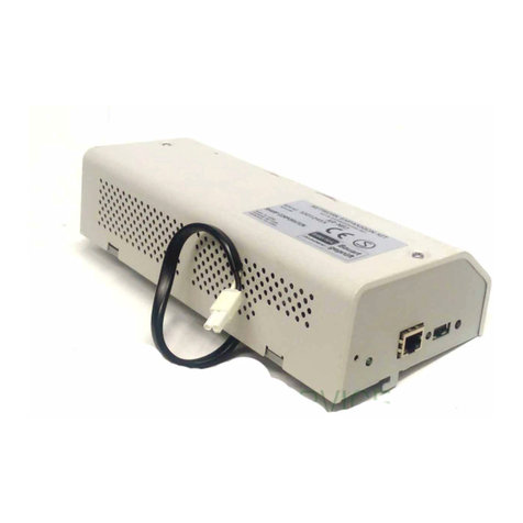
Sharp AR-P15 User manual

SHARP AR-P15
for the AR-651/810 series
SERVICE GUIDE
A guide for service technicians
Part Number: 4502XXXX


Copyright © 2002 Electronics For Imaging, Inc. All rights
reserved.
This publication is protected by copyright, and all rights are reserved. No part of it may be
reproduced or transmitted in any form or by any means for any purpose without express prior
written consent from Electronics For Imaging, Inc., except as expressly permitted herein.
Information in this document is subject to change without notice and does not represent a
commitment on the part of Electronics For Imaging, Inc.
The software described in this publication is furnished under license and may only be used or
copied in accordance with the terms of such license.
This product may be covered by one or more of the following U.S. Patents: 4,500,919,
4,837,722, 5,212,546, 5,343,311, 5,424,754, 5,467,446, 5,506,946, 5,517,334, 5,537,516,
5,543,940, 5,553,200, 5,615,314, 5,619,624, 5,625,712, 5,666,436, 5,760,913, 5,818,645,
5,835,788, 5,867,179, 5,959,867, 5,970,174, 5,982,937, 5,995,724, 6,002,795, 6,025,922,
6,041,200, 6,065,041, 6,112,665, 6,122,407, 6,134,018, 6,141,120, 6,166,821, 6,185,335,
6,201,614, 6,215,562, 6,219,659, 6,222,641, 6,224,048, 6,225,974, 6,226,419, 6,238,105,
6,239,895, 6,256,108, 6,269,190, 6,289,122, 6,292,270, 6,310,697, 6,327,047, 6,327,050,
6,327,052, RE36,947, D406,117, D416,550, D417,864, D419,185, D426,206, D439,851,
D444,793
Trademarks
ColorWise, EDOX, EFI, Fiery, the Fiery logo, Fiery Driven and RIP-While-Print are registered
trademarks of Electronics For Imaging, Inc. in the U.S. Patent and Trademark Office and/or
certain other foreign jurisdictions.
The eBeam logo, the Electronics For Imaging logo, the Fiery Driven logo, the Splash logo,
AutoCal, ColorCal, Command WorkStation, DocBuilder, DocBuilder Pro, DocStream,
eBeam, EFI Color Profiler, EFI Production System, EFI ScanBuilder, Fiery X2, Fiery X2e,
Fiery X2-W, Fiery X3e, Fiery X4, Fiery ZX, Fiery Z4, Fiery Z5, Fiery Z9, Fiery Z16, Fiery Z18,
Fiery Document WorkStation, Fiery Downloader, Fiery Driver, Fiery FreeForm, Fiery Link,
Fiery Prints, Fiery Print Calibrator, Fiery Production System, Fiery Scan, Fiery ScanBuilder,
Fiery Spark, Fiery Spooler, Fiery WebInstaller, Fiery WebScan, Fiery WebSpooler, Fiery
WebStatus, Fiery WebTools, NetWise, RIPChips, Splash, Velocity, Velocity Balance, Velocity
Build, Velocity Design, Velocity Estimate, Velocity Scan, and VisualCal are trademarks of
Electronics For Imaging, Inc.
All other terms and product names may be trademarks or registered trademarks of their
respective owners, and are hereby acknowledged.
Legal Notices
APPLE COMPUTER, INC. (“APPLE”) MAKES NO WARRANTIES, EXPRESS OR
IMPLIED, INCLUDING WITHOUT LIMITATION THE IMPLIED WARRANTIES
OF MERCHANTABILITY AND FITNESS FOR A PARTICULAR PURPOSE,
REGARDING THE APPLE SOFTWARE. APPLE DOES NOT WARRANT,
GUARANTEE, OR MAKE ANY REPRESENTATIONS REGARDING THE USE OR
THE RESULTS OF THE USE OF THE APPLE SOFTWARE IN TERMS OF ITS
CORRECTNESS, ACCURACY, RELIABILITY, CURRENTNESS, OR OTHERWISE.
THE ENTIRE RISK AS TO THE RESULTS AND PERFORMANCE OF THE APPLE
SOFTWARE IS ASSUMED BY YOU. THE EXCLUSION OF IMPLIED WARRANTIES
IS NOT PERMITTED BY SOME STATES. THE ABOVE EXCLUSION MAY NOT
APPLY TO YOU.
IN NO EVENT WILL APPLE, ITS DIRECTORS, OFFICERS, EMPLOYEES OR
AGENTS BE LIABLE TO YOU FOR ANY CONSEQUENTIAL, INCIDENTAL OR
INDIRECT DAMAGES (INCLUDING DAMAGES FOR LOSS OF BUSINESS
PROFITS, BUSINESS INTERRUPTION, LOSS OF BUSINESS INFORMATION, AND
THE LIKE) ARISING OUT OF THE USE OR INABILITY TO USE THE APPLE
SOFTWARE EVEN IF APPLE HAS BEEN ADVISED OF THE POSSIBILITY OF
SUCH DAMAGES. BECAUSE SOME STATES DO NOT ALLOW THE EXCLUSION
OR LIMITATION OF LIABILITY FOR CONSEQUENTIAL OR INCIDENTAL
DAMAGES, THE ABOVE LIMITATIONS MAY NOT APPLY TO YOU.
Apple’s liability
to you for actual damages from any cause whatsoever, and regardless of the form of the action
(whether in contract, tort [including negligence], product liability or otherwise), will be
limited to $50.
Restricted Rights Legends
For defense agencies: Restricted Rights Legend. Use, reproduction, or disclosure is subject to
restrictions set forth in subparagraph (c)(1)(ii) of the Rights in Technical Data and Computer
Software clause at 252.227.7013.
For civilian agencies: Restricted Rights Legend. Use, reproduction, or disclosure is subject to
restrictions set forth in subparagraph (a) through (d) of the commercial Computer Software
Restricted Rights clause at 52.227-19 and the limitations set forth in Electronics For Imaging’s
standard commercial agreement for this software. Unpublished rights reserved under the
copyright laws of the United States.
FCC Information
WARNING: FCC Regulations state that any unauthorized changes or modifications to this
equipment not expressly approved by the manufacturer could void the user’s authority to operate
this equipment.
Class A Compliance
This equipment has been tested and found to comply with the limits for a Class A digital device,
pursuant to Part 15 of the FCC Rules. These limits are designed to provide reasonable protection
against harmful interference when the equipment is operated in a commercial environment. This
equipment generates, and uses, and can radiate radio frequency energy and, if not installed and
used in accordance with the instruction manual, may cause harmful interference to radio
communications. Operation of this equipment in a residential area is likely to cause interference
in which case the user will be required to correct the interference at his own expense.
Industry Canada Class A Notice
This Class A digital apparatus complies with Canadian ICES-003.
Avis de Conformation Classe A de l’Industrie Canada
Cet appareil numérique de la Classe A est conforme à la norme NMB-003 du Canada.
RFI Compliance Notice
This equipment has been tested concerning compliance with the relevant RFI protection
requirements both individually and on system level (to simulate normal operation conditions).
However, it is possible that these RFI Requirements are not met under certain unfavorable
conditions in other installations. It is the user who is responsible for compliance of his particular
installation.
Dieses Gerät wurde sowohl einzeln als auch in einer Anlage, die einen normalen Anwendungsfall
nachbildet, auf die Einhaltung der Funkentstörbestimmungen geprüft. Es ist jedoch möglich, dass
die Funkentstörbestimmungen unter ungünstigen Umständen bei anderen Gerätekombinationen
nicht eingehalten werden. Für die Einhaltung der Funkentstörbestimmungen einer gesamten
Anlage, in der dieses Gerät betrieben wird, ist der Betreiber verantwortlich.
Compliance with applicable regulations depends on the use of shielded cables. It is the user who
is responsible for procuring the appropriate cables.
Die Einhaltung zutreffender Bestimmungen hängt davon ab, dass geschirmte Ausführungen
benützt werden. Für die Beschaffung richtiger Ausführungen ist der Betreiber verantwortlich.
Software License Agreement
YOU SHOULD CAREFULLY READ THE FOLLOWING TERMS AND CONDITIONS
BEFORE USING THIS SOFTWARE. IF YOU DO NOT AGREE TO THE TERMS AND
CONDITIONS OF THIS AGREEMENT, DO NOT USE THE SOFTWARE. INSTALLING
OR USING THE SOFTWARE INDICATES THAT YOU AGREE TO AND ACCEPT THE
TERMS OFTHIS AGREEMENT. IF YOU DO NOT AGREE TO ACCEPT THE TERMS OF
THIS AGREEMENT YOU MAY RETURN THE UNUSED SOFTWARE FOR A FULL
REFUND TO THE PLACE OF PURCHASE.
License
EFI grants you a non-exclusive license to use the software (“Software”) and accompanying
documentation (“Documentation”) included with the Product. The Software is licensed, not sold.
You may use the Software solely for your own customary business or personal purposes. You may
not rent, lease, sublicense or lend the Software. You may, however, permanently transfer all of your
rights under this Agreement to another person or legal entity provided that: (1) you transfer to the
person or entity all of the Software and Documentation (including all copies, updates, upgrades,
prior versions, component parts, the media and printed materials, and this Agreement); (2) you
retain no copies of the Software and Documentation, including copies stored on a computer; and
(3) the recipient agrees to the terms and conditions of this Agreement.
You may not make or have made, or permit to be made, any copies of the Software or portions
thereof, except as necessary for backup or archive purposes in support of your use of the Software
as permitted hereunder. You may not copy the Documentation. You may not attempt to alter,
disassemble, decompiler, decrypt or reverse engineer the Software.
Proprietary Rights
You acknowledge that the Software is proprietary to EFI and its suppliers and that title and other
intellectual property rights therein remain with EFI and its suppliers. Except as stated above, this
Agreement does not grant you any right to patents, copyrights, trade secrets, trademarks (whether
registered or unregistered), or any other rights, franchises or licenses in respect of the Software. You
may not adopt or use any trademark or trade name which is likely to be similar to or confusing
with that of EFI or any of its suppliers or take any other action which impairs or reduces the
trademark rights of EFI or its suppliers.
Confidentiality
You agree to hold the Software in confidence, disclosing the Software only to authorized users
having a need to use the Software as permitted by this Agreement and to take all reasonable
precautions to prevent disclosure to other parties.
Remedies and Termination
Unauthorized use, copying or disclosure of the Software, or any breach of this Agreement will
result in automatic termination of this license and will make available to EFI other legal
remedies. In the event of termination, you must destroy all copies of the Software and all of its
component parts. All provisions of this Agreement relating to disclaimers of warranties,
limitation of liability, remedies, damages, and EFI’s proprietary rights shall survive
termination.
Limited Warranty and Disclaimer
EFI warrants to the original purchaser (“Customer”) for thirty (30) days from the date of
original purchase from EFI or its authorized retailer that the Software will perform in
substantial conformance to the Documentation when the Product is used as authorized by
EFI’s specifications. EFI warrants the media containing the Software against failure during the
above warranty period. EFI makes no warranty or representation that the Software will meet
your specific requirements, that the operation of the Software will be uninterrupted or error
free, or that all defects in the Software will be corrected. EFI makes no warranty, implied or
otherwise, regarding the performance or reliability of any third party products (software or
hardware) not provided by EFI. THE INSTALLATION OF ANY THIRD PARTY
PRODUCTS OTHER THAN AS AUTHORIZED BY EFI WILL VOID THIS
WARRANTY. IN ADDITION, USE, MODIFICATION, AND/OR REPAIR OF THE
PRODUCT OTHER THAN AS AUTHORIZED BY EFI WILL VOID THIS
WARRANTY.
EXCEPT FOR THE ABOVE EXPRESS LIMITED WARRANTY, EFI MAKES AND YOU
RECEIVE NO WARRANTIES OR CONDITIONS ON THE SOFTWARE, EXPRESS,
IMPLIED, STATUTORY, OR IN ANY OTHER PROVISION OF THIS AGREEMENT
OR COMMUNICATION WITH YOU, AND EFI SPECIFICALLY DISCLAIMS ANY
IMPLIED WARRANTY OR CONDITION OF MERCHANTABILITY OR FITNESS
FOR A PARTICULAR PURPOSE OR NONINFRINGEMENT OF THIRD PARTY
RIGHTS.
Limitation of Liability
TO THE MAXIMUM EXTENT PERMITTED BY LAW, EFI AND ITS SUPPLIERS SHALL
NOT BE LIABLE FOR ANY DAMAGES, INCLUDING LOSS OF DATA, LOST PROFITS,
COST OF COVER OR OTHER SPECIAL, INCIDENTAL, CONSEQUENTIAL OR
INDIRECT DAMAGES ARISING FROM THE SALE, INSTALLATION, MAINTENANCE,
USE, PERFORMANCE OR FAILURE OF THE SOFTWARE, HOWEVER CAUSED AND
ON ANY THEORY OF LIABILITY. THIS LIMITATION WILL APPLY EVEN IF EFI HAS
BEEN ADVISED OF THE POSSIBILITY OF SUCH DAMAGE. YOU ACKNOWLEDGE
THAT THE PRICE OF THE PRODUCT REFLECTS THIS ALLOCATION OF RISK.
BECAUSE SOME JURISDICTIONS DO NOT ALLOW THE EXCLUSION OR
LIMITATION OF LIABILITY FOR CONSEQUENTIAL OR INCIDENTAL DAMAGES,
THE ABOVE LIMITATION MAY NOT APPLY TO YOU.
Export Controls
You agree that you will not export or re-export the Software in any form in violation of any
applicable laws or regulations of the United States or the country in which you obtained them.
U.S. Government Restricted Rights:
The Software and Documentation are provided with RESTRICTED RIGHTS. Use, duplication,
or disclosure by the United States Government is subject to restrictions as set forth in
subparagraph (c)(1)(ii) of the Rights in Technical Data and Computer Software clause at DFARS
252.227-7013 or subparagraphs (c)(1) and (2) of the Commercial Computer Software Restricted
Rights at 48 CFR 52.227-19, as applicable.
General
The laws of the State of California govern this Agreement. You agree that this Agreement shall not
be subject to the United Nations Convention on Contracts for the International Sale of Goods
(1980). This Agreement is the entire agreement held between us and supersedes any other
communications or advertising with respect to the Software. If any provision of this Agreement is
held invalid, the remainder of this Agreement shall continue in full force and effect.
If you have any questions, please see EFI’s web site at www.efi.com.
Electronics For Imaging
303 Velocity Way
Foster City, CA 94404

Contents
v
Overview
1
Accessing the AR-P15
3
Checking connections
4
LEDs and jumpers
5
Replacing AR-P15 components
5
Replacing the AR-P15 motherboard 6
Replacing or adding a DIMM 7
Restoring functionality after service
8
Using the Control Panel
9
Startup 10
Online/Offline 10
Printing AR-P15 pages 13
Verifying connection to the network
15
Verifying the parallel port connection
16
System Software
18
System Software installation reminders 18
Installing System Software 19
Using TopAccess to view and export the Setting Code
22
Requirements 22
Specifications
26
Hardware features 26
Networking and connectivity 26
User software 26
Safety and emissions compliance 26
The troubleshooting process
27
Where problems occur
28
Before you go to the customer site
29
Preliminary on-site checkout
30
Checking connections 30
Checking the network 32
Printing to the AR-P15 32
Index


1
Overview
Overview
The Sharp AR-P15 Network Printer Board embeds computer connectivity and highly
efficient PCL printing capacity into the Sharp AR-651/810 series of digital copiers. The
Sharp AR-P15 Network Printer Board is shipped with all necessary software already
installed.
This guide refers to the Sharp AR-P15 Network Printer Board as the “AR-P15” and
refers to the Sharp AR-651/810 series as the “copier”.
The AR-P15 provides the Ethernet networking interface, handles the communication
with external devices, and controls (optional) hard disk drive functions. The on-board
CPU controls the printing image data transferred to and from the copier. Standard
on-board memory totals 128MB, supplied in one DIMM in J49.
Optional upgrades for the AR-P15 include:
•PostScript option—PostScript (PS) key chip for motherboard socket U800
•Hard disk drive (HDD) option—HDD key chip for motherboard socket U800,
HDD, and HDD ribbon cable for motherboard connector J207.
•Memory option—one additional 128MB DIMM for motherboard socket J48
This guide describes how to service the AR-P15, including how to reinstall system
software, if necessary. Generally, the AR-P15 does not require regular maintenance. Use
the procedures in this guide to inspect, remove, reseat, or replace major hardware
components and to reinstall system software.
This document includes information on:
• AR-P15 motherboard and chassis (page 6)
• AR-P15 memory (page 7)
•System software (page 18)
You will need to reinstall system software if you:
•Replace the optional hard disk drive
•Upgrade to a more recent version of the system software
Spares for the AR-P15 are available from your authorized service support center.
On the standard AR-P15, system software resides in flash memory. When the AR-P15 is
configured with the HDD option, system software resides in the HDD.

2
Overview
F
IGURE
A
AR-P15 exploded view
Key
1. AR-P15 motherboard
2. Connector to copier
3. Key chip socket for PostScript option or
HDD option (U800)
4. CPU cooling assembly
5. DIMM
6. DIMM sockets
7. Socketed BIOS chip (U202)
8. Optional HDD cable (for HDD option)
9. Optional HDD
10. Optional key chip
11. Network activity LEDs
12. RJ-45 network connector
13. Parallel port connector
14. AR-P15 chassis with faceplate
9
7
11
8
6
5
4
3
2
1
12
14
13
10

3
Accessing the AR-P15
In order to service the AR-P15, power off and unplug the copier, and then remove the
AR-P15. See AR-P15 installation instructions (not provided in this guide).
F
IGURE
B
AR-P15 installed in the copier
Network activity LEDs (2)
Copier side panel
10BaseT/100BaseTX connector
for twisted pair Ethernet
Parallel port connector
AR-P15

4
Checking connections
The most common causes of hardware problems are faulty or loose connections.
First verify the following external connections:
•Network connection at the faceplate
•Parallel port connection at the faceplate
Then verify the following internal connections:
• AR-P15 connection to the copier at J924
• DIMMs J49 (and J48, with upgrade)
•Optional key chip in motherboard socket U800 (the PS key chip and HDD key chip
are not the same chip)
•Optional HDD cable connection at J207
T
O
CHECK
INTERNAL
CONNECTIONS
1. Before you touch any parts inside the copier, wear an ESD grounding strap and follow
standard ESD (electrostatic discharge) precautions.
2. Inspect internal ribbon cables, if any, to see if they are intact.
Faulty ribbon cables are easily overlooked. Check the contact point between the optional
HDD cable and the HDD for separation. Make sure the HDD cable is locked into place
in the connector at J207. If a ribbon cable is suspect, substitute it with a tested cable. The
cable is keyed to fit the AR-P15 connector in only one way (the non-gray line on the
ribbon cable to Pin 1 on the AR-P15 board silkscreen).
3. Make sure that any AR-P15 cables, DIMMs, or other socketed components are properly
aligned and well seated on their connectors.
• Check the AR-P15 motherboard connection to the copier. This connection is for the
printer interface and the Control Panel interface, and for receiving power from the
copier power supply.
•Check the connection for each DIMM installed (one if standard, two if upgraded). See
page 7.
•Inspect for bent or broken pins on the optional key chip. These pins are delicate. If
bent, carefully straighten them with a pair of needlenose pliers. Carefully align the 8
pins of the chip with the socket before you insert the chip. Also note that the PS key
chip is not the same as the HDD key chip. (Instructions for installing optional
components are not provided in this guide.)
4. After verifying connections, if one or more AR-P15 components is still not getting
power, check the copier power supply (see copier documentation).

5
LEDs and jumpers
LEDs and jumpers
Activity indicators
—Adjacent to the on-board RJ-45 connector, two green LEDs
indicate network activity and link speed. One LED indicates network activity and lights
when data is present; therefore, it blinks during data transmission. The other LED
indicates link speed and lights at 100Mbps and turns off at 10Mbps.
Jumpers
—No jumpers are installed in the standard configuration.
Replacing AR-P15 components
N
OTE
:
Before performing these procedures, you must power off and unplug the copier,
and remove the AR-P15 from the copier. See the AR-P15 installation instructions (not
provided in this guide).
The AR-P15 has two DIMM sockets: one 128MB DIMM in J49 and, optionally,
another 128MB DIMM in J48 (see Figure A on page 2 and also “Replacing or adding a
DIMM” on page 7).
When the AR-P15 is installed inside the copier, the connectors for external devices are
easily accessible at the faceplate (see Figure G on page 15).
Wear an ESD grounding wrist strap and follow standard ESD (electrostatic discharge)
precautions while performing these procedures.
F
IGURE
C
AR-P15 layout
Key
1. AR-P15 motherboard
2. Connector to copier
3. Key chip socket for PostScript option or
HDD option (U800)
4. CPU cooling assembly
5. DIMM
6. DIMM sockets
7. Socketed BIOS chip (U202)
8. Optional HDD cable (for HDD option)
9. Optional HDD
10. Optional key chip (for HDD)
11. Network activity LEDs
12. RJ-45 network connector
13. Parallel port connector
9
7
11
8
6
5
4
3
2
1
12
13
10

6
Replacing AR-P15 components
Replacing the AR-P15 motherboard
When the AR-P15 motherboard needs to be replaced, use the following procedure. See
Figure A on page 2 for screw locations.

T
O
REPLACE
THE
AR-P15
MOTHERBOARD
Wear an ESD grounding strap and follow standard ESD (electrostatic discharge)
precautions while performing this procedure.
1. Shut down the copier and remove the AR-P15 from the copier (according to the
installation instructions, not provided in this guide).
2. Remove and set aside the 6 screws that attach the motherboard to the chassis.
3. Remove and set aside the 2 screws that attach the parallel port connector to the chassis.
4. Remove the motherboard from the chassis.
5. Remove the following standard components from the motherboard:
• DIMM in J49 (See page 7)
6. Remove any of the following optional components from the motherboard:
•Optional DIMM in J48
•Optional HDD, if present
•Optional key chip in U800, if present (see Figure C on page 5 for location)
Instructions for removing optional components are not provided in this guide.
7. Unpack the new motherboard.
8. Install the standard components you removed earlier onto the new motherboard.
To reinstall memory, see page 7.
9. Install any optional components you removed earlier onto the new motherboard.
Inspect for bent or broken pins on the optional key chip. These pins are delicate. If bent,
carefully straighten them with a pair of needlenose pliers. Carefully align the 8 pins of the
chip with the socket before you insert the chip. Also note that the PS key chip is not the
same as the HDD key chip. (Instructions for installing optional components are not
provided in this guide.)
10. Install the new motherboard into the chassis using the 8 screws you removed earlier:
•6screws attach the motherboard to the chassis
•2screws attach the parallel port connector to the chassis.
11. Reassemble the unit and verify functionality (see page 8).

7
Replacing AR-P15 components
Replacing or adding a DIMM
Each DIMM (dual in-line memory module) is held in place by a lever at each end of its
socket on the AR-P15.
The standard configuration for the AR-P15 is one 128MB DIMM installed in socket
J49. To upgrade to 256MB, install an additional 128MB DIMM in socket J48.
Approved DIMMs are available from your authorized service support center.
T
O
REPLACE
OR
ADD
A
DIMM
1. To release a DIMM, push outward on the lever on each side of the DIMM (see Figure D).
F
IGURE
D
Releasing a DIMM
2. Pull the DIMM straight out of the socket to avoid damaging it or the socket, and set the
DIMM aside.
3. To install a DIMM, insert it straight into the socket. Push the DIMM into the socket until
the levers snap into place.
The DIMM fits the socket only one way. The two notches on the bottom of the DIMM
should line up with the notches in the socket.
Make sure the levers close securely around the ends of the DIMM. Avoid flexing the
board while you firmly seat the DIMM in its socket.
4. Reassemble the unit and verify functionality (see page 8).
To verify memory capacity, print a Setting List to check the amount of memory recorded.
Lever
Socket notches
DIMM

8
Restoring functionality after service
To complete any service procedures performed on the AR-P15, install the AR-P15 inside
the copier, as described in the AR-P15 installation instructions (not provided in this
guide) and verify it is working properly. To verify the installation, check the connections
of the AR-P15, first to the copier and then the network, and the parallel port.
T
O
REASSEMBLE
AND
VERIFY
THE
AR-P15
1. Reseat any boards, cables, connectors, and other parts of the AR-P15 you loosened or
removed during inspection or service.
2. Install the AR-P15 in the copier and reassemble the copier as described in the AR-P15
installation instructions (not provided in this guide).
3. If you replaced the optional HDD, reinstall system software according to the procedure in
“System Software” on page 18.
4. Before you leave the customer site, verify AR-P15 operation, as described in the
following flow diagram.
F
IGURE
E
AR-P15 connection verification steps
Power up and print test pages
(see page 13).
Check the AR-P15 settings. For more
information on setting up the AR-P15,
see the Administrator’s Guide.
Connect the AR-P15 to the network
and/or parallel port and verify (see
page 15 and/or page 16).

9
Using the Control Panel
The LCD on the copier Control Panel is a touch panel display. You can use the copier
Control Panel to check AR-P15 status and perform AR-P15 functions, such as print test
pages. The PRINTER/NETWORK button accesses AR-P15 LCD screens.
F
IGURE
F
Control Panel with LCD (touch panel display)
HELP
TIMER
INTERRUPT
STOP
START
FC
FUNCTION CLEAR
ENERGY SAVER
JOB STATUS
COPY
PRINTER/
NETWORK
DATA
ERROR
1 2 3
4 5 6
7 8 9
0
?
C
Location of copier power switch

10
Using the Control Panel
Startup
To power on the copier, use the power switch located on the top left side of the copier
(see Figure F). At each power up, the AR-P15 takes approximately 5 minutes to initialize.
Before the AR-P15 is ready, the following screen is displayed if you press the PRINTER/
NETWORK button on the Control Panel.
When the AR-P15 is ready, the message “Printer is under preparation...” disappears.
Online/Offline
To use the Control Panel LCD for certain AR-P15 functions, such as printing test pages,
you must take the AR-P15 offline before you perform the function, and then put the
AR-P15 back online when you are done.
When the AR-P15 is online, it can receive data over the network from a networked
computer. When the AR-P15 is offline, it cannot receive data over the network from a
networked computer.
Icons on the Control Panel LCD indicate ON LINE/OFF LINE status. To change
AR-P15 status, touch the appropriate icon. See the following procedures.
PRIVATE
Printer is under preparation...

11
Using the Control Panel
T
O
TAKE
THE
AR-P15
OFFLINE
1. Press the Printer/Network button on the Control Panel, and then touch the ON/OFF tab.
2. Touch the OFF LINE icon.
When the AR-P15 is offline, the following screen is displayed:
To return to the main copier screen, press the COPY button on the Control Panel or
allow Printer/Network mode to time out.
PRIVATE

12
Using the Control Panel
TOPUT THE AR-P15 ONLINE
1. Press the Printer/Network button on the Control Panel, and then touch the ON/OFF tab.
2. Touch the ON LINE icon.
3. When the AR-P15 is online, the following screen is displayed.
To return to the main copier screen, press the COPY button on the Control Panel or
allow Printer/Network mode to time out.
PRIVATE

13
Using the Control Panel
Printing AR-P15 pages
The Control Panel LCD allows you to print pages that are generated from the AR-P15.
These pages include the PCL Test page, PS Test page (only with the PostScript option
installed), Fonts List, Setting List, Storage List, and Print Log.
The Setting List shows the current configuration. Before you perform any service
procedure, print the AR-P15 Setting List (if possible) so that you can return the settings
to their former configuration, if necessary.
After the connection to the network is made, the network administrator can customize
AR-P15 settings according to the network and user environment. Using the Setting List
as a guide can help speed up this process. For more information on setting up the
AR-P15, see the Administrator’s Guide.
Printing the PCL and PS Test pages
Before connecting the AR-P15 to the network, print the test page for PCL (Printer
Control Language). If the PS option or HDD option is installed, also print the test page
for PS (PostScript). Test pages are files that reside in the AR-P15. Output verifies that the
AR-P15 is functional and connected properly to the copier.

14
Using the Control Panel
TOPRINT AR-P15 PAGES FROM THE CONTROL PANEL LCD
1. Take the AR-P15 offline, as described on page 11.
Touch the UTILITY tab on the Control Panel LCD.
2. Touch the TEST PRINTING icon on the Control Panel LCD.
3. Touch the icon for the particular page to be printed: Setting List, Fonts List, PCL Test,
PS Test, Storage List, or Print Log.
NOTE:The PS Test page icon appears only if the PostScript option or HDD option is
installed.
4. Examine the PCL Test Page (and PS Test Page, if available).
If the PCL (or PS) Test Page prints, you know the AR-P15 print engine is functional and
the connection between the AR-P15 and the copier is operating properly. When you
examine the PS Test Page, keep in mind that:
•All swatches should be visible, even though they may be very faint in the lowest ranges.
•Swatches should show uniform gradation as the tone lightens.
•Poor image quality may indicate a need to calibrate the system or service the copier.
5. Post the current Setting List near the server for quick reference.
Users may need the information on this page.
6. Put the copier back online, as described on page 12.
If the AR-P15 is not connected to the network yet, proceed to page 15 to connect and
verify the AR-P15 connection to the network.
UTILITY tab
Table of contents
Other Sharp Printer Accessories manuals

Sharp
Sharp MX-FX12 Guide

Sharp
Sharp AR-D24 User manual

Sharp
Sharp AR-PB2A User manual

Sharp
Sharp MX-CFX1 User manual

Sharp
Sharp AR-DU3 User manual

Sharp
Sharp AR-FN7 User manual

Sharp
Sharp AR-PB8 User manual

Sharp
Sharp ARFX13 - Fax Interface Card User manual

Sharp
Sharp AR-PB9ML User manual

Sharp
Sharp FO-1MK User manual

Sharp
Sharp AR-PB2A User manual

Sharp
Sharp AR-FR11 User manual

Sharp
Sharp ARFX13 - Fax Interface Card User manual

Sharp
Sharp AR-NB3 User manual

Sharp
Sharp AR-FX12 User manual

Sharp
Sharp AM-300 User manual

Sharp
Sharp ARNC5J User manual

Sharp
Sharp MX-B201D User manual

Sharp
Sharp AR-NS1 User manual

Sharp
Sharp AR-FR19 U User manual