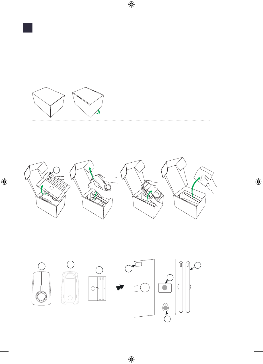
8
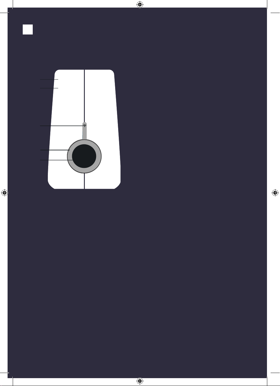
Components & features
Card/key fob reader
This is the area where you scan your charge card
or key fob for SMART WALL BOX and WALL BOX
with activated RFID card/key fob. The wall box
reads the data from your card to start or stop a
charging session.
Operating system
Start and stop your charging session according to
your wall box model:
WALL BOX:
Plug your charging cable into the wall box an into
the car to start charging.
WALL BOX with activated RFID card/key fob:
Plug your charging cable into the wall box and
into the car and hold your RFID card / key fob in
front of RFID reader to start charging.
SMART WALL BOX:
Equipped with Wi-Fi, UMTS and kWh meter.
Plug your charging cable into the wall box and
into the car and hold your RFID card / key fob in
front of RFID reader to start charging and track
your sessions online.
1
2
3
5
Housing
The wall box consists of a wall dock and a wall
box.
The wall box is designed with rugged, high-im-
pact strength plastics that make its housing dura-
ble, robust, weather-resistant and wear-resistant.
Socket with shutter
Wall Box with a socket offers you the opportunity
to make use of your own charging cable.
The socket is standard Type 2, provided with an
integrated shutter system.
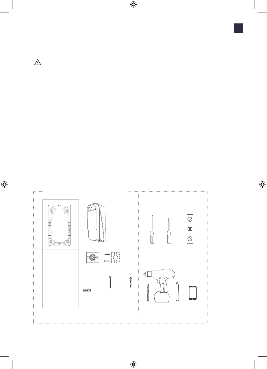
A mode 3 charging cable is required to charge
your electric vehicle. Please contact your car
dealer for more information.
Product Classication
• EV Supply Equipment connected to AC supply network
• Electric connection method: permanently connected
• AC EV Supply Equipment
• Outdoor use
• Equipment for locations with non-restricted access
• Stationary equipment, mounted on walls, poles or equivalent means: surface mounted
• Class I Equipment
• Mode 3 EVSE
• Operating temperature range: -25°C to 45°C
• Enclosure ratings: IP55, IK10
LED indicator
This smart status indicator helps you understand
what the wall box is doing at all times.
4
1
2
3
4
5
EN
INSTALLATION_WALL_BOX_SOCKET_PSA_B2C_MERGED.indd 8 11-9-2019 8:29:33
Part number: 9835662680