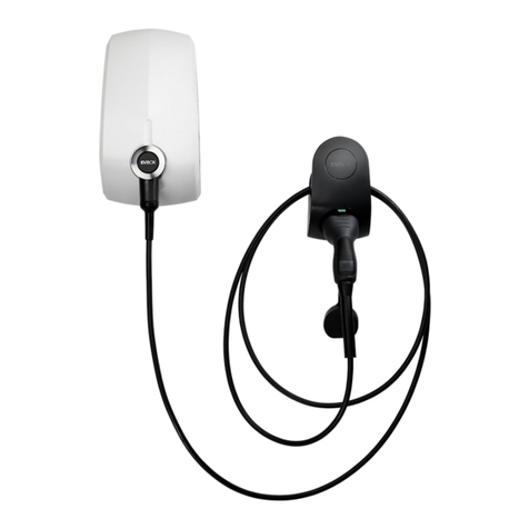
EVBox 9835662780 User manual

t
WALL BOX
Installation manual
(EN) Installation manual 4
(DE) Installationshandbuch 25
(FR) Manuel d’installation 46
(ES) Manual de instalación 67
(NL) Installatiehandleiding 88
(NO) Installasjonsveiledning 109
(IT) Manuale di installazione 130
(PT) Manual de instalação 151
(PL) Instrukcja montażu 172
INSTALLATION_WALL_BOX_PSA_B2C_COVER_MERGED.indd 2 23/09/2019 17:48
Part number: 9835662780

3
(EN) Installation manual 4
(DE) Installationshandbuch 25
(FR) Manuel d’installation 46
(ES) Manual de instalación 67
(NL) Installatiehandleiding 88
(NO) Installasjonsveiledning 109
(IT) Manuale di installazione 130
(PT) Manual de instalação 151
(PL) Instrukcja montażu 172
INSTALLATION_WALL_BOX_PSA_B2C_MERGED.indd 3 11-9-2019 8:30:37
Part number: 9835662780

WALL BOX
EN
Installation manual
INSTALLATION_WALL_BOX_PSA_B2C_MERGED.indd 4 11-9-2019 8:30:37
Part number: 9835662780

5
Contents
Contents 5
Safety precautions 6
Product description 7
Components & features 8
1. Unpack wall box 10
2. Install wall dock 11
3. Install charging cable 17
4. Install wall box 18
5. Activate wall box 19
6. Troubleshooting 21
7. Declaration of conformity 24
EN
INSTALLATION_WALL_BOX_PSA_B2C_MERGED.indd 5 11-9-2019 8:30:37
Part number: 9835662780

6
Safety precautions
EN
Warning: Risk of electric shock.
• Read the supplied documentation carefully to familiarize yourself with all safety
instructions and regulations before using this product.
• This product is designed and tested in accordance with international standards.
• The use of this product is limited to those applications it is designed for.
• Installation, maintenance and repairs of this product are only to be performed by
qualied personnel.
• Incorrect installation or repairs may cause hazardous situations for the user of this
product.
• This product is used in combination with a power source.
• Always switch off power before any maintenance activity.
• This product contains no user-serviceable parts. Consult your distributor for more
information. Do not attempt to service or repair the wall box yourself!
• Make sure that the product is only used under the correct operating conditions.
• Make sure that the main power is disconnected before storing or transporting
this product.
• Make sure that the power line to wall box is installed on a dedicated circuit
breaker (MCB) on your service panel. The installation, including the residual-
current device (RCD), must be according to local regulations and IEC 60364.
The MCB rating must not exceed the current rating of the wall box or the power
supply cable within the installation. In case the maximum current rating of the
wall box is higher than the current allocated for the wall box, the installer must
adjust the internal current rating of the wall box using the EVBox Connect App
(which must be installed on their mobile device).
• To maximize the power output of the wall box, install the wall box in
surroundings not subject to extreme sunlight, this reduces de-rating of the wall
box due to excessive temperatures.
• Store this product in a dry environment; the storage temperature must be
between -25 °C and +60 °C.
• The installing party must always ensure that the wall box is installed according to
the local regulations. The installation settings of the service panel must always be
adjusted by a qualied electrician.
• The supplier is not responsible for any damage that occurs if this product is
transported in a different packaging than the packaging in which the product was
originally supplied.
INSTALLATION_WALL_BOX_PSA_B2C_MERGED.indd 6 11-9-2019 8:30:38
Part number: 9835662780

7
EN
Product description
Product conguration
The table below contains the available product congurations for the wall box. This manual covers
the wall box versions with xed charging cable. For wall box models with socket and shutter (refer-
ence number 9835663080 and 9835662680), see the installation manual for wall box with socket and
shutter.
PSA Power Vehicle connections
(IEC 62196) Connectivity
PSA
reference
number
PSA
description Installation Maximum
output
power
Fixed cable
6m. with
charge
plug type 2
Socket
type
2 with
shutter
Auto-
start
default
Back-
end
ready
9835662980 WALL BOX
11 kW C 3P+N+PE
- 16 A -
230/400 Vac
11 kW • - • -
9835663180 SMART
WALL BOX
7,4 kW C
1P+N+PE -
32 A - 230
Vac
7,4 kW • - - •
9835662780 SMART
WALL BOX
11 kW C
3P+N+PE
- 16 A -
230/400 Vac
11 kW • - - •
9835663080 WALL BOX
7,4 kW S 1P+N+PE -
32 A - 230
Vac
7,4 kW - • • -
9835662680 SMART
WALL BOX
22 kW S
3P+N+PE
- 32 A -
230/400 Vac
22 kW - • - •
INSTALLATION_WALL_BOX_PSA_B2C_MERGED.indd 7 11-9-2019 8:30:38
Part number: 9835662780
8
1
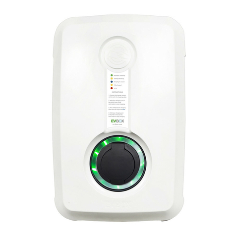
Components & features
Charging cable
The charging cable is compat-
ible with all types of electric
vehicles with type 2 charging
plug that can handle capaci-
ties for 7.4 kW or 11 kW.
Card/key fob reader
This is the area where you
scan your charge card or
key fob for WALL BOX with
activated RFID card/keyfob
or SMART wall boxes. The
wall box reads the data from
your card to start or stop a
charging session.
Operating system
Start and stop your
charging session ac-
cording to your wall box
model:
WALL BOX:
Plug your charging
cable into the car to start
charging.
WALL BOX with activated
RFID card/ keyfob:
Plug your charging cable
into the car and hold your
RFID card/key fob in front
of RFID reader to start
charging.
SMART WALL BOX:
Equipped with Wi-Fi,
UMTS and kWh meter.
Plug your charging cable
into the car and hold your
RFID card/key fob in front
of RFID reader to start
charging and track your
sessions online.
1
2
2
3
3
4
4
5
5
Housing
The wall box consists of a
wall dock, a wall box and a
charging cable.
The wall box is designed with
rugged, high-impact strength
plastics that make its housing
durable, robust, weather-resis-
tant and wear-resistant.
LED indicator.
This smart status indicator
helps you understand what
the wall box is doing at all
times.
EN
Product Classication
• EV Supply Equipment connected to AC supply network
• Electric connection method: permanently connected
• AC EV Supply Equipment
• Outdoor use
• Equipment for locations with non-restricted access
• Stationary equipment, mounted on walls, poles or equiva-
lent means: surface mounted
• Class I Equipment
• Mode 3 EVSE
• Operating temperature range: -25°C to 45°C
• Enclosure ratings: IP55, IK10
INSTALLATION_WALL_BOX_PSA_B2C_MERGED.indd 8 11-9-2019 8:30:42
Part number: 9835662780

9
Components
Wall dock Wall Box
Keys
Charging
cable
Charging plug
Type 2
Dimensions (in mm)
EN
161 184
328
INSTALLATION_WALL_BOX_PSA_B2C_MERGED.indd 9 11-9-2019 8:30:42
Part number: 9835662780

10
1. Unpack wall box
1.1
Place the wall box package on a at and stable
surface.
Remove sleeve.
1.2
Set the boxes aside.
Box 1 contains the wall box.
Box 2 contains the charging cable.
1.3
Open the wall box package.
Put the cardboard folder (A) aside.
The keys (B) found in this folder are only needed
for removing the wall box (C) from its wall dock
(D) in case of maintenance.
Note: After installation, hand over the cardboard
folder to the user, as it also contains the charge
card (E), the key fob (F) and wall box ID + security
code (G).
1.4
Take out the wall box together with its cardboard
buffer from its box.
1.5
Take out the wall dock from its box.
A
D
C
EN
B
E
F
G
INSTALLATION_WALL_BOX_PSA_B2C_MERGED.indd 10 11-9-2019 8:30:53
Part number: 9835662780

11
EN
Warning: Risk of electric shock.
Before installing the wall dock, make sure that the power line you’re using is
switched off on your service panel.
Make sure that the power line to the wall box is installed on a dedicated circuit
breaker (MCB) on your service panel. The installation must incorporate an adequate
residual-current device (RCD). The MCB must be in line with the capacity of the
charging cable. In case the amperage rating of the charging cable is different than
the amperage rating of the (MCB), the installer/user must change the wall box
settings in the EVBox Connect App.
Be aware that local regulations may be applicable and may vary depending on your
region/country of residence. The installing party must always ensure that the wall
box is installed according to the local regulations.
The installation settings of your service panel must always be adjusted by a qualied
electrician.
8 mm
drill bit
drill
knife
4x screw
5 x 70 mm 4x plug
8 x 65 mm
1x bit T25
1x bit T30
at-head
screwdriver
2. Install wall dock
Tools you need to install the wall dock
Included
in the box Not included
in the box
rubber seal strain relief
bubble
level
bit-holding
screwdriver
1x bit T20
sleeve with
drilling template
mobile
device
INSTALLATION_WALL_BOX_PSA_B2C_MERGED.indd 11 11-9-2019 8:30:56
Part number: 9835662780

12
2. Install wall dock
Installation advice
Ground connection
advice
TN-system PE-cable
TT-system
IT-system Earth electrode installed separately (self-in-
stalled)
Input 1-phase 230 V ±10% 50/60 Hz
3-phase 400 V ± 10% 50/60 Hz
MCB C-characteristic (MCB must be selected to match the amper-
age settings of the wall box, considering MCB manufacturer
specications)
RCD 40 A, 30 mA AC type A
Note: In case of a TT or IT electric grid with 230 V from line to line, the wall box must be
installed with 1-phase by connecting the clamps on L1 and N.
Service wiring
Option1:
400 V 3-phase with neutral
For 3-phase use of a Wye-connected secondary,
all three phases (L1, L2 and L3) and neutral must
be connected. Each phase voltage must measure
230 V to neutral.
L1
L2
L3
N
G
230 V
230 V
230 V
400 V
EN
INSTALLATION_WALL_BOX_PSA_B2C_MERGED.indd 12 11-9-2019 8:30:58
Part number: 9835662780

13
EN
Option 2:
230 V 1-phase with neutral
For 1-phase use of a Wye-connected secondary, only
a single phase (L1) and neutral must be connected.
This phase voltage must measure 230 V between line
and neutral.
Warning: In this conguration, the wall box operates
only from a single phase (L1). Do not connect the
remaining phases L2 and L3.
Option 3:
230 V 1-phase without neutral
In this conguration (without a neutral and 230 V
from line to line), connect any two lines (L1, L2 or L3)
to the L1 and neutral positions on the terminal block
of the wall box.
L1
L2
L3
N
G
230 V
230 V
L1
L2
L3
N
G
230 V
2. Install wall dock
INSTALLATION_WALL_BOX_PSA_B2C_MERGED.indd 13 11-9-2019 8:30:58
Part number: 9835662780

14
2. Install wall dock
2.1
Select a solid and at vertical surface for installing
the wall dock.
Ensure that the surface is even and solid enough to
resist a pull force of at least 100 kg.
2.2
Find the drilling template at the bottom of the box’s
sleeve. Cut the drilling template out from the sleeve.
2.3
Place the drilling template onto the wall and use a
level device (e.g. bubble level) to align the template.
Mark the 4 mounting points on the wall and remove
the template.
2.4
Drill holes with a drill round of 8 mm.
Use the provided 8x65 mm plugs.
2.5
Remove the protective rubber cap.
Undo the 4 corner screws (3x Torx T20 using the
supplied T20 bit and 1x slotted using a regular at-
head screwdriver).
Remove the transparent cover from the wall dock.
2.6
Mount the wall dock onto the wall.
Use the provided 5x70 mm screws. Use the supplied
Torx T25 bit to fasten the screws.
EN
INSTALLATION_WALL_BOX_PSA_B2C_MERGED.indd 14 11-9-2019 8:31:09
Part number: 9835662780

15
EN
2. Install wall dock
x mm
2.7
Measure the power cable’s diameter and cut out the
correct diameter of the rubber seal in order to allow the
power cable to get through.
Note: Strain relief and rubber seal are supplied in a
separate bag in the box.
2.8
Feed the power line through the rubber seal.
The total length of the power line fed through the rubber
seal must be 180 mm.
Strip the power line over a length of 130 mm.
In case of stranded (exible) wiring, use wire end sleeves
with a ferrule length of 12-15 mm and apply a square
crimp for optimal t into the connection terminals.
2.9
Assemble the strain relief.
Depending on the feed wire’s thickness, use either the
small or large diameter on the strain relief. Simply ip
the symmetrical parts to obtain a different strain relief
diameter.
Small Large
Power line cable
INSTALLATION_WALL_BOX_PSA_B2C_MERGED.indd 15 11-9-2019 8:31:09
Part number: 9835662780

16
2. Install wall dock
2.10
Place one part of the strain relief in the bottom of the wall dock.
Place the feed wire over the bottom part of the strain relief and mount the rubber seal in the
outer edge of the wall dock.
Note: Be aware that the rubber seal has three groove edges and one tongue edge. Make sure
that you place the tongue edge facing upwards.
Place the top part of the strain relief over the feed wire and use the two 4 x 40 mm screws and
the Torx T20 head to mount the strain relief on the feed wire. Do not overtighten.
PE N L1 L2 L3
2.11
Connect the wires in their designated terminals. Mount the transparent cover.
Make sure no wiring is protruding from under the transparent cover.
Make sure that the rubber seal gasket around the connectors is in place before assembling the
transparent cover.
Tighten the bolts with the T20 bit. Do not overtighten.
Fasten the special bolt in the bottom right corner with a regular at-head screw driver. This
special bolt can be used for sealing the installation with a tamper-evident seal.
Note: Installation example of a 1-phase connection of wall box.
EN
INSTALLATION_WALL_BOX_PSA_B2C_MERGED.indd 16 11-9-2019 8:31:25
Part number: 9835662780
17
EN
3. Install charging cable
3.1
Unpack the charging cable box.
Remove the cardboard cover from the wall box’s socket.
3.2
Take the charging cable out of the box.
Check that the rubber sealing ring on the charging plug is
in place and not twisted. This is to ensure that the proper IP
code (protection class) is met.
Place the wall box on its side and then plug the charging
cable into the wall box.
Tools you need to install the charging cable
3.3
Make sure you press the charging cable until it is rmly
secured.
3.4
Turn the wall box around and put the front face of the wall
box on a soft surface. Place the bolt and rmly tighten the
bolt with the T30 bit.
Reconrm that the cable bolt is tightened properly.
Check again that the charging cable is rmly connected to
the wall box.
1x bit T30
INSTALLATION_WALL_BOX_PSA_B2C_MERGED.indd 17 11-9-2019 8:31:26
Part number: 9835662780

18
EN
4. Install wall box
Before mounting, write down the ID of your wall box.
This can be found on the backside of the wall box and in the
cardboard folder containing the RFID card and key fob.
5.1
Align the wall box against the wall dock and press it in a straight
line until you hear a clicking sound.
To ensure that the connection is fully secured, press rmly on all
four corners and check that there is no air gap between the wall
dock and the wall box.
5.2
Tools you need to install the wall box
No specic tools needed for this step.
WALL BOX
SMART
WALL BOX
Switch on the power to the wall box on the
service panel. The wall box will switch on
automatically. This is indicated by a ashing
red LED ring.
Do not turn on the power to the wall box
before wall box activation.
Give the cardboard folder to the user and
ask them to activate the wall box.
INSTALLATION_WALL_BOX_PSA_B2C_MERGED.indd 18 11-9-2019 8:31:32
Part number: 9835662780

19
EN
5. Activate wall box
Note: You can use your smart wall box also without RFID card/key fob.
For regular wall box models, the activation of the wall box is not applicable.
The EVBox Connect App is designed for both installers and users and to adjust the wall box settings
(e.g. setting of maximum amperage or adding/activating RFID cards/key fobs).
To nd out more about the App features, please refer to the EVBox Connect App manual.
The Smart Wall Box App is a management App for electric vehicle charging stations.
The App allows both charging station owners and electric vehicle drivers to easily start/stop, track
and invoice charging sessions. It also enables station owners to take full control over the energy
consumption of their charging stations.
For more information about the App features, please refer to the Smart Wall Box App manual.
Please refer to the table on next page for the step-by-step instructions for both Apps.
Please refer to ifz-berlin.de/#/instructions for the latest manuals.
Tools you need to activate the wall box
EVBox Connect App
Smart Wall Box App*
*Applicable for Smart Wall Box only
INSTALLATION_WALL_BOX_PSA_B2C_MERGED.indd 19 11-9-2019 8:31:34
Part number: 9835662780

20
EN
Wallbox
Descrip-
tion/
reference
number
WALL BOX 7,4 kW S / 9835663080 SMART WALL BOX 22 kW S /
9835662680*
(factory setting)
non active RFID
(factory setting) active RFID
(user setting)
Activation Not applicable 1. Turn on the power to the
wall box.
2. Download the EVBox
Connect App.
3. Enable Buetooth on your
mobile device. Pair the wall
box with a mobile device
via Bluetooth.
4. Add a charge card or key
fob by entering its ID into
the EVBox Connect App
under “Cards” menu.
Note: You can nd the wall
box ID and security code on
the label inside the cardboard
folder. The charge card and
key fob are also located in the
cardboard folder.
1. Make sure that the power to the
wall box is off.
2. The user to download the Smart
Wall Box App.
3. The user to set up an user
account for the wall box to be
installed in the back-end.
4. The user to register the wall box
in the Smart Wall Box Backend
using the wall box ID (EVB-
PXXXXXXXX).
5. The user to register the charge
card/key fob using the contract
ID (NL-EVB-XXXXXXXX) in the
Smart Wall Box Backend.
6. Turn on the power to the wall
box.
Congura-
tion Not applicable Select the option “Charge
using charging card“ under
“charging settings” menu in
the EVBox Connect App.
Note: Select the option
“Autostart“ under “charging
settings” menu in the EVBox
Connect App. in order to
disable/enable the charging
card usage.
For more information, please refer
to the Smart Wall Box App manual.
Charging Start charging:
• Plug in the
charging cable
on the EV side
Stop charging:
• Unplug the
charging cable
on the EV side
Refer to the vehicle’s
user manual
Note: RFID reader is
not active.
Note: Charging
sessions are not
logged.
Start charging:
• Plug in the charging cable
on the EV side
• Scan your charge card/
key fob
Stop charging:
• Scan your charge card/
key fob
• Unplug the charging cable
on the EV side
Note: RFID reader is active.
Note: Charging sessions are
not logged.
Start charging:
• Plug in the charging cable on
the EV side
• Scan your charge card/key fob
Stop charging:
• Scan your charge card/key fob
• Unplug the charging cable on
the EV side
Note: RFID reader is active.
Note: Charging sessions are
logged.
*The SMART WALL BOX can be congured as a standard WALL BOX using the EVBox Connect App.
INSTALLATION_WALL_BOX_PSA_B2C_MERGED.indd 20 11-9-2019 8:31:34
Part number: 9835662780

21
EN
6. Troubleshooting
What you see What it means What to do
LED ring off
or green Wall box is ready for use. Plug the charging cable into the wall box.
LED ring
green, ashing
Your charge card is being
veried.
Wait until LED ring turns blue.
LED ring
yellow The car is fully charged. Unplug the charging cable on the EV side.
Refer to the vehicle’s user manual.
LED ring
yellow, ashing
Charging session is in queue
(applicable in the Smart
Charging environment only).
When power becomes available, charging will
start or resume, and the LED ring will turn blue.
LED ring
blue Wall box is charging the car. The car is charging.
LED ring
red Wall box is experiencing
an error. Check the troubleshooting chapter in this man-
ual for solutions. If this does not solve the issue,
contact your installer or supplier.
LED ring
red, ashing
Your charge card is not
authorized to charge. Check the troubleshooting chapter in this man-
ual for solutions. If this does not solve the issue,
contact your installer or supplier.
LED ring
purple, ashing
The wall box identies itself
to the user during the blue-
tooth pairing process
Continue the bluetooth pairing process.
Led ring status
Wallbox
Descrip-
tion/
reference
number
WALL BOX 7,4 kW S / 9835663080 SMART WALL BOX 22 kW S /
9835662680*
(factory setting)
non active RFID
(factory setting) active RFID
(user setting)
Activation Not applicable 1. Turn on the power to the
wall box.
2. Download the EVBox
Connect App.
3. Enable Buetooth on your
mobile device. Pair the wall
box with a mobile device
via Bluetooth.
4. Add a charge card or key
fob by entering its ID into
the EVBox Connect App
under “Cards” menu.
Note: You can nd the wall
box ID and security code on
the label inside the cardboard
folder. The charge card and
key fob are also located in the
cardboard folder.
1. Make sure that the power to the
wall box is off.
2. The user to download the Smart
Wall Box App.
3. The user to set up an user
account for the wall box to be
installed in the back-end.
4. The user to register the wall box
in the Smart Wall Box Backend
using the wall box ID (EVB-
PXXXXXXXX).
5. The user to register the charge
card/key fob using the contract
ID (NL-EVB-XXXXXXXX) in the
Smart Wall Box Backend.
6. Turn on the power to the wall
box.
Congura-
tion Not applicable Select the option “Charge
using charging card“ under
“charging settings” menu in
the EVBox Connect App.
Note: Select the option
“Autostart“ under “charging
settings” menu in the EVBox
Connect App. in order to
disable/enable the charging
card usage.
For more information, please refer
to the Smart Wall Box App manual.
Charging Start charging:
• Plug in the
charging cable
on the EV side
Stop charging:
• Unplug the
charging cable
on the EV side
Refer to the vehicle’s
user manual
Note: RFID reader is
not active.
Note: Charging
sessions are not
logged.
Start charging:
• Plug in the charging cable
on the EV side
• Scan your charge card/
key fob
Stop charging:
• Scan your charge card/
key fob
• Unplug the charging cable
on the EV side
Note: RFID reader is active.
Note: Charging sessions are
not logged.
Start charging:
• Plug in the charging cable on
the EV side
• Scan your charge card/key fob
Stop charging:
• Scan your charge card/key fob
• Unplug the charging cable on
the EV side
Note: RFID reader is active.
Note: Charging sessions are
logged.
*The SMART WALL BOX can be congured as a standard WALL BOX using the EVBox Connect App.
INSTALLATION_WALL_BOX_PSA_B2C_MERGED.indd 21 11-9-2019 8:31:34
Part number: 9835662780
Table of contents
Languages:
Other EVBox Batteries Charger manuals

EVBox
EVBox BusinessLine User manual

EVBox
EVBox Elvi User manual

EVBox
EVBox Smart Charging User manual

EVBox
EVBox BusinessLine User manual

EVBox
EVBox BusinessLine User manual

EVBox
EVBox 9835662680 User manual

EVBox
EVBox BusinessLine User manual

EVBox
EVBox HomeLine User manual

EVBox
EVBox HomeLine User manual

EVBox
EVBox Elvi V3.3 E3320-A555X-10.3 User manual

EVBox
EVBox 9835662680 User manual

EVBox
EVBox Elvi User manual

EVBox
EVBox Elvi User manual

EVBox
EVBox Iqon Guide

EVBox
EVBox Elvi User manual

EVBox
EVBox Elvi User manual

EVBox
EVBox BusinessLine series User manual

EVBox
EVBox Wall box Series User manual

EVBox
EVBox Elvi User manual

EVBox
EVBox BusinessLine User manual