EVBox Elvi User manual

1
Installation manual
Elvi

2
I’m home!
Let’s get started.

3
Installation manual
Elvi

4
Contents
Contents 4
Safety precautions 5
Components & features 6
1. Unpack Elvi 8
2. Install wall dock 10
3. Install charging cable 16
4. Activate Elvi 17
5. Install station 18
6. Install cable dock 19
7. Change charging cable 21
8. Charge with Elvi 23
9. Troubleshooting 24
10. Warranty 26
11. Declaration of conformity 27
EN

5
Warning: Risk of electric shock.
• Read the supplied documentation carefully to familiarize yourself with all safety
instructions and regulations before using this product.
• This product is designed and tested in accordance with international standards.
• The use of this product is limited to those applications it is designed for.
• Installation, maintenance and repairs of this product are only to be performed by
qualied personnel.
• Incorrect installation or repairs may cause hazardous situations for the user of this
product.
• This product is used in combination with a power source.
• Always switch off power before any maintenance activity.
• This product contains no user-serviceable parts. Consult EVBox or your
distributor for more information. Do not attempt to service or repair the charging
station yourself!
• Make sure that the product is only used under the correct operating conditions.
• Make sure that the main power is disconnected before storing or transporting
this product.
• Make sure that the power line to Elvi is installed on a dedicated circuit breaker
(MCB) on your service panel. The installation must incorporate an adequate
residual-current device (RCD). The MCB must be in line with the capacity of the
charging cable (3.7, 7.4, 11, 22 kW). In case the amperage rating of the charging
cable is different than the amperage rating of the (MCB), the installer/user must
change the station settings in the mobile app and/or web platform for station
management as provided by the operator or service provider for this product.
The installing party must always ensure that the charging station is installed according
to the local regulations. The installation settings of the service panel must always be
adjusted by a qualied electrician.
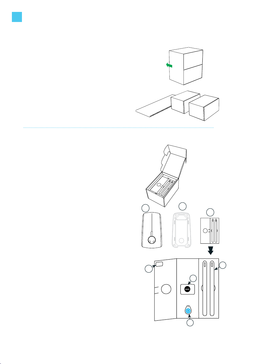
EVBox is not responsible for any damage that occurs if this product is transported in a
different packaging than the packaging in which the product was originally supplied.
Store this product in a dry environment; the storage temperature must
be between -25 °C and +60 °C.
EVBox strives to manufacture products of the highest quality. EVBox products
bear the CE certication and are compliant with the essential requirements of
EMC Directive 2014/30/EU and Low Voltage Directive 2014/35/EU.
More details can be found at evbox.com or in this installation manual.
EVBox products are sold with a limited warranty described at
evbox.com/general-terms-conditions.
Safety precautions
EN

6
Components & features
Charging cable & cable dock
The Elvi charging cable is
compatible with all types
of electric vehicles that can
handle capacities from 3.7 kW
up to 22 kW.
The cable dock (sold sepa-
rately, part. No. 290135) se-
cures the cable in its position
when Elvi is not in use.
Note: Make sure to select a
charging cable/plug that is
compatible with your car.
Card reader
This is the area where you
scan your charge card or key
fob. Elvi reads the data from
your card to start or stop a
charging session.
Operating system
Elvi is connected via a
built-in dual band Wi-Fi
connection or via an option-
al UMTS-modem.
Start and stop your charging
session with your charge
card, key fob or remotely
via the app.
1
12
2
3
3
4
4
5
5
Housing
Elvi consists of a wall dock,
a charging station and a
charging cable.
Elvi is designed with rugged,
high-impact strength plastics
that make its housing durable,
robust, weather-resistant and
wear-resistant.
LED indicator
EVBox is the innovator
behind the LED ring.
This smart status indicator
helps you understand what
Elvi is doing at all times.
EN

7
Components
Cable dock
(sold separately)
Cable dock
(sold separately)
Wall dock Station
Keys
Charging
cable
Cable dock
Wall base
Cable dock
Plug holder
for Type 2
Charging
plug
Cable dock
Plug holder
for Type 1
Charging
plug
Cable dock
Front cover
Charging plug
(Type 2 in
example)
Dimensions (in mm)
161 184
328
94 122
197
EN

8
1. Unpack Elvi
1.1
Place Elvi package on a at and stable surface.
Remove sleeve.
1.2
Set the boxes aside.
Box 1 contains the charging station.
Box 2 contains the charging cable.
1.3
Open the charging station box.
Put the instructions folder (A) aside.
The keys (B) found in this folder are only needed
for removing the charging station (C) from its wall
dock (D) (in case of maintenance or to change the
charging cable).
Note: After installation, hand over the folder to
the user, as it also contains the charge card (E),
the key fob (F) and station ID + security code (G).
1.4
Take out the charging station together with its
cardboard buffer from its box.
1.5
Take out the wall dock from its box.
Skip this step if the wall dock is already installed.
(In this case, the wall dock is not included in the
box.)
A
D
C
B
E
F
G
EN

9
1. Unpack Elvi
Wall dock
already installed? Go to next page
Go to page 13
YES
NO
EN

10
Warning: Risk of electric shock.
Before installing the wall dock, make sure that the power line you’re using is
switched off on your service panel.
Make sure that the power line to Elvi is installed on a dedicated circuit breaker
(MCB) on your service panel. The installation must incorporate an adequate residual-
current device (RCD). The MCB must be in line with the capacity of the charging
cable (3.7, 7.4, 11, 22 kW). In case the amperage rating of the charging cable is
different than the amperage rating of the (MCB), the installer/user must change the
station settings in the mobile app and/or web platform for station management as
provided by the operator or service provider for this product.
Be aware that local regulations may be applicable and may vary depending on your
region/country of residence. The installing party must always ensure that the station
is installed according to the local regulations.
The installation settings of your service panel must always be adjusted by a qualied
electrician.
8 mm
drill bit
drill
knife
4x screw
5 x 70 mm
4x plug
8 x 65 mm
1x bit T25
1x bit T30
at-head
screwdriver
2. Install wall dock
Tools you need to install the wall dock
Included
in the box
Not included
in the box
rubber seal strain relief
bubble
level
bit-holding
screwdriver
1x bit T20
sleeve with
drilling template
EN

11
2. Install wall dock
Installation advice
Ground connection
advice
TN-system PE-cable
TT-system
IT-system
Earth electrode installed separately (self-in-
stalled)
Input 1-phase 230 V ±10% 50/60 Hz
3-phase 400 V ± 10% 50/60 Hz
MCB C-characteristic (MCB must be selected to match the am-
perage settings of the charging station, considering MCB
manufacturer specications)
RCD 40 A, 30 mA AC type A
Note for the installer: In case of a TT or IT electric grid with 230 V from line to line, Elvi
must be installed with 1-phase by connecting the clamps on L1 and N.
Service wiring
Option1:
400 V 3-phase with neutral
For 3-phase use of a Wye-connected secondary,
all three phases (L1, L2 and L3) and neutral must
be connected. Each phase voltage must measure
230 V to neutral.
EN
L1
L2
L3
N
G
230V
230V
230V
400V

12
Option 2:
230 V 1-phase with neutral
For 1-phase use of a Wye-connected secondary, only
a single phase (L1) and neutral must be connected.
This phase voltage must measure 230 V between line
and neutral.
Warning: In this conguration, the charging station
operates only from a single phase (L1). Do not
connect the remaining phases L2 and L3.
Option 3:
230 V 1-phase without neutral
In this conguration (without a neutral and 230 V
from line to line), connect any two lines (L1, L2 or L3)
to the L1 and neutral positions on the terminal block
of the charging station.
Note: In case you are not sure about the available
connection type at the service panel, consult a
qualied electrician.
L1
L2
L3
N
G
230 V
230 V
L1
L2
L3
N
G
230 V
2. Install wall dock
EN

13
2. Install wall dock
2.1
Select a solid and at vertical surface for installing
the wall dock.
Ensure that the surface is even and solid enough to
resist a pull force of at least 100 kg.
2.2
Find the drilling template at the bottom of the box’s
sleeve. Cut the drilling template out from the sleeve.
2.3
Place the drilling template onto the wall and use a
level device (e.g. bubble level) to align the template.
Mark the 4 mounting points on the wall and remove
the template.
2.4
Drill holes with a drill round of 8 mm.
Use the provided 8x65 mm plugs.
2.5
Remove the transparent cover from the wall dock
by undoing the 4 corner screws (3x Torx T20 using
the supplied T20 bit and 1x slotted using a regular
at-head screwdriver).
2.6
Mount the wall dock onto the wall.
Use the provided 5x70 mm screws. Use the supplied
Torx T25 bit to fasten the screws.
EN

14
2. Install wall dock
x mm
2.7
Measure the power cable’s diameter and cut out the
correct diameter of the rubber seal in order to allow the
power cable and optional data cables to get through.
Note: Strain relief and rubber seal are supplied in a
separate bag in the box.
2.8
Feed the power line and optional data wiring through the
rubber seal.
The total length of the power line fed through the rubber
seal must be 180 mm.
Strip the power line over a length of 130 mm.
In case of stranded (exible) wiring, use wire end sleeves
with a ferrule length of 12-15 mm and apply a square
crimp for optimal t into the connection terminals.
2.9
Assemble the strain relief.
Depending on the feed wire’s thickness, use either the
small or large diameter on the strain relief. Simply ip
the symmetrical parts to obtain a different strain relief
diameter.
The strain relief also accommodates
for extra data cables on two sides
(e.g. UTP/CAT5E/CAT6).
Small Large
Optional data cable
Optional data cable
Power line cable
EN

15
2. Install wall dock
2.10
Place one part of the strain relief in the bottom of the wall dock.
Place the feed wire over the bottom part of the strain relief and mount the rubber seal in the
outer edge of the wall dock.
Note: Be aware that the rubber seal has three groove edges and one tongue edge. Make sure
that you place the tongue edge facing upwards.
Place the top part of the strain relief over the feed wire and use the two 4 x 40 mm screws and
the Torx T20 head to mount the strain relief on the feed wire. Do not overtighten.
PE N L1 L2 L3
2.11
Connect the wires in their designated terminals. Mount the transparent cover.
Make sure no wiring is protruding from under the transparent cover.
Make sure that the rubber seal gasket around the connectors is in place before assembling the
transparent cover.
Tighten the bolts with the T20 bit. Do not overtighten.
Fasten the special bolt in the bottom right corner with a regular at-head screw driver. This
special bolt can be used for sealing the installation with a tamper-evident seal.
Note: Installation example of a 1-phase connection of Elvi.
EN

16
3. Install charging cable
3.1
Unpack the charging cable box.
Remove the cardboard cover from the station’s socket.
3.2
Take the charging cable out of the box.
Check that the rubber sealing ring on the charging plug is
in place and not twisted. This is to ensure that the proper IP
code (protection class) is met.
Place the charging station on its side and then plug the
charging cable into the station.
Tools you need to install the charging cable
3.3
Make sure you press the charging cable until it is rmly
secured.
3.4
Turn the station around and put the front face of the station
on a soft surface. Place the bolt and rmly tighten the bolt
with the T30 bit.
Reconrm that the cable bolt is tightened properly.
Check again that the charging cable is rmly connected to
the station.
1x bit T30
EN

17
4. Activate Elvi
4.1
Download the mobile app for station management from your app store.
The app is available on both Android and iOS.
4.2
Log in to your account in the app.
If you don’t have an account yet, create a new account in the app.
Register Elvi in the app by adding its station ID and security code.
Find the station ID on the back of your Elvi or in the supplied instructions folder inside the Elvi
box.
Find the security code in the supplied instructions folder inside the Elvi box.
Find the charge card in the supplied instructions folder inside the Elvi box.
4.3
Follow the steps in the app to connect Elvi.
Note: The charging station operates with a Wi-Fi or cellular connection. Elvi will always search
for Wi-Fi but it will choose the cellular connection when Wi-Fi is not found.
4.4
Activate your charge card in the mobile app for station management.
If you have a key fob, this needs to be registered separately from your charge card in the app.
Your charge card and key fob have separate ID numbers.
Your charge card/key fob tracks and registers all your charging sessions in your mobile app for
station management and/or backend portal account as provided by the operator or service
provider of this product.
Need more help?
If you need assistance with setting up Elvi, your mobile station management application and/
or backend portal account, please contact your operator or service provider of this product for
further support.
Start Stop
EN

18
5. Install station
Before mounting, write down the Elvi station ID.
This can be found on the backside of the station.
5.1
Align the station against the wall dock and press it in a straight
line until you hear a clicking sound.
To ensure that the connection is fully secured, press rmly on all
four corners and check that there is no air gap between the wall
dock and the station.
5.2
Switch on the power to the station on the service panel. Elvi will
switch on automatically. This is indicated by a ashing red LED
ring.
Note: If the LED ring does not show any color, it may be due to
improper installation of the charging cable. In this case, check/
repeat steps 3.3 and 3.4.
Note: Please be aware that soon after its registration and
activation, Elvi might start a software update automatically. Do
not switch Elvi off.
If the LED ring will not turn green after 20 minutes, verify that
the station is online in the backend/portal account. If the station
is not online, please contact your operator or service provider
for this product
Tools you need to install the station
No specic tools needed for this step.
CLICK
EN

19
~ W 300 mm
H 65 mm
6. Install cable dock
sold separately
The Elvi cable dock is sold separately,
part No. 290135.
6.1
Unpack your Elvi cable dock.
Disassemble the charging cable holder by
removing the Torx bolt with the T30 bit.
6.2
Place the cable dock’s wall base on a solid and
at surface. Position the cable dock on the wall as
illustrated (it should be to the side of your station
and at a comfortable height within at least 1
meter from the ground).
Use the cable dock’s wall base as a drilling
template to mark the 3 holes to be drilled.
Make sure it is level.
6.3
Drill holes with drill round 8 mm.
Use the supplied plugs 8 x 65 mm.
Tools you need to install the cable dock
8 mm
drill bit
drill
pencil
3x
screw 5 x 70mm
3x
plug 8 x 65mm
Included
in the box
Not
included
in the box
1x bit T30 bit-holding
screwdriver
1x bit T25
EN

20
6. Install cable dock
6.4
Place the cable dock’s wall base on the wall and fasten
the three screws 5 x 70 mm length.
Do not overtighten.
6.5
The Elvi cable dock is supplied with two plug holder
options: one for Type 1 and one for Type 2 charging
plugs.
Choose the plug holder that corresponds to your
charging cable and insert it into the cable dock.
Fasten the bolt with the T30 bit. Do not overtighten.
Success!
You’re all set.
EN
Other manuals for Elvi
9
Table of contents
Other EVBox Batteries Charger manuals

EVBox
EVBox Iqon Guide

EVBox
EVBox Elvi User manual

EVBox
EVBox BusinessLine User manual

EVBox
EVBox Elvi User manual

EVBox
EVBox BusinessLine User manual

EVBox
EVBox Elvi V3.3 E3320-A555X-10.3 User manual

EVBox
EVBox HomeLine User manual

EVBox
EVBox Elvi User manual

EVBox
EVBox BusinessLine User manual

EVBox
EVBox Elvi User manual

EVBox
EVBox HomeLine User manual

EVBox
EVBox Smart Charging User manual

EVBox
EVBox Elvi User manual

EVBox
EVBox 9835662780 User manual

EVBox
EVBox Iqon Guide

EVBox
EVBox BusinessLine series User manual

EVBox
EVBox Elvi User manual

EVBox
EVBox 9835662680 User manual

EVBox
EVBox Troniq User manual

EVBox
EVBox Wall box Series User manual