EVBox BusinessLine User manual

Installation manual
BusinessLine

I’m home!
Let’s get started.

Installation manual
BusinessLine
EN

4
EN
Contents
General 5
1. Safety regulations 6
Safety warnings 6
Transport and storage 7
Maintenance 7
2. What’s inside 8
3. Product features 9
About BusinessLine 9
Online BusinessLine (model with communication module) 9
1. Mode 3 controller 9
2. RFID reader 9
3. LED status indicator 9
4. Technical specications 10
4.1 Specications overview 10
4.2 Charge box 11
5. Product type guide 12
6. Install station 13
6.1 Safety requirements 13
Planning the installation 13
6.2 Open cover(s) 14
6.3 Choose location 14
6.4 Run power supply cables 14
6.5 Connector capacities 15
6.6 Attach power supply cable 16
6.7 Connect station 16
6.8 Mount station 18
6.9 Finish installation 19
7. Install communication module externally 20
8. Congure Hub-Satellite 21
8.1 How does it work? 21
8.2 Power conguration 21
8.3 Attach data cables 22
8.4 Consult phase rotation diagram 24
9. Operate station 25
9.1 Charge with RFID card 25
9.2 Charge without RFID card 25
9.3 LED status indicator chart 26
10. Troubleshooting 27
11. Warranty 29
12. Declaration of conformity 30

5
General
Errors or inaccuracies
For any inaccuracies or omissions, or to provide feedback and suggestions,
send an email to [email protected].
Product and environmental characteristics
The charging station has been CE-certied by the manufacturer and bears
the CE logo. The relevant declaration of conformity may be obtained from
the manufacturer. The charging station complies with the RoHS Directive
(RL 2011/65/EU). The relevant declaration of conformity may be obtained
from the manufacturer. Electrical and electronic appliances, including
accessories, must be disposed of separately from the general municipal
solid waste. Recycling of materials saves raw materials and energy and
makes a major contribution to conserving the environment.
EN

6
1. Safety regulations
Safety warnings
Warning: Risk of electric shock
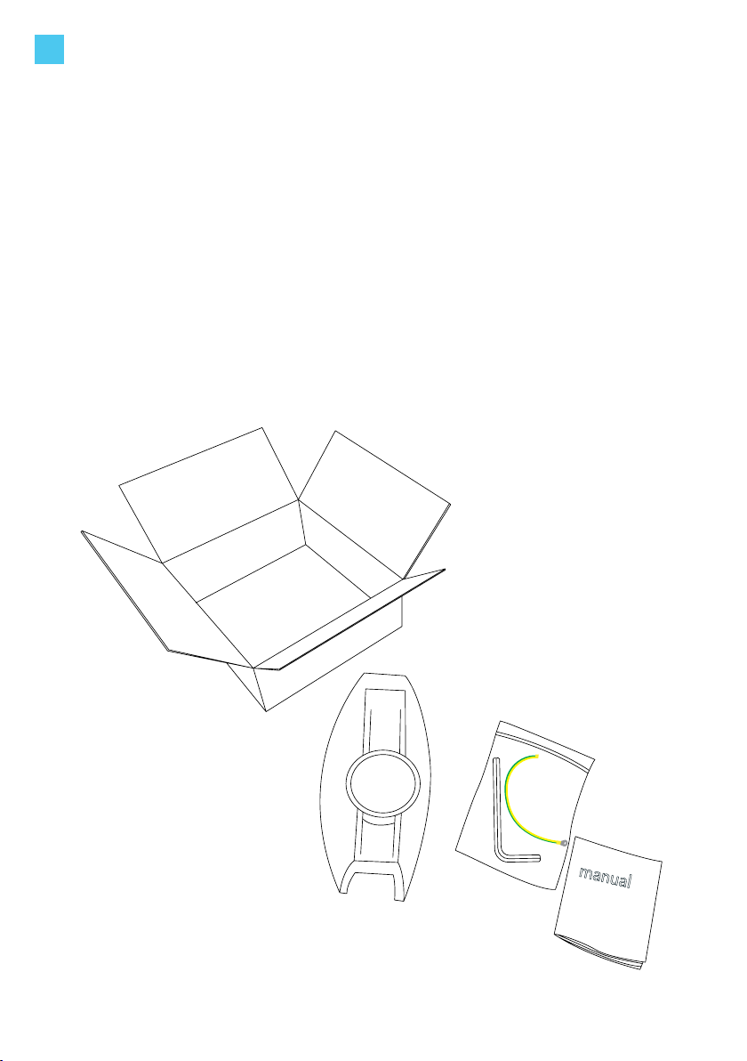
• Please read the documentation provided with the charging station to acquaint yourself with the
safety instructions and directions before installing or using the charging station.
• In the event of danger and/or accidents, have the charging station disconnected immediately by a
certied electrician.
• Do not operate the charging station if it is physically damaged or if the charging cable shows signs
of cracks, excessive wear, or other visible damage. Contact EVBox or your distributor for more
information.
• Do not direct powerful jets of water toward or onto the charging station. Never operate it with wet
hands. Do not put the EV plug into any liquid.
• Please carefully read our instructions and the vehicle’s operating instructions in your owners
manual before charging your electric vehicle.
• Failure to follow these guidelines may result in serious injury or even death.
Warning: Turn off input power to your charging station at the circuit breaker panel before installing,
maintaining or servicing the unit. Make sure that the input power stays off until the cover is in the
correct position.
Cautions
• Use this charging station for charging all Mode 3 compatible electric vehicles only. Refer to your
vehicle owner’s manual to make sure that your vehicle is compatible.
• This product may impact the operation of implanted electronic medical devices. Consult with the
supplier of the electronic medical device if its operation can be inuenced by charging effects
before operating the charging station.
• This charging station may only be installed, maintained, and repaired by qualied personnel.
Incompetent installation or repairs may result in danger to the user and could result in a voided
warranty.
• This product contains no user serviceable parts. Consult EVBox or your distributor for more
information. Please do not attempt to service or repair the charging station yourself.
• Do not install a defective charging station or a station with an obvious problem. For instructions
on installation, refer to chapter “6. Install station”.
• Make sure that the charging cable cannot come into contact with heat sources.
• Make sure that the product is only used under the correct operating conditions (refer to chapter
“4. Technical specications”).
• Do not use explosives or readily ammable substances in the vicinity of the charging station.
• Persons unable to estimate the dangers involved in operating a charging station should not use
the charging station.
• Do not allow children to operate this device. Adult supervision is required when children are in the
proximity of a charging station that is in use.
• Make sure that the charging cable is positioned so that it will not be stepped on, tripped or driven
over, or otherwise subjected to excessive force or damage.
• Make sure that the charging cable is not kinked or jammed.
• While charging, the cable must be completely unwound and connected to the vehicle without
overlapping loops (this is to avoid the risk of the charging cable from overheating).
• Always pull on the plug’s hand grip, never on the charging cable itself.
• Do not put ngers or other objects inside the charging port or plug port.
• Do not switch on the charging station if the covers are not in place.
EN

7
1. Safety regulations
Remarks
• This product is designed and tested in accordance with international standards.
• All components were correctly connected and operationally tested before dispatch of the
charging station.
• The use of this product is limited to those applications it is designed for.
• These instructions are valid for several models of the charging station. It is possible that some
features and options described herein may not apply to your charging station.
• The charging station complies with Safety Class I (ground terminal safety) and Category III
(overvoltage).
• Do not modify the charging station in any way. This will result in loss of warranty and liability, and
may lead to dangerous circumstances.
Safety
• Power is not active on the socket of the charging station until both a plug is inserted and there is
approval of the RFID card.
• The BXXXX-X100 models have both a circuit breaker and a residual current device (type A -
40A-30mA) for each socket.
• The BXXXX-X001 models have a circuit breaker but do not have a have residual current device. All
models have a 16A circuit breaker (C6A) for the control circuit.
Transport and storage
• Make sure that the main power is disconnected before storing or transporting this product. No
liability can be accepted for damage during transport if the product is transported in anything
other than the original packaging.
• Store the charging station in a dry environment. The storage temperature must be between –25°C
and +60°C.
Maintenance
Dirt on the outside of the charging station can be cleaned off using a soft, damp cloth. The owner or
user is responsible for the maintenance of the charging station, whereby both the law regarding the
safety of persons, animals, and property (in EN 50110-1) as well as the installation instructions in force in
the country of use must be observed.
Note:Some electric vehicles require an external ventilation system to prevent the accumulation of
hazardous or explosive gasses when charging indoors. Consult the vehicle’s owner manual to determine
whether or not your electric vehicle requires ventilation during charging. This charging station is not
designed for charging these vehicles and must not be used for charging electric vehicles that require
external ventilation.
EN

8
2. What’s inside
1x EVBox BusinessLine unit
(single or double socket)
1x Hex key to open
the cover of the unit
1x Ground cable
1x User manual
EN
manual

9
EN
3. Product features
9
3. LED status indicator
BusinessLine’s LED status indicator makes clear
what the BusinessLine is doing at all times.
1. Mode 3 controller
The Type 2 socket is connected to the Mode
3 controller and locking module in accordance
with the IEC-61851 standard. This means that the
charging station is constantly checking for the
presence of a ground connection. In addition,
the current is only switched on once a supported
charging cable has been correctly connected to
both the charging station and the vehicle and the
presented RFID card is authorized.
2. RFID reader
This is the area where you scan your RFID card
or key fob. The BusinessLine reads the data from
your card to start or stop a charging session. If
the charging station is not connected to a vehicle
and/or is not activated by the RFID card, the
charging session does not start.
About BusinessLine
The EVBox charging station is compatible with all Mode 3 electric
vehicles. The charging station is designed for both indoor and outdoor
use. Operation of the charging station is approved at an ambient
temperature between -25°C and +60°C. Some models of the charging
stations are connected to a central system for registration of the number
of kilowatt-hours (kWh) charged.
Online BusinessLine (model with communication module)
The smart charging station is designed with an RFID card reader, a kWh
meter and a cellular data and GPS module. These components together
allow for the authorization and communication of the charging session
procedure with the central system, which in turn enables the processing
and settlement of transactions. A data connection link with the charging
station is essential for the charging station to work properly. However, a
good link cannot always be obtained in enclosed spaces; for instance,
a closed or underground car park. In these cases, the communication
module should be positioned outside the charging station along with the
GSM/GPS antenna and connected to the charging station. See Chapter
7: Install communication module externally.
1
2
3

10
4. Technical specications
Technical features
Charging capacity per socket 3.7 kW, 7.4 kW, 11 kW, 22 kW
Socket type Type 2
Number of sockets 1 or 2
Output power per socket 1-phase or 3-phase, 230V – 400V, 16A or 32A
Connection capacity 1-phase or 3-phase, 50Hz, between 2.5 – 10mm2
Secondary power supply 12VDC – 2.5A
Temperature range (°C) -25°C to +60°C
Humidity (non-regulating) Max. 95%
Communication GPS / GSM / UMTS / cellular data and GPS module/ controller with
RFID reader
Communication protocol OCPP 1.2, 1.5 and 1.6
Physical features
Designed according to IEC 61851-1 (2010), EC 61851-22 (2002)
Protection IP54, IK10
Installation standards EN/IEC 61000-32 (2014), EN/IEC 61000-3-3 (2013)
EN/IEC 61000-6-2 (2016), EN/IEC 61000-6-3 (2007) + A1 (2011)
EN/IEC 60335-1 (2012) +A13 (2017), EN/IEC 60364-4-41 (2017)
EN/IEC 60529-1 (1989) +A1 (1999) + A2 (2013)
EN/IEC 60950-1 (2005) + A1 (2009) + A2 (2013)
EN/IEC 60950-22 (2017), EN/IEC 61851-1 (2017)
EN/IEC 61851-22 (2002), EN/IEC 62196-1 (2014)
EN/IEC 62196-2 (2017)
Housing Polycarbonate
Max. Installation height +2,000m above sea level
Dimensions (mm) 600 x 255 x 410 mm (double socket)
600 x 255 x 205 mm (single socket)
Weight (kg) 14 kg (double socket)
8 kg (single socket)
Mounting Wall or pole
Standard colors RAL 5017 (blue), RAL 7016 (dark grey),
RAL 7042 (light grey), RAL 9016 (white)
4.1 Specications overview4.1 Specications overview
EN

11
4. Technical specications
4.2 Charge box
EN
Color wire
Color wire
Color connector
G3 Control Box
Color connector
RS485 A=D
kWh B=/D
TypeB 6mA RCD Input
DC RCD Input
12 VDC
0 VDC
Detection ZEReady
230 V Welded Contact
Relay ZEReady
Volt Detection
Relay 16A
230 VAC
Relay 32A
230 VAC
Black Lock Motor
Blue Lock Motor
Red Lock Motor
RS485 B (/D)
RS485 A (D)
Blue LED Ring
Red LED Ring
Green LED Ring
12 VDC LED Ring
Ground
Proximity Pilot
Control Pilot
Ground
Temp. Sensor
Tilt Sensor
12V / DC
0V / DC
33
RS485 / external satellite
1
2
3
4
5
6
7
8
9
10
11
12
13
14
32
31
30
29
28
27
26
25
24
23
22
21
20
19
18
17
16
15
12V / DC
34 35 36

12
5. Product type guide
12
MODEL
E: Elvi
H: HomeLine
B: BusinessLine
ML: PublicLine
PHASE
1: One-phase
2: Split-phase
(240 V - USA)
3: Three-phase
4: 1 side one-phase,
1 side three-phase
SOCKETS
0: Single cable
1: Single socket
2: Dual socket
3: Dual cable
COMMUNICATION MODULE /kWh
0: Autostart controller 471021,
alternative push button / key switch
controller 471000.
No communication module, no
kWh meter
1: G2 controller 471001, commu-
nication module 471002, S-pulse
kWh meter
2: G3 controller 471011, commu-
nication module 471003, S-bus
kWh meter
3: G2 Satellite, controller 471001,
no communication module, S0-pulse
kWh meter
4: G3 Satellite, controller 471011,
no communication module, S-bus
kWh meter
5: G3 controller 471011, commu-
nication module 471046 UMTS-E
(Europe), S-bus kWh meter
6: G3 controller 471011, communica-
tion module 471045 UMTS-A (USA),
S0-pulse kWh meter
7: G3 controller 471011, communica-
tion module 471047 UMTS-J (AUS/
JPN), S-bus kWh meter
8: G3 controller 471011, communica-
tion module 471045 UMTS-A , S-bus
kWh meter, LATAM -No UL
A1: G4 powerboard Elvi-EU 472100,
WiFi 472105, communication module
472110 UMTS-E (Europe), Modbus
kWh meter
A3: G4 powerboard Elvi-EU 472100,
WiFi 472105, Modbus kWh meter
A4: G4 powerboard Elvi-EU 472100,
WiFi 472105
B1: G4 powerboard Elvi-US 472115,
WiFi 472105, communication module
472111 LTE-A (USA), Modbus
kWh meter
B3: G4 powerboard Elvi-US 472115,
WiFi 472105, Modbus kWh meter
B4: G4 powerboard Elvi-US 472115,
WiFi 472105
D1: G3 controller 471011, communi-
cation module 471048 LTE-A (USA),
S0-pulse kWh meter
N5: G3 controller 471011, commu-
nication module 471046 UMTS-E
(Europe), no kWh meter
SECURITY
0: No security
1: RCD type A + MCB
2: RCD type A with
32A feeding cable
+ MCB (not in satellite)
3: RCD type EV + MCB
4: RCD type A + security
with fuse holders
5: Charge Circuit
Interrupting Device (CCID)
6: RCD type EV + security
with fuse holders
7: RCD type B + MCB
VERSION
0: RFID reader
1: On/Off button
2: Autostart
3: Key switch
4: RFID + QR
CABLE
0 (old) / 1 (new):
Type 2 socket
2: Type 2 socket
with shutter (FR)
3: Type 2 socket
with shutter +
Type E socket (FR)
4: Type 2 socket +
Type E socket (FR)
5: Side 1 Type 2
socket + Side 2
Type E socket (FR)
6: Type E socket
7: Type F socket
8: Type 2 socket
with shutter +
Type F socket (EU)
41: EVBox type 1
cable, 4 meters, linear
42: EVBox type 2
cable, 4 meters, linear
43: EVBox type 1
cable, 12 ft, linear, UL
61: EVBox type 1
cable, 6 meters, linear
62: EVBox type 2
cable, 6 meters, linear
63: EVBox type 1
cable, 18 ft, linear, UL
81: EVBox type 1
cable, 8 meters, linear
82: EVBox type 2
cable, 8 meters, linear
83: EVBox type cable,
1 linear, UL
91: EVBox type 1
cable, spiral
92: EVBox type 2
cable, spiral
93: EVBox type 1
cable, spiral, UL
EXTRA
1: Type 1
2: Type 2
3: Type 1+Type 2
ZE: ZE Security
W: Window
D: Demo model
ACCOUNT COLORCAPACITY
13: 13 A
16: 16 A
30: 30 A
32: 32 A
LEGEND:
Strikethrough: Obsolete
Light blue: Will be available
as an option in the future
EN

13
6. Install station
6.1 Safety requirements
Connecting and installing this product must be done by a qualied electrician. The owner or
facility manager is responsible for the installation, operation, and maintenance of the charging station,
whereby both the law regarding the safety of persons, animals, and property must be observed, as well
as the installation instructions enforced in the country of use.
Read the safety instructions before you start work on the installation.
Ensure the correct supply voltage/power and ensure that the meter cabinet is properly secured.
• The charging station complies with Safety Class I (the charging station is supplied with a ground
terminal for safety) and overvoltage Category III. The charging station complies with Safety Class I
(ground terminal safety) and Category III (overvoltage).
• The incoming and/or outgoing terminals for the alternating current are tted with an
uninterruptible grounding for safety. If it is possible that the ground safety has been damaged, the
charging station must be taken out of operation and secured against accidental activation.
• Each charging station must be protected by a residual current device (Type A-EV or Type B)
with direct current fault detection of >6 mA DC. The residual current device must disconnect
all the phases connected and the “Neutral”. The applied RCD must comply with local law and
regulations.
• Before switching on the charging station, check that the power source available corresponds
to the conguration settings of the charging station as described in this manual and that all the
cables inside the charging station have been properly connected.
• Make sure that the product is only used under the correct operating conditions (refer to chapter
“4. Technical specications”).
• Never operate the charging station in wet or very dusty surroundings.
Planning the installation
Minimum requirements
• Make sure that each side of the unit is connected to its own dedicated power line, except for
models BXXX2-X20XX (which must be powered by a 1 x 32A rated power cable).
• Calculate the existing electrical load to nd the maximum operating current.
• Calculate the distance to ensure minimal voltage drop.
• Obtain any necessary permits from the local authority that has jurisdiction and make sure to
schedule the follow-up inspection with a qualied and licensed electrician after the installation is
complete.
• Use only copper conductors.
• Refer to local wiring regulations to select the conductor sizes.
• Ensure that there is always adequate free space (at least 20 cm) around the charging station for
ventilation purposes.
• Use appropriate tools and provide resources and protection measures.
EN

14
1. Locate the two screws at the bottom of the unit (four
screws for the BusinessLine with double sockets).
2. Use the hex key provided to unscrew
(as shown in the image).
3. Open the cover from the bottom as shown.
6. Install station
Position the charging station, where possible, in
surroundings not subject to extreme sunlight and where
external damage cannot occur. The charging station can
be installed on a stainless steel pole which can be ordered
with the charging station, whereby the supply cable enters
through the bottom of the pole. The other option is to
mount it onto a sturdy wall between 90 cm and 120 cm
from ground level. Here, the supply line is fed through a
cable gland at the lower side of the aluminum base plate
or the hole on the back side of the base plate. The wall
must be able to bear a load of 60 kg.
All charging stations must be tted with their own power
supply cables and a properly dimensioned RCB that
accounts for derating according to the standard IEC
61439-2. The appropriate wire gauge of the supply cable
depends on the power rating and the distance between
the meter cabinet and the charging station. The voltage
drop must not exceed 5% (it is advisable to take into
account a maximum allowable voltage drop of 3%). The
maximum wire gauge that can be tted is 10 mm2.
Some double stations are fed with one power cable and
others with two. Please take note of which station you
are installing. The type number or article number of the
station signies if it is fed with one or two power cables.
The maximum power rating for each connector is given
in the table below. Run a power line from the main circuit
board with an appropriately rated circuit breaker and
RCD. Use a conduit to run the power line to the charging
station. The power line enters the station via the backplate
in the case of a single station and through the pole for
double stations.
6.3 Choose location
6.4 Run power supply cables
6.2 Open cover(s)
EN

15
* These stations are fed with one cable.
All other stations are fed with two cables.
Each power supply cable must be protected by a residual current
device (Type A-EV or Type B) with direct current fault detection of >6
mA DC. The residual current device must switch off all the phases
connected and the “Neutral”. The applied RCD must comply with
local law and regulations.
6.5 Connector capacities
Power per con-
nector
Connection Input
current
Output
current
3,7 kW Single phase 2x16A 2x16A
3,7 kW* Single phase 1x32A 2x16A
7,4 kW Single phase 2x32A 2x32A
11 kW Three phase 2x16A 2x16A
11 kW* Three phase 1x32A 2x16A
22 kW Three phase 2x32A 2x32A
6. Install station
EN

16
Prevent any accidental switching on of
the current during installation by taking
adequate measures to ensure this.
Protect the working environment against
unauthorized persons and inform the
surrounding area about the work (for
example, setting up caution tape or
warning notices).
1. Be sure not to trap any loose wires
during the process.
2. Check whether the pole/bracket goes
far enough (40 cm) into the charger and
rests on the upper support.
3. Ensure that the power supply cable
is passed through the pole. Insert it into
one of the holes on the pole, so that it
can be easily connected.
4. Connect the power supply cable(s) to
the main switch(es) or installation block.
6.7 Connect station
6. Install station
Lead the supply cable through
the slot in the bottom of the pole/
bracket and ensure that it protrudes
at least 50 cm above the pole.
Make sure that the power supply
cable has a sufcient length to permit
small movements during installation
in order to avoid a break in the
supply cable.
6.6 Attach power supply cable
PE
N
L1
L3
L2
EN

17
6. Install station
5. Hold the power supply cable in place with
a cable tie (for strain relief).
6.Find the pre-drilled holes in the pole for
attaching the charging station (for Double
BusinessLine).
7. Connect the pole to the ground with the
supplied ground cable and the M6 bolt +
washer to the lowermost tube terminal (for
Double BusinessLine).
8. Now tighten the tube clamps that have
been pre-mounted using the two M10
socket spanners (for Double BusinessLine).
9. Check all plug connections on the charge
box by rmly pressing the connectors.
EN

18
Pole mounting
EVBox charging stations can be mounted on a pole in the ground.
For this, EVBox offers the CombiPole (article no. 290150).
The double BusinessLine stations can be mounted directly on the
CombiPole without additional provisions. The single BusinessLine
stations are to be attached to the CombiPole by using the provided
BusinessLine adapter kit (art. no. 290165). The BusinessLine adapter
kit is provided with a separate installation manual.
Wall mounting
Mount the charging station on a at surface with the bottom of the
charging station between 70 cm and 110 cm above ground level.
Ensure there is at least 20 cm of free space around the station
available for ventilation purposes. The wall must be able to bear
a load of at least 70 kg. The power supply cable can be inserted
either through the bottom gland of the charging station or through
the hole on the back side of the base plate. For charging stations
equipped with an attached charging cable, the power supply
cable must be inserted via the hole on the back side of the base
plate.
Wall mounting bracket
The charging station can also be installed on a wall bracket. The
bracket is attached to a plate measuring 195 x 195 mm with four
holes for attachment. Install the bracket at a height of 90–120 cm.
The wall/foundation must be able to bear a load of at least 60 kg.
Wall mounting pole
The charging station can also be installed on a wall pole. The wall
pole is attached to the wall/foundation with four screws. Install the
wall pole at a height of 70–100 cm. The wall/foundation must be
able to bear a load of at least 70 kg
In the ground
To install the pole, dig a hole deep enough so that the base of the
pole sits at 60 cm below ground level and align vertically. Ensure
that the holes for securing the charging station are in the correct
position with respect to the parking spot(s). The pole is provided
with anchor blades of 300 x 300 mm. Place the BusinessLine base
unit on the adapter kit and tighten the nuts evenly with a hex key
so that the base part is not deformed. The charging station’s front
cover needs to lock in tightly on the base unit to ensure IP54 level
protection.
On foundations
A pole with four bolts is available as an option for securing to
foundations or onto a concrete oor. The base plate measures 195
x 195 mm with four holes for attachment. The foundation must be
able to bear a load of at least 60 kg.
6.8 Mount station
(various options available)
6. Install station
EN

19
1. Ensure that the circuit breaker/RCD are in the “On” position.
2. Check the resistance value of the ground. This depends on the user
settings. Certain electric vehicles may need a special grounding resistor.
Refer to the vehicle owner’s manual. If grounding is not sufcient, a
grounding rod must be implemented at the closest distance possible to
the charging station.
3. Hang the covers onto the frame by inserting the top of the cover into
the frame’s top edge and then hinging downwards. Make sure that no
wires are trapped.
4. Please note! Make sure that each cover locks into the frame properly and
that the rubber pads are in place in order to guarantee IP54 protection.
5. Check that the cover securely locks into the open notch at the bottom of
the frame.
6. Switch on the supply current at the main distributor/meter cabinet. The
charging station will now carry out an automatic test. The LED ring around
the socket shows the following color indications during the test (max. 60
seconds):
RED ashing: Booting, running test protocol, and looking for a connection
to the network.
GREEN or OFF: On standby, ready for use. (The LED ring is off for charging
stations with Autostart; for RFID-operated charging stations, the LED ring is
green in standby mode.)
7. For every charging point, check line-to-line and neutral-to-line voltages
upstream of the power relays.
8. Carry out a functional test on both connectors in accordance with the
specications of the charging station. For this, use a test box for charging
stations (available as an option). Contact your supplier for more information
about EVBox Test Box.
9. You can now tighten the cover bolts at the bottom using the hex key.
(TIP: When the charging station is mounted on a wall, the space for
tightening these cover screws is very limited. Use a small ratchet with a hex
key bit of 5 mm).
6.9 Finish installation
6. Install station
EN

20
7. Install communication
module externally
A cellular data link with the charging station is essential for the charging station to function properly.
However, a good link cannot always be obtained in enclosed spaces; for instance, a closed or
underground car park. In these cases, the communication module can be positioned outside of the
charging station along with the GSM/GPS antenna and then connected to the charging station. The
procedure is as follows:
1. Remove the communication module from the controller it is xed to by using pliers to pinch the top
points of the white feet.
2. Remove the GPS/GSM antenna from the frame.
3. Find a suitable point where the data connection signal is sufciently strong.
4. Install 4-pole plugs on the communication module and the controller. These plugs can be obtained
separately.
5. Make the connection as illustrated below. An ethernet cable (SFTP Cat. 5) should be used for this.
The maximum distance between the communication module and the charging station is 1,200 m.
With large distances (over 60 m), it is necessary to install a 12 V external power supply.
6. Install the communication module and antenna in a closed cabinet (IP54). An assembly set with all the
materials needed for this (excl. cable and 12 V power supply) is available as an option (part no. 470050).
EN
RS485
12VDC
12VDC
0VDC
0VDC
RS485
RS485
RS485
RS485
RS485
SIM
GPS GSM
Other manuals for BusinessLine
7
Table of contents
Other EVBox Batteries Charger manuals

EVBox
EVBox Smart Charging User manual

EVBox
EVBox Elvi User manual

EVBox
EVBox 9835662680 User manual

EVBox
EVBox Elvi User manual

EVBox
EVBox Troniq User manual

EVBox
EVBox Elvi User manual

EVBox
EVBox 9835662680 User manual

EVBox
EVBox Elvi User manual

EVBox
EVBox BusinessLine User manual

EVBox
EVBox Elvi User manual

EVBox
EVBox Iqon Guide

EVBox
EVBox Wall box Series User manual

EVBox
EVBox Iqon Guide

EVBox
EVBox BusinessLine series User manual

EVBox
EVBox BusinessLine User manual

EVBox
EVBox Elvi User manual

EVBox
EVBox 9835662780 User manual

EVBox
EVBox BusinessLine User manual

EVBox
EVBox HomeLine User manual

EVBox
EVBox Elvi User manual