EVBox Troniq User manual

D000782AA6
EVBox Troniq
Installation Manual

Page 2/34
Content
1. SPECIFICATIONS..............................................................................................................3
2. TRANSPORT .....................................................................................................................5
2.1
Load..........................................................................................................................5
2.2
Packaging .................................................................................................................5
2.3
Logistics....................................................................................................................5
2.4
Warnings!..................................................................................................................5
3. CIVIL ENGINEERING ........................................................................................................6
3.1
Charger positioning (without Auxiliary power cabinet – APC) .................................6
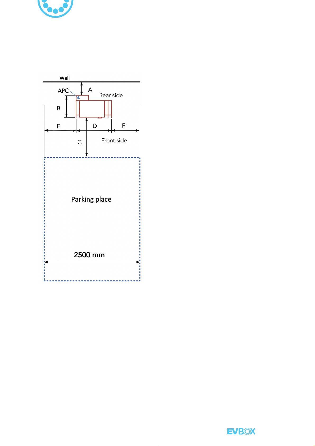
3.2
Charger positioning (with Auxiliary power cabinet – APC).......................................7
3.3
Charger installation on site.......................................................................................8
3.3.1 Installation with Mounting kit (recommended option): ........................................8
3.3.2 Charger foundations WITHOUT Auxiliary power cabinet (APC):..........................9
3.3.3 Preparing and installing the charger WITHOUT Auxiliary power cabinet (APC):11
3.3.4 Charger foundations WITH Auxiliary power cabinet (APC): ...............................14
3.3.5 Preparing and installing the charger WITH Auxiliary power cabinet (APC):.......14
3.3.6 Installation directly with chemical anchor: * .......................................................17
4. ELECTRICAL GRID CONNECTION ................................................................................18
4.1
Electrical connection for charger without storage..................................................18
4.2
Electrical connection for charger with storage .......................................................19
4.3
Passage of the input cables....................................................................................19
4.4
Special attention should be paid to the ground cable...........................................20
4.5
Special attention to the need for a surge arrester..................................................20
5. COMMISSIONING..........................................................................................................21
5.1
Opening procedure locks:
...................................................................................... 21
5.2
Charger restart procedure without battery
............................................................22
6. APPENDIX 1:...................................................................................................................23
Connection grid terminal block..............................................................................................23
7. APPENDIX 2:...................................................................................................................25
Cables passage ......................................................................................................................25
8. APPENDIX 3:...................................................................................................................27
Dimensions.............................................................................................................................27
9. APPENDIX 4:...................................................................................................................29
Connection terminals details: power and communication.....................................................29
10. APPENDIX 5: ..............................................................................................................32
COMMISSIONING VALIDATION REPORT ............................................................................32

Page 3/34
1. SPECIFICATIONS
Equipment without storage option:
50 kW
Grid connection
400 V
AC
+/- 10%
77 A (nominal) / 87 A (maximum)
54 kVA
50 Hz
3P + N + T
Neutral network TT or TN
IT (optional)
Output DC Charge
DC 500 V / 120 A / 50 kW
Output AC Charge
Mode 3: AC 400 V / 63 A / 43 kW
Mode 2: AC 230 V / 10 A / 2,3 kW (optional)
Connectors
DC 1: CHAdeMO
DC 2: CCS2
AC Mode 3: Type 2 tethered cable for 43 kW or Type 2 socket
outlet for 22 kW
AC Mode 2: Type E or F Domestic socket (optional)
Charging cables length
3,95 m with cable auto-retractable system
Weight
345 (Bi-standard) / 350 kg (Tri-standard)
Dimensions WxHxD (mm)
820 x1920 x 465 (Bi-standard) / 920 x1920 x 465 (Tri-standard)
External Housing material
Aluminum and stainless steel
IP level / IK level
IP54 / IK10
Operating temperature
-30°C to +50°C
Storage temperature
-40°C to +70°C
Relative Humidity
5% to 95% without condensation
Altitude
<2000 m
Cooling system
Forced air ventilation
Technology
IGBT, Low Frequency insulation

Page 4/34
Identification
RFID, NFC (card or telephone), SMS, Keyboard
Communication
GPRS or Ethernet / OCPP 1.5; 1.6
Internal electrical security
RCBO 30 mA Type A; RCD 30 mA Type A + 6 mA detection;
MCB curve C/D
Standby power
consumption
100 W
Efficiency at nominal
output power
95%
Certification
CHAdeMO compliant, EV/ZE READY compliant
Standards
CE Compliant, IEC 61851-1,
IEC 61851-21, IEC 61851-22, IEC 62196
(plug)
Equipment with storage option:
36 kW + 15 kW storage option
Grid connection
400 V
AC
+/- 10%
52 A (nominal) / 60 A (maximum)
36 kVA
50 Hz
3P + N + T
Neutral network TT or TN
IT (optional)
Output DC Charge
DC 500 V / 120 A / 50 kW
Output AC Charge
Mode 3: AC 400 V / 60 A / 41 kW
Mode 2: AC 230 V / 10 A / 2,3 kW (optional)
Weight
350 kg + 45 kg - 2 battery modules
350 kg + 55 kg - 3 battery modules
350 kg + 65 kg - 4 battery modules
350 kg + 85 kg - 6 battery modules

Page 5/34
2. TRANSPORT
The following commissioning requirements are given for information and do not commit in anyway,
EVBox responsibility. The charger should be installed by a qualified installer, and be carried out
"according to state of the art" and adapted to the specificities of the installation site and the own
countries rules.
2.1 Load
In case that the charger comes with storage system, its maximum total weight excluding packaging is
estimated to be 450 kg.
2.2 Packaging
The charger will be protected against external hangings with safety conventional material. However,
you must be careful not to use tools that can get through the packaging and damage the charger.
2.3 Logistics
The lower support of the charger is equivalent to the shape of a pallet. A lifting system pallet type is
therefore sufficient to move and install it. However, be careful to remove the charger from the delivery
van; it will eventually be necessary to provide a lifting system with a necessary working height (about
1,3 m).
The transportation and the set up can only be done in an appropriate manner:
-For moving, using of a pallet truck with a charge capacity of at least 1000 Kg.
- For placement, using a pallet truck (> 150 mm of rising) or a forklift truck with a charge capacity of
at least 1000 Kg, and before that it is necessary to check the stability of the charger on the machine.
2.4 Warnings!
To ensure secure installation, make sure to follow these recommendations and thus avoid:
- Transporting the charger in a manner other than upright.
- Carrying the charger in any other ways than those indicated above.
- Using a lifting device while the charger is s electrically connected.
- Using a crane type hoist that would not support the weight of the charger. The use of slings is
allowed by taking the charger through the lower support.
- The charger’s centre of gravity is located in the central position, thus care is needed when
handling.

Page 6/34
3. CIVIL ENGINEERING
3.1 Charger positioning (without Auxiliary power cabinet – APC)
As there are some limitations (including cables length), we recommend the following installation for
the charger in relation to a parking space of 2500 mm width:
A: Distance to the wall
àMinimum: 100 mm to do not compromise
good ventilation
àMinimum: 600 mm to do not compromise
the access to the rear socket type E or F
B: Depth of the charger
à448 mm
C: Distance between charger and parking
place as marked on the ground:
àMinimum: 500 mm to allow free access to
emergency stop and the HMI
àMaximum: 800 mm limited by the length
of the vehicle charging cables
D: Width of the charger
à920 mm
E & F: Distance to the parking place
àMinimum: 550 mm not to hinder the user
when handling the connector.
àMaximum: 930 mm, limited by the length
of the vehicle charging cables.
(A + B + C) minimum = 1048 mm
Warning:
- It is recommended, so as to avoid
overheating, install it under a shelter or
shaded-area in order to protect from direct
sunlight.
- If installed indoors, the room should be
ventilated by a permanent air exchange
system. The ventilation rate of the charger
can reach 1200 m3/h.
Wall
Rear side
Front side
Charger
Parking place
2500 mm

Page 7/34
3.2 Charger positioning (with Auxiliary power cabinet – APC)
As there are some limitations (including cables length), we recommend the following installation for
the charger in relation to a parking space of 2500 mm width:
A: Distance to the wall
àMinimum: 600 mm to do not compromise
the access to the rear socket type E or F as
well as to the Auxiliary power cabinet (APC).
B: Depth of the charger
à648 mm
C: Distance between charger and parking
place as marked on the ground
àMinimum: 500 mm to allow free access to
emergency stop and the HMI
àMaximum: 800 mm limited by the length of
the vehicle charging cables
D: Width of the charger
à920 mm
E & F: Distance to the parking place
àMinimum: 550 mm not to hinder the user
when handling the connector.
àMaximum: 930 mm, limited by the length of
the vehicle charging cables.
(A + B + C) minimum = 1748 mm
Notes:
- It is recommended, so as to avoid
overheating, install it under a shelter or
shaded-area in order to protect from direct
sunlight.
- If installed indoors, the room should be
ventilated by a permanent air exchange
system. The ventilation rate of the charger
can reach 1200 m3/h.
Charger

Page 8/34
3.3 Charger installation on site
The structural engineering is to be performed according to the rules of art, including:
- The concrete used must have a density of 350 kg/m3and should be frost proof.
- The charger shall be secured to the ground and perfectly levelled.
o Indeed, a tilt gap left/right or front/rear can damage the permeability of the product.
o This will require setting the system level without ever using washers or other material that
does not guarantee continuous support between the base of the charger and the ground.
Reminder of the key data of the charger subsets:
- The screen of the charger is located at a height of 125 cm.
- The emergency stop button is located at a height of 104 cm.
- The charging car connectors are located at a height of 118 cm.
- These heights must be considered to avoid compromising the use of HMI from the charger in case
it is raised by a concrete foundation.
Note:
- It is
recommended not to raise the charger more than 18 cm from the ground level where the user
will be positioned.
- For the reasons above, we strongly recommend the use of our mounting kit.
3.3.1 Installation with Mounting kit (recommended option):
To ensure proper installation and therefore durability of our products, we recommend using the
clamping/sealing kit sold as an option with your charger.
The clamping/sealing kit comprises:
- The upper sheet plate, raw aluminium, will remain on the surface (outside) 0,5 cm over the
concrete, acting as a guide for electrical conduit and charger support.
- The lower sheet plate, galvanised, widely perforated for effective penetration into the concrete,
will be sealed in concrete as shown in the sealing insert.
- 10u x M12 nuts.
How to assemble:
1. Screw one M12 nut from the upper end of each threaded rod.
2. Mount the upper plate (alumimium).
3. Screw one M12 nut on each threaded rod above the upper face of the upper plate.
4. The distance between plates must be 4,5 cm.
5. The distance from the upper plate (Al) to the upper end of the threaded rod must be 7,5 cm as a
maximum.

Page 9/34
3.3.2 Charger foundations WITHOUT Auxiliary power cabinet (APC):
The different steps of installation are:
Step 1:
- Dig a hole at selected location of minimum dimensions on the plan (> 720 mm x > 410
mm). The disbursement depth should be greater than 700 mm. Don’t forget to allocate
room for the cables passage indicated in APPENDIX 2.
Step 2:
- Place and lock the clamping/sealing kit with regards to the specified measures as shown in the next
drawing. With no clamping kit available, lock the equipment to ground using chemical sealant.
The clamping kit has a specific mobile metal sheet (upper sheet) to tune the ground level
whenever necessary.
> 720 mm
> 410 mm
Cable input
Deep 700 mm
Rear side
Front side
Front side
2
1
3

Page 10/34
Notes:
1. Leave the upper sheet metal 0,5 cm over the concrete (outside), to leave the bottom nuts
accessible.
2. Before setting the charger the upper sheet metal has to be levelled.
3. The lower sheet metal must be inside the concrete at least 4 cm.
Step 3:
- Set up and install electric cables as stated in annex 2. Please allocate sufficient cable length to
include an excess of minimum 1000 mm over the ground level for proper connection to the
equipment.
* If the charger is to be used independently, it is not necessary to use two electrical conduits.
Step 4:
Ground
Sand
Concrete
Sand
Concrete
Incoming
power line
Power line to
Satellite units
*
ç
*
ç
Front side

Page 11/34
- Place concrete up to the ground level. The lower plate must be sealed at least 4 cm in the concrete.
The five available threaded rods must have a height of 80 mm from the ground.
Step 5:
- Allow it to dry for the time required.
Note:
1. If necessary, level the terminal support plate (raw aluminium) using the bottom nuts.
3.3.3 Preparing and installing the charger WITHOUT Auxiliary power cabinet
(APC):
To be movable and easily installed, some mechanical parts can be removed prior to installation:
Step 1:
- Remove the front bumper by unscrewing the screws from the inside and underside of the door.

Page 12/34
Step 2:
- Remove the rear plate by unscrewing the two nuts shown with red arrows in the picture from
below and from the front of the system.
Step 3:
- Take off the front grommet cover (bezel) by removing the two screws shown in the picture by red
arrows.
Internal overview:
Feeding cables acces

Page 13/34
Step 4:
- Bring the charger near to its final location in accordance with the transport safety notes
"Transportation" (See chapter 2)
Step 5:
- Remove the M12 nuts from the upper metal sheet and Install the charger over the 5 threaded
rods
which come out of the ground, it must pass through the 5 holes of the chassis, green
arrows as shown bellow:
Chassis fastening holes to the ground

Page 14/34
Step 6:
- Rise the charger using a forklift and place it over the 5 threaded rods
which come out of the
ground
. Lower it slowly.
Step 7:
- Tight the M12 nuts provided, the maximum torque has to be between 40 and 50 Nm.
Step 8:
- Route the electrical cables, and then install again the front grommet cover (bezel).
Step 9:
- Assemble again the rear plate and the front bumper.
Notes:
-Never disassemble electrical terminals connected in advance (factory) to facilitate cable feeding.
-
Check charger levelling, it should be perfectly levelled.
3.3.4 Charger foundations WITH Auxiliary power cabinet (APC):
If the charger to be installed is equipped with the auxiliary power cabinet, the steps for making the
base are the same as in the previous point, 3.3.1.1, but the passage of the electrical conduit must be
done behind the charger, as shown below:
3.3.5 Preparing and installing the charger WITH Auxiliary power cabinet (APC):
To be movable and easily installed, some mechanical parts can be removed prior to installation:
>720 mm
>410 mm
230 mm
125 mm
Arrivée
réseau EDF
Béton
Sol
30 mm Mini
tout autour
Incoming
power line
Concrete
Sand

Page 15/34
Step 1:
- Remove the rear input cable cover from back of the charger as shown with two red arrows in the
picture, the rear plate by unscrewing the three nuts from below as shown with orange arrows and
the Meter and Input fuses lids.
Meter
Input
Fuses
Triangle lock
Triangle lock
Rear input
cable cover

Page 16/34
Step 2:
- In order to install the charger over the threaded rods, please follow all the steps as in the
previous point, “3.3.1.2 Preparing and installing the charger WITHOUT Auxiliary power cabinet
(APC)”
Step 3:
- In this case, the electrical connection of the charger has to be done in the rear side, as shown in
the next picture. Insert the cables through the bottom of the fuses box and connect them.
Step 4:
- Replace all the covers.
The connection cable
goes here, in the rear side of the charger

Page 17/34
3.3.6 Installation directly with chemical anchor: *
If the installation already has an adequate concrete floor or there is a problem to make a hole in the
ground (ie. multi-storey car park) the Charger can also be installed by chemical anchor.
1. Make sure to mark every hole of the charger over the floor
2. Drill 5 holes on the floor for M12 threaded rod. Take into account the required drilling depth.
3. Blow into the holes to eliminate the rests of the drill.
4. Inject the adhesive starting at the bottom of the holes.
5. Introduce the M12 threaded rod within the work time.
6. Adjust the distance of the threaded rod and wait for the curation time. A = 8 cm
*This is the advised procedure. Follow in every moment the instruction of your chemical anchor
system.

Page 18/34
4. ELECTRICAL GRID CONNECTION
4.1 Electrical connection for charger without storage
The electrical connection is the responsibility of customer and should be done by qualified person.
The charger should be connected to an electrical grid:
3 Phases plus neutral (3P + N + PE)
400/230 V +/- 10%
50 Hz
Neutral network TT or TN, (IT under option)
Notes:
1. The short-circuit current at the connection point has to be below 10 kA.
2. The loop impedance of the earthing system must be less than 20 ohms.
This connection must be protected upstream by:
- A head switch capable of handling at least 120 A to electrically isolate the charger in case of
maintenance.
- A tetra polar circuit breaker (MCCB), curve D, 120 A, suitable for 54 kVA equipment.
- A Residual current device (RCD) capable of handling at least the maximum current of the above-
mentioned circuit breaker with a sensitivity of 300 mA; type A, HI, S.
- The electrical connection is made internally on terminal X1 (see APPENDIX 1) by feeding through
the power cables using the channel provided for this purpose (see APPENDIX 2).
- It should be ensured that the section of the power supply cable is sufficient. This section is
defined according to the maximum rated current of the charger, the voltage drop and the
installation method.
Note:
1. Size according to the regulations and standards in force in the country of installation.
Thus, to calculate the required minimum section, be aware that a fast charging station has a maximum
primary current of:
- 50 kW model: 87 A per phase with power factor > 0.98

Page 19/34
4.2 Electrical connection for charger with storage
Follow all the instructions shown in the previous point “4.1 Electrical connection for charger without
storage” but taking in account next values:
- A head switch capable of handling at least 80 A to electrically isolate the charger in case of
maintenance.
- A tetra polar circuit breaker (MCCB), curve D, 80 A, suitable for 36 kVA equipment.
- A Residual current device (RCD) capable of handling at least the maximum current of the
above-mentioned circuit breaker with a sensitivity of 300 mA; type A, HI, S.
- 36 kW model: 60 A per phase with power factor > 0.98.
4.3 Passage of the input cables
We recommend the use of a flexible multicore 3P+N+T cable or independents flexible cables for
easy installation (either copper or aluminium). A rigid cable can be used, but at the expense of
comfort of the installer.
Be aware about the specific countries rules, there might be some differences in the conductor
material and the kind of cable coating.
It is advisable to adjust the length of the cables to terminal blocks in order to have the least amount
of cable inside the terminal (while retaining some flexibility).
To access the passage of the input cables and their connection to the terminal (see APPENDIX 1),
please remove various covers (see point 3.3.4) from the charger (no need to remove the rear cover)
taking care to remove the ground wires if necessary (do not forget to put them back when
reassembling).
The entrance of the cables (green circle) is accessible on the front side
Feeding cables

Page 20/34
4.4 Special attention should be paid to the ground cable
The ground impedance must be lower than 20 ohms in dry weather to ensure
proper system operation. An earthing greater than 20 ohms load can cause
unwanted stops.
There should be an equipotential bond between the terminal and ground of the
electricity supplier.
There should also be an equipotential with any metal object located near the
charger.
4.5 Special attention to the need for a surge arrester
The presence of a surge arrester to protect the charger power line is the responsibility of the installer.
Indeed, the presence and selection of the material must be adapted and in compliance with the
regulations and standards in force in the countries where the charger is installed.
Table of contents
Other EVBox Batteries Charger manuals

EVBox
EVBox Elvi User manual

EVBox
EVBox HomeLine User manual

EVBox
EVBox BusinessLine User manual

EVBox
EVBox 9835662780 User manual

EVBox
EVBox Elvi User manual

EVBox
EVBox Iqon Guide

EVBox
EVBox Smart Charging User manual

EVBox
EVBox 9835662680 User manual

EVBox
EVBox Troniq 100 User manual

EVBox
EVBox BusinessLine User manual

EVBox
EVBox BusinessLine series User manual

EVBox
EVBox Wall box Series User manual

EVBox
EVBox Elvi User manual

EVBox
EVBox BusinessLine User manual

EVBox
EVBox 9835662680 User manual

EVBox
EVBox Elvi User manual

EVBox
EVBox BusinessLine User manual

EVBox
EVBox HomeLine User manual

EVBox
EVBox Elvi User manual

EVBox
EVBox Iqon Guide