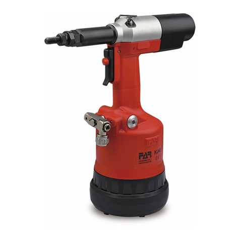
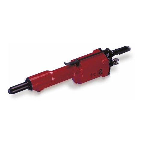
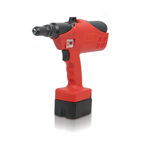
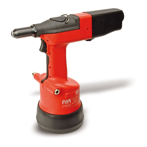
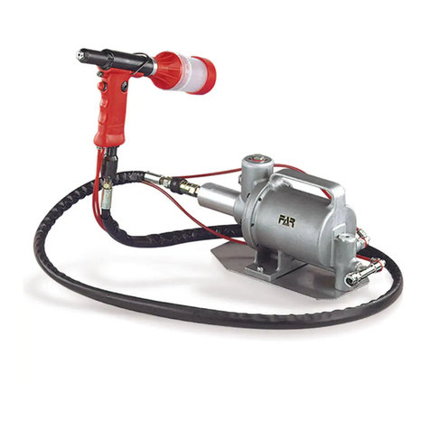
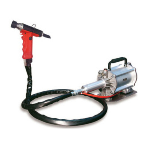
FAR KJ 60 Service manual

I –ПЕРЕВОД С ОРИГИНАЛА
Гидропневматический инструмент
для гаечной заклепки М3-М8
ИНСТРУКЦИЯ ПО ИСПОЛЬЗОВАНИЮ
GB - TRANSLATION OF ORIGINAL INSTRUCTIONS
OIL PNEUMATIC RIVETING TOOL
FOR INSERTS M3/M8
INSTRUCTIONS FOR USE - SPARE PARTS

.............................................
Far S.r.l. - Giacomo Generali
(Председатель Совета Директоров)
(Chairman of the Board of Directors)
IНижеподписавшееся Far S.r.l., сместонахождением
офиса впо адресу Италия, Куарто Инфериоре
(Болонья), ул. Джованни XXIII, д. 2,
ЗАЯВЛЯЕТ
под свою полную ответственность, что
заклепывающее устройство KJ 60 –
гидропневматический инструмент для резьбовых
вставок размером M3÷M8, к которому относится
настоящая декларация соответствует основным
требованиям безопасности предусмотренными
Законодательным декретом 17/2010
транспонирования Директивы по машинам 2006/42/CE
и последующими модификациями и дополнениями.
Уполномоченным лицом для создания технической
документации является господин Джакомо Дженерали
(Giacomo Generali), в головном офисе компании Far
S.r.l., который расположен по адресу: Италия, Куарто
Инфериоре (Болонья), ул. Джованни XXIII, д. 2.
EN
EN
The undersigned Far S.r.l., having its office in Quarto
Inferiore (BO), Via Giovanni XXIII No. 2, herewith
DECLARES
on its sole responsability that the riveting machine Type:
KJ 60 - Hydropneumatic tool
Application: for threaded inserts M3÷M8
which is the object of this declaration complies with the
basic safety requirements estabilished in the law decree
Leg. D. 17/2010 of the Machinery Directive 2006/42/ CE
acknowledge and subsequent amendments and
integrations.
The person who is authorized to create the technical
brochure is Giacomo Generali, c/o Far S.r.l.,
head office in Quarto Inferiore (BO), via Giovanni XXIII n.
2.

RU ИНСТРУКЦИЯ ПО
ИСПОЛЬЗОВАНИЮ ........................3
GB INSTRUCTIONS FOR USE ..................7
RU ЗАПЧАСТИ …………………..........…….…..12
GB SPARE PARTS ………………………………13
PL

ИНСТРУКЦИЯ ПО ИСПОЛЬЗОВАНИЮ
СОДЕРЖАНИЕ
ГАРАНТИЯ И ТЕХНИЧЕСКАЯ ПОМОЩЬ..............9
ТРЕБОВАНИЯ И МЕРЫ БЕЗОПАСНСТИ..............9
МАРКИРОВКА ИНСТРУМЕНТА.......................10
ОБЩИЕ ЗАМЕЧАНИЯ И ИСПОЛЬЗОВАНИЕ.........10
ОСНОВНЫЕ КОМПОНЕНТЫ .........................10
ТЕХНИЧЕСКИЕ ДАННЫЕ.............................10
УСТАНОВКА ВСТАВКИ ...............................11
СМЕНА РАЗМЕРА.....................................12
ЗАЛИВКА МАСЛА В МАСЛЯНУЮ СИСТЕМУ ........13
УТИЛИЗАЦИЯ ИНСТРУМЕНТА.......................13
ГАРАНТИЯ ИТЕХНИЧЕСКАЯ ПОМОЩЬ
Гарантия на заклепочные инструменты FAR составляет 12
месяцев. Гарантийный период начинается со дня доставки
инструмента, что указывается в соответствующем документе.
Гарантия распространяется на инструмент, приобретённый у
официального дилера и только если он используется в целях,
для которых он предназначен. Гарантия не действительна,
если инструмент используется не в соответствии с
инструкцией. При наличии брака или повреждений, FAR S.r.l.
берет на себя обязательства по ремонту или замене деталей,
только если компания признает случаем гарантии.
ТРЕБОВАНИЯ И МЕРЫ БЕЗОПАСНОСТИ
ВНИМАНИЕ!!!
Все операции должны проводиться в
соответствии с требованиями техники
безопасности, чтобы избежать тяжелых
последствий для вашей жизни и обеспечить
лучшую работу инструмента
•Прочтите внимательно инструкцию перед использованием
инструмента.
По вопросам обслуживания и ремонта свяжитесь с
авторизированными центрами FAR s.r.l. и используйте только
оригинальные запасные части. FAR s.r.l. не несет
ответственность за ущерб причинённый бракованными
деталями, вследствие несоблюдения приведенных выше
правил (Директива CEE 85/374).
Список сервис-центров доступен на нашем
веб-сайте http://www.far.bo.it (Organization)
•Инструмент должен использоваться только
квалифицированным персоналом.
•При работе с инструментом необходимо использовать
средства защиты глаз и перчатки.
•Для заливки масла мы предлагаем использовать только те,
жидкости, которые указаны инструкции.
•В случае попадания масла на кожу, промойте это место
водой и мылом.
•Инструмент может переноситься, поэтому после
использования положите его футляр.
•Инструменту требуется тщательный осмотр каждые шесть
месяцев.
•Ремонт и чистка инструмента должны проводиться в
отключенном состоянии.
•Когда возможно предлагается использовать балансир.
•Если уровень шума превышает 70 dB (A), вы должны
использовать средства защиты органов слуха (наушники и
т.д.).
•Рабочее место должно быть всегда чистым иприбранным.
•Не позволяйте неквалифицированному персоналу
использовать рабочий инструмент.
•Удостоверьтесь что у шлангов подачи сжатого воздуха
верный размер.
•Не переносите инструмент за подсоединенный шланг. Шланг
не должен храниться возле нагревательных приборов и
острых предметов.
•Храните инструмент вхороших условиях; не убирайте из
футляра запасные части и глушитель.
•После ремонта и/или регулировки удостоверьтесь, что вы
уже убрали регулировочные инструменты.
•Перед отсоединением воздушного шланга удостоверьтесь,
что в шланге отсутствует давление.
•Тщательно следуйте этим инструкциям.
ВНИМАНИЕ! Перед использованием инструмента,
смонтируйте защитное дно, как изображено на рисунке
внизу.
FAR не несет ответственности за повреждения инструменту,
нанесённые кем-либо в результате отсутствия этой детали.
KJ 60
Revisione - 18 Date 01-20123
МАРКИРОВКА ИНСТРУМЕНТА
Заклепочный инструмент KJ 60 имеет маркировку, на
которой указаны название компании иадрес
производителя, обозначение инструмента, отметка
ЕС и год производства. При запросе обслуживания,
пожалуйста, делайте ссылку на информацию,
указанную на шильдике.
KJ 60
Название компании иОбозначение инструмента
адрес
KJ 60
Год производства
ОБЩИЕ ЗАМЕЧАНИЯ И ИСПОЛЬЗОВАНИЕ
Инструмент может быть использован только для
нарезных вставок срезьбой, диаметр M3 ÷ M8.
Пневматическая система инструмента KJ 60 гарантирует
большую производительность, чем пневматическая,
используемая для других моделей. Это означает уменьшение
проблем из-за износа деталей, тем не менее, увеличение
надежности. Примененные технические решения уменьшают
размеры ивес инструмента, что делает инструмент удобным.
Возможности протечки масла из масляной системы устранены
при помощи уплотнительных прокладок.
ОСНОВНЫЕ КОМПОНЕНТЫ
A)
...............................
Стяжная шпилька с резьбой
B)
...............................
Головка
C)
...............................
Блокирующее кольцо головки
D)
...............................
Кнопка нагрузки
E)
...............................
Кнопка отвинчивания
F)
...............................
Зажимная муфта вставки
G)
...............................
Круглая гайка регулировки удара
H
...............................
Присоединение балансира
I)
...............................
Пневматический мотор
L)
...............................
Пробка масляного бака
M)
...............................
Соединение подачи сжатого воздуха
N)
...............................
Защитное дно
ТЕХНИЧЕСКИЕ ДАННЫЕ
• Рабочее давление
6 бар
• Мин. внутр. диам. шланга подачи сжатого
воздуха
мин. диам = 8 мм.
• Расход воздуха за цикл
9 л.
• Макс. усилие
6бар-13656N
• Вес
2,212 кг.
• Рабочая температура
-5°/+50°C
• Суммарное значение частотно –
взвешенного среднеквадратичного,
ускорения (Ac), которому подвергаются
верхние конечности
< 2.5 m/s2
• Эквивалентный уровень испускаемого
звукового давления (A)
70 dBA
• Эквивалентный уровень мгновенного
значение звукового давления (C)
.<130 dBC
• Эквивалентный уровень звукового
давления (A)
88 dBA
ПОДАЧА ВОЗДУХА
При подаче воздуха не должно быть присутствия инородных
тел ивлажности, чтобы защитить инструмент
преждевременного износа деталей. Тем не менее, мы
советуем использование группы смазочных материалов для
системы сжатого воздуха.
4Date 01-2012 Revisione - 18

УСТАНОВКА ВСТАВКИ
Удостоверьтесь, что пара стяжная шпилька иголовка, установленная на вашем инструменте соответствует
размеру вставки, впротивном случае поменяйте на соответствующий размер. Обычно заклепочный инструмент
поставляется спарой, соответствующей размеру резьбы M8. Перед использованием инструмента ипосле
изменения размера, выполните следующие операции всоответствии размером итолщиной зажимаемого
материала. Настройте силу пробития поворачивая гайку “G” к“–”. Установите вставку на шпильку ислегка
надавите на нее для автоматического зажатия. Удостоверьтесь, что головка вставки касается головки
инструмента должным образом. Закрепите вставку идля надежного зажатия зажимаемого материала,
отрегулируйте силу пробития поворачивая “G”. Увеличивая силу пробития, т.е. поворачивая гайку “G” к“+”,
расстояние “h” между головкой и вставкой будет уменьшаться и зажатие будет более эффективным.
ВНИМАНИЕ!!! НЕПРАВИЛЬНАЯ РЕГУЛИРОВКА ХОДА МОЖЕТ СТАТЬ ПРИЧИНОЙ
ПЛОХОГО ЗАЖИМА ВСТАВОК И ВЕРОЯТНОЙ ПРИЧИНОЙ ПОЛОМКИ СТЯЖНОЙ
ШПИЛЬКИ.
G
–
Revisione - 18 Date 01-2012 5

СМЕНА РАЗМЕРА
В зависимости от резьбы вставки необходимо заменить пару «шпилька-головка» в следующем порядке:
РИС. 1. Ослабьте круглую гайку посредством стандартного 25мм. ключа и снимите головку заклепочного устройства
РИС. 2. Вставьте стержень всоответствующее отверстие обслуживания, расположенного на головке ислегка нажмите на
головку внутрь, чтобы разжать муфту шпильки, в то же время, отвинчивайте шпильку и снимите её.
РИС. 3-4. Удерживайте муфту вразжатом состоянии и завинтите шпильку желаемого размера. Когда замена
произведена, повращайте шпильку, пока не услышите щелчок. Затем установите необходимую головку и закрепите ее
круглой гайкой, ослабленной ранее. Каждый раз, когда вы меняете размер, повторите регулировку как указано на
предыдущих страницах
ВНИМАНИЕ! ПРИ ВЫПОЛНЕНИИ ЭТИХ ОПЕРАЦИЙ ПРЕДВАРИТЕЛЬНО ОТСОЕДИНИТЕ ШЛАНГ ПОДАЧИ
ВОЗДУХА.
1
2
25 mm.
3
4
До
щелчка
25 мм.
6Date 01-2012 Revisione - 18

GB
INSTRUCTIONS FOR USE
INDEX
GUARANTEE AND TECHNICAL ASSISTANCE ........9
SAFETY MEASURES AND REQUIREMENTS ..........9
TOOL IDENTIFICATION ...............................10
GENERAL NOTES AND USE ..........................10
MAIN COMPONENTS..................................10
TECHNICAL DATA.....................................10
PLACING OF THE INSERT ............................11
CHANGE OF SIZE .....................................12
TOOPING UP THE OIL-DYNAMIC CIRCUIT...........13
DISPOSAL OF THE RIVETING TOOL .................13
GUARANTEE AND TECHNICAL ASSISTANCE
FAR riveting tools are covered by a 12-month warranty. The
tool warranty period starts on the date of delivery to the buyer,
as specified in the relevant document. The warranty covers
the user/buyer provided that the tool is purchased through an
authorized dealer and only if it is used for the purposes for
which it was conceived. The warranty shall not be valid if the
tool is not used or maintained as specified in the instruction
and maintenance handbook. In the event of defects or failures,
FAR S.r.l. shall undertake solely to repair and/or replace the
components it judges to be faulty.
SAFETY MEASURES AND REQUIREMENTS
CAUTION!!!
All the operations must be done in conformity
with the safety requirements, in order to avoid
any consequence for your and other people
security and to allow the best tool work way.
•Read the instructions carefully before using the tool.
•For all maintenance and/or repairs please contact FAR s.r.l.
authorized service centers and use only original spare
parts. FAR s.r.l. may not be held liable for damages from
defective parts caused by failure to observe what
mentioned above (EEC directive 85/374).
The list of the service centres is available on
our website http://www.far.bo.it ( Organization )
•The tool must be used only by expert workers.
•A protective visor and gloves must be put on when
using the tool.
•For topping up the oil, we suggest using only fluids in
accordance with the features specified in this working book.
•If any drop of oil touches your skin, you must wash with
water and alkaline soap.
•The tool can be carried and we suggest putting it into its
box after using.
•The tool needs a thorough six-monthly overhaul.
•Repairing and cleaning operations must be done when the tool is
not fed.
•A safety balancer is suggested when it is possible.
•If the A-weighted emission sound pressure level is more than 70
dB (A), you must use some hearing protections (anti-noise
headset, etc.).
•The workbench and the work surface must be always clean and
tidy. The untidy can cause damages to people.
•Do not allow unauthorized persons to use the working tools.
•Make you sure that the compressed air feeding hoses have the
correct size to be used.
•Do not carry the connected tool by pulling the hose. The hole
must be far from any heating sources or from cutting parts.
•Keep the tools in good conditions; do not remove either safety
parts or silencers.
•After repairing and/or adjusting, make sure you have already
removed the adjusting spanners.
•Before disconnecting the compressed air hose from the tool
make sure that there is no pressure in the hose.
•These instructions must be carefully followed.
WARNING! Before using the tool, assemble the
protection bottom supplied with the tool, as
indicated in the picture on side.
FAR has no responsibility for any damages on the tool,
persons or things caused by lack of the protection bottom.
KJ 60
Revisione - 18 Date 01-2012 7

GB
TOOL IDENTIFICATION
The riveting tool KJ 60 is identified from a marking that
shows company name and address of manufacturer,
designation of the tool, CE mark and year of
manufacturing. If any service is requested, please make
reference to the data shown on the marking.
KJ 60
Company name and Designation of the tool
address
KJ 60
Year of manufacturing
GENERAL NOTES AND USE
The tool can be employed only for threaded inserts with thread
of M3 ÷ M8 diameter.
The KJ 60 oil pneumatic system assures more power than the
pneumatic system used for other models. That means a
reduction in the problems due to the wear and tear of the
components, therefore, there will be an increase in reliability.
The technicai solutions adopted reduce the dimensions and
the weight of the tool which, for these reasons, make it very
handy. The possibilities of leakage from the oil-dynamic
system, are eliminated by some sealed gaskets, which solve
this problem.
MAIN COMPONENTS
A) ..................
Threaded tie rod
B) ..................
Head
C) ..................
Ring nut clamping head
D) ..................
Tensile strength pushbutton
E) ..................
Unscrewing pushbutton
F) ..................
Insertion Pin Hole Dechucking clutch
G) ..................
Regulation stroke ring nut
H) ..................
Balancer connection
I) ....................
Pneumatic motor
L) ...................
Oil tank plug
M) ..................
Compressed air connection
N) ..................
Protection bottom
295
80
F
G
H I
Ø 24
Ø 35
A
L
B
288
C
D
E
KJ 60
M
N
Ø109
TECHNICAL DATA
• Working pressure.....................
6 BAR
• Min. int. diam. of the compressed air
feeding hose
min. diam = 8 mm
• Air consumption per cycle........
9 Nl
• Max power.......
6 BAR -13656 N
• Weight.............
2,212 Kg
• Working temperature........
-5°/+50°C
• Root mean square in total acceleration frequency (Ac)
to which the arms are subjected
< 2.5 m/s2
• A-weighted emission sound pressure level .............
70 dBA
• Peak C-weighted instantaneous sound pressure
<130 dBC
• A-weighted emission sound pressure .....................
88 dBA
AIR FEED
The air feed must be free from foreign bodies and humidity in
order to protect the tool from premature wear and tear
of the components in movement, therefore we suggest to
use a lubrificator group for compressed air.
8Date 01-2012 Revisione - 18

GB
PLACING OF THE INSERT
Make sure that the couple tie-rod/head mounted on your riveting tool is suitable for the insert to clamp; otherwise,
change size accordingly. Usually the riveting tool is supplied with the couple tie-rod/head corresponding to a M8 thread.
Before using the riveting tool and after any change of size, perform the following operations according to the size and
thickness of the part to clamp. Adjust the riveting tool stroke to the minimum by turning the ring nut “G” to “–” marked on
the tool. Place the insert on the tie rod and push slightly on it so as to make it clamp automatically. Make sure the insert
head touches the riveting tool head properly. Fasten the insert and in order to ensure a proper clamping of the material,
adjust the riveting tool stroke by turning the ring nut “G” accordingly. By increasing stroke, i.e. by turning the ring nut “G”
to “+”, the distance “h” between head and insert deformation will decrease and clamping will result more effective.
WARNING!!! A WRONG ADJUSTMENT OF THE RIVETING TOOL STROKE
MAY CAUSE A FAULTY CLAMPING OF INSERTS AND MAY BRAKE THE TIE ROD!
G
+
–
Revisione - 18 Date 01-2012 9

GB
CHANGE OF SIZE
Depending on insert thread, it is necessary to replace the couple “tie-rod/head” as follows:
PICTURE 1. Loosen the ring nut by means of a 25-mm standard spanner and remove the riveting tool head.
PICTURE 2. Make the pin supplied pass through the pertinent service hole located on the cone carrying head and apply a light
pressure on the head inwards, in order to dechuck the tie rod clutch., at the same time, unscrew the tie rod and extract it.
PICTURE 3-4. Keep the clutch dechucked and screw the tie rod size desired. When the replacement of the tie rod has been
performed, swing it until you hear a click. Them assembly the proper head and lock it with the corresponding ring nut loosen
before. Each time you carry out any change of size, repeat the adjustment operations as specified in the previous pages.
WARNING! DESCONNECT AIR FEED WHEN PERFORMING THOSE OPERATIONS.
1
2
25 mm.
3
4
Click!
25 mm.
10 Date 01-2012 Revisione - 18

GB
TOPPING UP THE OIL-DYNAMIC CIRCUIT
You need to top up the oil-dynamic circuit after a long period of work, when you note a power loss. Put the riveting tool
(DWELL AND NOT FED) in a horizontal position and remove the plug (A), by means of a 5 mm Allen wrench (equipped
with the riveting tool); during this operation, check the oil level in order to avoid any overflowing. Then, slowly pour the oil
PANOLIN HLP ISO 32 into the bellows container (X) which shall be screwed to its seat on the plug (A). While keeping
the riveting tool in a horizontal position and starting air feeding, push the tensile strength button and make the riveting
tool carry out some cycles until air bubbles inside the container (X) stop coming out. This condition indicates that the
topping up of the oil has fully been achieved. At this point stop the air feeding and, while keeping the riveting tool in a
horizontal position, unscrew and close up the container (X) and the plug (A).
WARNING: it is very important to follow the about mentioned instructions and use gloves. If you need to empty fully the hydraulic
circuit, you must put the oil in a suitable container and contact a Company that is authorized to discharge any waste
WARNING! Before disconnecting the compressed air hose, make sure that it is not under pressure! We
recommend to use oil PANOLIN HLP ISO 32 DIN 51524-2/HLP or similars.
min. 5 Nm
max. 8 Nm
5 mm.
A
X
GB WARNING: Make sure that the oil filler cap
(A) is tightened at a torque corresponding
to Min. 5 Nm ÷ Max. 8 Nm.
DISPOSAL OF THE RIVETING TOOL
Follow the prescriptions of the national laws for disposing of the riveting tool.
After disconnecting the tool from the pneumatic system, disassemble and split all the components
according to the material: steel, aluminium, plastic material, etc.
Then proceed to scrap the materials in accordance with current laws.
Revisione - 18 Date 01-2012 1

ЗАПЧАСТИ
N°
КОД
К-во
ОПИСАНИЕ
КОМ.
N°
КОД
К-во
ОПИСАНИЕ
КОМ.
1
721779
1
Корпус инструмента
75
711728
2
Уплотнительное кольцо 2-016
2
712269
1
Крышка корпуса
76
711730
1
Уплотнительное кольцо 2-119
3
711684
1
Дно цилиндра
77
710367
1
Уплотнительное кольцо 2-008
4
721685
1
Пневматический поршень
78
710376
2
Уплотнительное кольцо 2-009
5
711780
1
Соединение
79
710918
2
Уплотнительное кольцо 2-005
6
721689
1
Гидравлический цилиндр
80
710919
2
Уплотнительное кольцо 2-004
7
711781
1
Стержень
81
710003
2
Уплотнительное кольцо 5-052
8
711691
1
Глушитель
82
710342
2
Уплотнительное кольцо 2-017
9
711692
1
Винт M7 x 1
83
710594
1
Уплотнительное кольцо 2-012
10
711782
1
Демпфер
84
711061
1
Уплотнительное кольцо 5-614
11
711694
1
Нижняя катушка
85
711731
1
Уплотнительное кольцо 2-018
12
711695
1
Резьбовая втулка
86
711732
1
Уплотнительное кольцо 2-118
13
721698
1
Корпус клапана
87
710258
3
Уплотнительное кольцо 5-612
14
711700
1
Верхняя катушка
88
711734
1
Уплотнительное кольцо 2-232
15
711701
1
Корпус верхнего клапана
89
711735
1
Уплотнительное кольцо 2-040
16A
711702
1
Пластина
A
90
711834
2
Глушитель
17
711703
2
Корпус клапана
91
711917
1
Кольцо Parbak 8-119
18
711704
2
Поршень клапана
92B
711933
1
Стопорное кольцо JV 24
B
19
710839
1
Пробка масляного бачка
95
712159
1
Защитное дно
20D
711705
2
Кнопка
D
96
722047
1
Защитный клапан
21B
711713
1
Распорная деталь
B
97
712153
1
Блокировочная пружина шпильки
22
710854
1
Крюк балансира
98
712132
1
Вращающее соединение
23
721387
1
Масляный контейнер
99E
713341
1
Прокладка 1 x 4
E
24
711783

1
Крышка мотора
KIT
25
72A00126
1
Мотор F002
26
711785
1
Защита мотора
N°
КОД
К-во
ОПИСАНИЕ
27
711786
1
Круглая гайка для мотора
KIT A
741702
Комплект пластины
28
711787
1
Стопорное кольцо
16A
711702
2
Пластина
29
712670
1
Муфта
72A
711727
2
Винт TSCE M4 x 8 UNI 5933
KIT B
741713
Комплект распорной детали
30
711790
1
Возвратная пружина поршня
21B
711713
1
Распорная деталь
31
711791
1
Запорная пружина шара
65B
710902
1
Стопорное кольцо ø 16 UNI 7435
32E
711792
1
Втулка шара
E
92B
711933
1
Стопорное кольцо JV 24
33
712270
1
Шток
KIT C
741802
Комплект муфты для шпильки
34
711794
1
Поршень гидравлический
40C
711800
1
Пружина расцепления шпильки
35
711795
1
Переднее соединение
42C
711802
1
Муфта для шпильки
36
711796
1
Вал
60C
710537
1
Стержень пружины ø 4 x 12 UNI 6873
37
711797
1
Фрезерная втулка
KIT D
741705
Комплект кнопки
38
711798
1
Гайка регулирующая пробитие
20D
711705
2
Кнопка
39
711799
1
Кнопка регулирующая пробитие
59D
711726
3
Стержень ø 2 x 20 UNI 1707
40C
711800
1
Пружина расцепления шпильки
C
KIT E
741792
Комплект втулки шара
41
711801
1
Головка несущая шпильку
32E
711792
1
Втулка шара
42C
711802
1
Муфта для шпильки
C
63E
711816
3
Шар ø 2,5
43
711803
1
Круглая гайка головки
99E
713341
1
Прокладка 1 x 4
44
711804
1
Круглая гайка
KIT F
74000043
1
Комплект контейнера стяжной шпильки
45
711805
1
Головка M3
F002
46
711806
1
Головка M4
47
711807
1
Головка M5
1
71345169
1
Соединитель
48
711808
1
Головка M6
2
71C00764
1
Подшипник 61801
49
711809
1
Головка M8
3
71345646
1
Коробка передач
50
711810
1
Шпилька M3
4
71345644
3
Сателитная шестерня
51
711811
1
Шпилька M4
5
71345643
1
Корончатая шестерня
52
711812
1
Шпилька M5
6
71345642
1
Шайба
53
711813
1
Шпилька M6
7
71C00763
1
Подшипник AY7 ZZ C2
54
711814
1
Шпилька M8
8
71345640
1
Соединение
55
710876
1
Стержень расцепления шпильки
9
71C00761
2
Стержень пружины ø 1,5 x 10 UNI 6875
56
710906
1
Герметичная шайба 400-020-4490
10
71345639
5
Шип
59D
711726
3
Стержень ø 2 x 20 UNI 1707
D
11
71345638
1
Ротор
60C
710537
1
Стержень пружины ø 4 x 12 UNI 6873
C
12
71345637
1
Внешний корпус
61
711815
2
Шар ø 3,5
13
71345641
1
Задняя крышка
62
710911
4
Шар ø 4
14
71C00794
1
Стержень ø 2 x 9,8
63E
711816
3
Шар ø 2,5
E
15
71C00762
1
Подшипник 695-ZZ
64
711817
1
Стопорное кольцоø 18 UNI 7437
16
710376
2
Прокладка OR 2-009
65B
710902
1
Стопорное кольцоø 16 UNI 7435
B
17
71C00529
1
Прокладка XR 008 PP180 B
66
711818
1
Стопорное кольцоSW 11
18
720025
1
Направляющий стержень мотора
67
711821
1
Стопорное кольцоJV 20
19
711869
1
Пружина
68
711721
1
Прокладка B 110078/1/B/NEO
20
711865
1
Винт M10
69
711722
1
Прокладка B 094063/B/NEI
A
72A00126
1
Мотор в сборе
70
711819
1
Прокладка B 070039/1
KIT
71
711820
1
Прокладка TS 10-18-5,8/L
72A
711727
1
Винт TSCE M4 x 8 UNI 5933
A
Ком. A
74000051
Комплект крышки корпуса
KIT
Означает, что деталь продается в комплктах, состоящих из
различных деталей в разных количествах.
73
712037
2
Фильтр из нерж. ст. ø 6 x 4
74
711092
1
Ключ 5мм.

SPARE PARTS
No.
CODE
Q.ty
DESCRIPTION
KIT
No.
CODE
Q.ty
DESCRIPTION
KIT
1
721779
1
Tool body
75
711728
2
Gasket OR 2-016
2
712269
1
Body cover
76
711730
1
Gasket OR 2-119
3
711684
1
Cylinder bottom
77
710367
1
Gasket OR 2-008
4
721685
1
Pneumatic piston
78
710376
2
Gasket OR 2-009
5
711780
1
Connector
79
710918
2
Gasket OR 2-005
6
721689
1
Oleodynamic cylinder
80
710919
2
Gasket OR 2-004
7
711781
1
Steam
81
710003
2
Gasket OR 5-052
8
711691
1
Silencer
82
710342
2
Gasket OR 2-017
9
711692
1
Screw M7 x 1
83
710594
1
Gasket OR 2-012
10
711782
1
Dampener
84
711061
1
Gasket OR 5-614
11
711694
1
Lower coil
85
711731
1
Gasket OR 2-018
12
711695
1
Threaded sleeve
86
711732
1
Gasket OR 2-118
13
721698
1
Valve body
87
710258
3
Gasket OR 5-612
14
711700
1
Upper coil
88
711734
1
Gasket OR 2-232
15
711701
1
Upper valve body
89
711735
1
Gasket OR 2-040
16A
711702
1
Plate
A
90
711834
2
Silencer
17
711703
2
Valve body
91
711917
1
Ring Parbak 8-119
18
711704
2
Valve piston
92B
711933
1
Seeger ring JV 24
B
19
710839
1
Oil tank plug
95
712159
1
Protection bottom
20D
711705
2
Push-button
D
96
722047
1
Safety valve assembly
21B
711713
1
Spacer
B
97
712153
1
Rod locking spring
22
710854
1
Balancer hook
98
712132
1
Rotating connector
23
721387
1
Oil container
99E
713341
1
Gasket 1 x 4
E
24
711783
1
Motor cover
KIT
25
72A00126
1
Motor F002
26
711785
1
Motor protection sector
No.
CODE
Q.ty
DESCRIPTION
27
711786
1
Ring nut for motor
KIT A
741702
Plate Kit
28
711787
1
Stop ring
16A
711702
2
Plate
29
712670
1
Clutch
72A
711727
2
Screw TSCE M4 x 8 UNI 5933
KIT B
741713
Spacer kit
30
711790
1
Piston return spring
21B
711713
1
Spacer
31
711791
1
Ball locking spring
65B
710902
1
Seeger ring ø 16 UNI 7435
32E
711792
1
Ball bushing
E
92B
711933
1
Seeger ring JV 24
33
712270
1
Rod
KIT C
741802
Clutch for tie rod kit
34
711794
1
Oleodynamic Piston
40C
711800
1
Spring disengagement tie rod
35
711795
1
Front connector
42C
711802
1
Clutch for tie rod
36
711796
1
Shaft
60C
710537
1
Spring pin ø 4 x 12 UNI 6873
37
711797
1
Milled sleeve
KIT D
741705
Push-button Kit
38
711798
1
Stroke adjusting nut
20D
711705
2
Push-button
39
711799
1
Stroke adjusting knob
59D
711726
3
Pin ø 2 x 20 UNI 1707
40C
711800
1
Spring disengagement tie rod
C
KIT E
741792
Ball bushing Kit
41
711801
1
Head carrying tie rod
32E
711792
1
Ball bushing
42C
711802
1
Clutch for tie rod
C
63E
711816
3
Ball ø 2,5
43
711803
1
Head ring nut
99E
713341
1
Gasket 1 x 4
44
711804
1
Ring nut
KIT F
74000043
1
Tie rod container kit
45
711805
1
Head M3
F002
46
711806
1
Head M4
47
711807
1
Head M5
1
71345169
1
Connector
48
711808
1
Head M6
2
71C00764
1
Bearing 61801
49
711809
1
Head M8
3
71345646
1
Gear cage
50
711810
1
Tie rod M3
4
71345644
3
Planetary gear
51
711811
1
Tie rod M4
5
71345643
1
Crown gear
52
711812
1
Tie rod M5
6
71345642
1
Washer
53
711813
1
Tie rod M6
7
71C00763
1
Bearing AY7 ZZ C2
54
711814
1
Tie rod M8
8
71345640
1
Connector
55
710876
1
Pin disengagement tie rod
9
71C00761
2
Spring pin ø 1,5 x 10 UNI 6875
56
710906
1
Hermetic washer 400-020-4490
10
71345639
5
Tongue
59D
711726
3
Pin ø 2 x 20 UNI 1707
D
11
71345638
1
Rotor
60C
710537
1
Spring pin ø 4 x 12 UNI 6873
C
12
71345637
1
Outside body
61
711815
2
Ball ø 3,5
13
71345641
1
Back cap
62
710911
4
Ball ø 4
14
71C00794
1
Pin ø 2 x 9,8
63E
711816
3
Ball ø 2,5
E
15
71C00762
1
Bearing 695-ZZ
64
711817
1
Seeger ring ø 18 UNI 7437
16
710376
2
Gasket OR 2-009
65B
710902
1
Seeger ring ø 16 UNI 7435
B
17
71C00529
1
Gasket XR 008 PP180 B
66
711818
1
Seeger ring SW 11
18
720025
1
Motor driving rod
67
711821
1
Seeger ring JV 20
19
711869
1
Spring
68
711721
1
Gasket B 110078/1/B/NEO
20
711865
1
Screw M10
69
711722
1
Gasket B 094063/B/NEI
A
72A00126
1
Complete motor
70
711819
1
Gasket B 070039/1
KIT
71
711820
1
Gasket TS 10-18-5,8/L
72A
711727
1
Screw TSCE M4 x 8 UNI 5933
A
KIT A
74000051
Body cover kit
KIT
It indicates that the part is sold in kits consisting of
different
parts in different quantities.
73
712037
2
Inox filter ø 6 x 4
74
711092
1
Key mm 5
Revisione - 18
Date 01-2012
13

ЗАПЧАСТИ • SPARE PARTS
60 C
41
40 C 67
39
37
82
49
43
54
42 C
48
53
47
52
92 B
21 B
34
36
97
46
51
65 B
68
75
69
66
35
91
76
38
44
45
50
25
90
24
27
28
29
33
6
32 E
31
30
99 E
63 E
85
62
26
62
22
61
61
73
79
64
80
17
18
70
74
78
16 A
56
59 D
81
71
19
86
55
5
23
1
72 A
83
20 D
98
10
7
16A(x2)
KIT D
77
84
4
59D(x3)
15
72A(x2)
9
20D(x2)
75
KIT A
88
87
89
92B(x1)
21B(x1)
KIT E
3
65B(x1)
14
96
32E(x1)
82
8
63E(x3)
13
KIT B
99E(x1)
12
2
42C(x1)
KIT F
11
60C(x1)
40C(x1)
KIT C
95
14
Date 01-2012
Revisione - 18

ЗАПЧАСТИ • SPARE PARTS
F002
7
6
5
4
3
15
2
14
13
9
1
12
11
20
10
19
9
8
18
17
16
KIT A
Revisione –18
Date 01-2012
15

.....................................................................................................................................................................................................
.....................................................................................................................................................................................................
.....................................................................................................................................................................................................
.....................................................................................................................................................................................................
.....................................................................................................................................................................................................
.....................................................................................................................................................................................................
.....................................................................................................................................................................................................
.....................................................................................................................................................................................................
.....................................................................................................................................................................................................
.....................................................................................................................................................................................................
.....................................................................................................................................................................................................
.....................................................................................................................................................................................................
.....................................................................................................................................................................................................
.....................................................................................................................................................................................................
.....................................................................................................................................................................................................
.....................................................................................................................................................................................................
.....................................................................................................................................................................................................
.....................................................................................................................................................................................................
.....................................................................................................................................................................................................
.....................................................................................................................................................................................................
.....................................................................................................................................................................................................
.....................................................................................................................................................................................................
.....................................................................................................................................................................................................
.....................................................................................................................................................................................................
.....................................................................................................................................................................................................
.....................................................................................................................................................................................................
.....................................................................................................................................................................................................


RU Список сервисных центров доступен на нашем веб-сайте
http://www.far.bo.it
GB
The list of the service centres is available on our website
http://www.far.bo.it ( Organization )
FASTENING SYSTEMS • СИСТЕМЫ КРЕПЕЖА
ОФИСНЫЙ ЦЕНТР
• HEAD OFFICE
СКЛАД • WAREHOUSE
40057 Quarto Inferiore - Bologna - Italy
20099 Sesto San Giovanni
Via Giovanni XXIII, 2
Milano
Tel. +39 - 051 6009511
Italy
Ufficio Vendite Fax +39 - 051 767443
Via Archimede, 8
E-mail: [email protected]
Tel. +39 - 02 2409634
www.far.bo.it
Other manuals for KJ 60
4
Table of contents
Languages:
Other FAR Rivet Tools manuals
Popular Rivet Tools manuals by other brands

Würth
Würth HNG 26 N Translation of the original operating instructions

Bosch
Bosch GRG18V-3600C Operating/safety instructions

Gage Bilt
Gage Bilt GB510BOM Original instructions

Schneider Airsystems
Schneider Airsystems NZ - SYS D322311 Original operating manual

Titgemeyer
Titgemeyer RL20-2 operating manual

Sealey
Sealey SA317 instructions